Abstract
The National Transportation Safety Board is an independent federal agency investigating transportation accidents across aircraft, rail, pipeline, marine, highway, and hazardous materials platforms. The agency has investigated multiple accidents involving fractures of landing gear components during touchdown, where the trunnion pins fractured from fatigue. Detailed analysis revealed that the crack initiation sites coincided with areas displaying marks consistent with excessive heating. These marks, or ‘burns’, developed during grinding operations from rework of the parts. The investigation details how fatigue cracks initiate from excessive grinding, the fracture morphologies observed, and the diagnosis of the issue in an investigation. Safety improvements were developed to prevent the fracture from recurring, noting the challenges of finding areas of excessive grinding on high-strength steel parts during rehabilitation.
1. Introduction
The National Transportation Safety Board (NTSB) investigated two recent major aviation accidents involving passenger-carrying commercial Boeing 737–800 aircraft operating under Part 121, both of which experienced main landing gear collapses upon touchdown. As detailed in Table 1, these occurred in
- Denver, CO, (N87513) 22 December 2019, (NTSB # DCA20LA047);
- Santa Ana, CA, (N516AS), 20 August 2023, (NTSB # DCA23FA417).

Table 1.
Flight cycle and fatigue crack dimensions for the fractured trunnion pins.
Table 1.
Flight cycle and fatigue crack dimensions for the fractured trunnion pins.
| Airplane | Location | Trunnion Pin Flight Cycles | Cycles Since Rework | Cycles Since Prior Rework | Fatigue Crack Width (mm) | Fatigue Crack Length (mm) |
|---|---|---|---|---|---|---|
| United 2429 | Denver, CO | 23,535 | 2309 | 12,922 | 3.91 | 6.99 |
| Alaska 1288 | Santa Ana, CA | 11,116 | 4710 | N/A | 3.66 | 9.93 |
The trunnion pins from the left main landing gear fractured in both accidents. The trunnion system supports the landing gear when the airplane is on the ground. For commercial airplanes, the pin is made from quench-and-tempered medium-carbon alloy steel as it can withstand high stresses, and it is easy to machine [1]. The pin is coated with chromium, cadmium, and/or nickel for corrosion and wear resistance [2]. Further, the mechanical properties of the alloys used, 4340M and 300M, are sensitive to heat input, so high temperatures can change their microstructure and mechanical properties [3].
Aerospace components have become increasingly expensive, with many used beyond their designed lifetime [4,5]. Trunnion pins are inspected, overhauled, and reinstalled at substantial cost savings versus purchasing new parts [6]. This is based on damage tolerance (inspecting for cracks), rather than safe-life (crack-free) design [7,8]. During overhaul, the corrosion-resistant coatings are mechanically or chemically removed, inspected for cracks and other defects, then recoated and machined to the correct dimensions [9,10].
One of the challenges of grinding quench-and-tempered steels is overheating. Grinding can create untempered martensite if exceeding 727 °C, or overtemper the microstructure if below [11]. As these microstructural changes are localized to the areas of heat input, the microstructural mismatch creates residual stresses on the surface, which, if left unchecked, can lead to fatigue crack initiation and eventual fracture of the parts [12].
Nondestructive testing (NDT) techniques can identify if an alloy steel part has been overheated, and a surface temper etch will show damaged areas from visual contrast by etching rate differences [13]. However, this inspection technique will only work on bare steel surfaces, not those coated with Cr or Cd. Fluorescent penetrant inspection (FPI) can detect any cracks open to the surface in these cases, while magnetic particle inspection (MPI) can detect surface and some subsurface cracks [14]. If calibrated, Barkhausen noise inspection can detect the hardness state of steel using magnetoelastic interaction [15]. Soft materials increase the noise signal amplitude, and hard materials decrease the signal [16].
The NTSB Materials Laboratory’s involvement in these accident investigations revealed the fracture sequence that determined the probable cause of the accident. The investigations also found the approximate time the crack grew, establishing conditions during initiation. Each investigation’s goal is to prevent these issues from recurring.
2. Methods and Materials
The fractured pins that were examined at Boeing Equipment Quality Analysis (EQA) (Seattle, WA, USA) and NTSB Materials Laboratory (Washington, DC, USA). These pins were made of 4340M alloy steel, plated with a Cr electroplating layer, and ground to stated dimensions.
The trunnion pins were photographed with a Canon EOS T5i camera. NDT was performed using the FPI, MPI, and Barkhausen noise inspection (BNI). BNI was calibrated to a heat-damaged steel standard. Later, temper etch inspection using a 2% Nital solution bath was performed after removing the coating with a solution of NaOH and Na2CO3.
Sectioned specimens from the pins were examined using a Keyence VHX-1000 digital microscope. A Zeiss Auriga and ThermoFisher Apreo S field emission scanning electron microscopes (SEM) with energy dispersive X-ray spectroscopy (EDS) were used for fractography. The fatigue crack growth rate on each pin was determined by counting striations at intervals along the crack depth at 30 random, unique, and non-duplicated places using distances from the initiation site. The distances were measured via a calibrated stage on a field emission SEM, with no measurements taken from the overstress regions.
Metallographic cross-sections were mounted, polished to 0.05 μm grit, and etched using a 2% Nital solution. These specimens were inspected using a Zeiss Axio Observer Z1m inverted microscope. The hardness was inspected per ASTM E18 using a Wilson RB2000-T hardness tester. Selected polished and etched cross-sections were examined using a LECO AMH55 automated microindentation hardness tester, per ASTM E384.
3. Results
Figure 1 shows one of the fractured pins, after sectioning. Each fracture surface exhibited a rough, fibrous texture with a dull luster, displaying chevron marks consistent with fracture from small thumbnail-shaped cracks. The dimensions of the thumbnail cracks are listed in Table 1. These features were consistent with an overstress fracture emanating from the pre-existing cracks during landing.
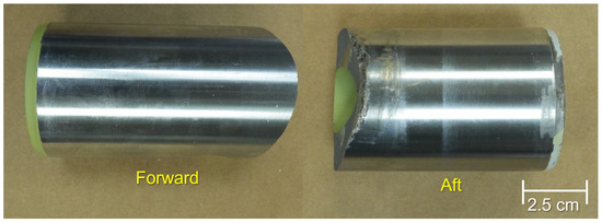
Figure 1.
Remnants of the Denver, CO, trunnion pin, shown in their relative positions.
FPI and MPI examinations found cracking consistent with the remnant impacting the runway after fracture. These areas corresponded to the highest BNI data. However, there were also elevated BNI readings near the fatigue thumbnail cracks on the exterior pin remnant surfaces, extending 2.5 cm longitudinally. These readings were mapped and contrasted with later temper etch results.
As both fatigue cracks exhibited analogous features, the following will detail the fracture features from the Denver, CO pin for brevity. As shown in Figure 2a, the crack exhibited visible crack arrest marks, with two regions of different hues (Figure 2b). In contrast, the Santa Ana, CA, fatigue crack only exhibited a single darker hue. SEM examination revealed dimpled rupture in these areas, dissimilar from the outer adherent chromium electroplated layer, which was 0.13–0.15 mm thick with faceted features (Figure 3a).
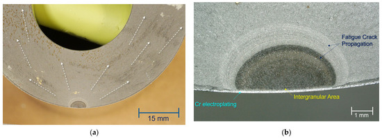
Figure 2.
The (a) forward pin fracture surface from the Denver accident (fracture direction shown by arrows), showing (b) the thumbnail crack and the areas of different fracture features.
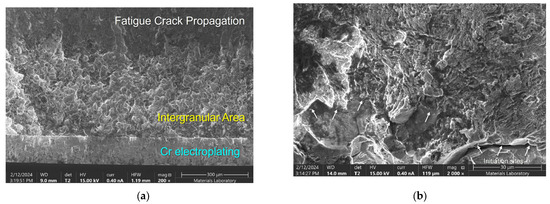
Figure 3.
Secondary electron (SE) micrograph of the (a) origin of the fatigue crack, with the intergranular layer below the external Cr layer, and the (b) initiation sites from several intergranular facets, annotated by the white arrows.
Inward of the coating was an intergranular region approximately 0.28 mm deep and was 1.88 mm wide (Figure 3a). Figure 3b shows several of the intergranular facets, which served as initiation sites for the fatigue crack, indicated by striations propagating upward and annotated with white arrows. Ratchet marks separated these individual initial fatigue cracks. The remainder of the thumbnail crack exhibited striations, consistent with fatigue crack propagation (upper half of Figure 3b). There was no indication of mixed-mode features, such as dimpled rupture or intergranular cracking within the fatigue regions of the darker portions of the thumbnail crack, though some bands of dimpled rupture were observed among fatigue striations in the non-discolored outer bands.
The fracture surfaces were examined using EDS, and the data were consistent with the prescribed 4340M alloy steel composition. EDS examination of the darker crack areas showed elevated O, C, Ca, and Al levels, frequently found on oxidized fracture surfaces.
A wedge section was removed from the forward fracture surface, while the rest of the forward trunnion pin remnant was chemically stripped and then temper etched. Figure 4 shows two areas of darker contrast on the etched pin surface. One area was 12 mm from the fracture, while the other slanted, darker area traversed the fracture origin. These marks were consistent with heat exposure, typical of a previous grinding operation. MPI found parallel ladder cracks in these darker etched regions on the bare pin surface—these cracks were not identified prior to removing the electroplated coating.
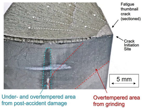
Figure 4.
Three-dimensional constructed optical micrograph of the temper etched cross-section of the fatigue crack, showing the adjacent area of overtempered damage on the surface.
The wedge section opposite the area in Figure 4 was mounted, polished, and etched. Overall, the core microstructure of the wedge cross-section was consistent with tempered martensite. The area beneath the electroplating layer exhibited a darker color response to the Nital etch. The hardness of this darker area measured 52 HRC (540 HV100), whereas the core regions exhibited a hardness between 55 and 56 HRC (592–615 HV100). This darker region was consistent with higher iron carbide content, indicative of localized overtempering, which can reduce hardness locally.
The number of striations found is detailed in Table 1. For the Denver, CO, crack, the cycles from the intergranular initiation site to the end of the crack were 6225, meaning that the cycles in the discolored region were 4150, and were 2075 in the non-discolored region. The number of landings since the last overhaul was 2309 cycles, similar to the number of cycles in the non-discolored portion of the fatigue crack. Assuming the number counted in the non-discolored region was from the number of landings since the last overhaul, the crack had been present for at least 4150 cycles before the last overhaul performed by the airline. For comparison, the previous overhaul performed at a third-party occurred 12,922 cycles before the accident, with 10,613 landings between the two overhauls. Therefore, the crack was present at the last overhaul, but was created at the previous overhaul. The color change on the crack in Figure 2b was consistent with baking at the last overhaul (2039 flights).
For the Santa Ana, CA, crack, the total number of cycles from the intergranular initiation site to the end of the crack was 797. The number of landings since the last overhaul was 4710 cycles. The number of cycles was an order of magnitude lower than the number of landings since the overhaul. These data indicate that a detectable fatigue crack had not been present prior to the part overhaul, though the conditions to create it occurred at the post-plating grinding operation. The data showed that the striation spacing steadily increased over time, typical of increasing crack growth rate during propagation.
4. Discussion and Analysis
The landing gear failed from fatigue cracks in trunnion pins. At each landing, the cracks were large enough to cause overstress fracture of the pins, resulting in landing gear collapse [17].
The cracks initiated from features in the intergranular regions under the external chromium electroplated layer. This intergranular region was consistent with those previously observed in mid-C steels after excessive heat changed the local microstructure; the mismatch between the overtempered region and the surrounding area created residual tensile stresses that can cause intergranular fracture [18,19,20,21]. This process can occur during the baking and stress relief processes during overhaul, or later in service. Multiple fatigue cracks initiated at the facets of this intergranular region. These individual cracks coalesced and propagated inward, indicated by ratchet marks and fatigue striations [22,23,24].
The intergranular region was located along a surface area with a darker visual contrast, as viewed following Nital etching of the surface and cross-section. These regions also showed elevated Barkhausen noise readings, and in the case of the Denver pin, surface cracks after plating removal. These data were consistent with an area of overtempering from high temperature exposure. This darker region exhibited lower hardness, consistent with excessive heat input from grinding performed during overhaul [24].
Fatigue analysis assumed that the airplane’s landing cycle loads generated the largest stress amplitude, and the overall landing sequence was assumed to advance the crack one prominent striation [25]. A review of the routing information found the flight cycles calculated were consistent with the Santa Ana pin crack initiating after the last overhaul event. The fatigue crack in the Denver pin was present at the last overhaul, initiating after a prior overhaul. These investigations found that MPI, used after the Cr electroplating and final machining, was not effective at detecting cracks under the coating. For the Denver case, the coating was not stripped at the last overhaul, since mechanical removal could itself create excessive grinding. The procedure had assumed that a crack capable of propagating to a critical size between inspections would be found by MPI.
These investigations demonstrated that BNI could be valuable in identifying locations subjected to such heat damage. However, this technique is not yet standardized by a society such as the American Society for Nondestructive Testing (ASNT), and it requires skilled operators and excellent calibration standards. As such, this technique has yet to be widely adopted in rework facilities. Eddy current inspection may also be capable of finding these cracks, but the properly trained operators are rarely staffed by overhaul facilities and must be contracted when available and needed.
Mitigating human factors issues is a comprehensive prevention strategy. Machinists should be trained on the effects of excessive grinding and how damage can go undetected following the final plating of overhauled pins. Where grinding and machining tools may be applied too hard, fast, or long, machinists should be encouraged to, and rewarded for, reporting incidents, and suspect parts should be flagged [26]. As even relatively mild heat input can initiate cracks, inspections must be performed on all suspect parts [24].
The industry should advocate awareness of these issues: operators must carefully monitor actions that can be deleterious during grinding. Operators, supervisors, and engineers must be cognizant of proper coolant design, flow, grinding materials, intensities, and dwell times [27]. Operators should be rewarded for reporting discrepancies during rework, particularly those that can impart heat into heat-treated steel parts [28]. These variables can be critical to the long-term safety of refurbished aerospace components.
5. Conclusions and Recommendations
The NTSB Materials Laboratory performed accident investigations on trunnion pins that fractured during landing. Although no fatalities occurred, the landing gear collapses caused significant damage to each aircraft. These pins fractured from fatigue cracks that initiated from grinding burns on the surface created by machining following plating of the exterior Cr layer. MPI used after plating was inconsistent and unable to detect subsurface pin cracks when the plating layer was too thick. As alloy steels are susceptible to crack initiation due to grinding burns, careful attention must be emphasized and encouraged. Maintaining high workplace standards, fostering open communication when potential issues arise, and collaborating are effective strategies to prevent future incidents.
Author Contributions
E.M.M. wrote the manuscript and led the metallurgical group of the investigation. M.M. provided engineering support during the fact-finding stage of the DCA20LA047 investigation. P.C. was the lead investigator for the maintenance groups, providing resources, background, and interviews with personnel in both investigations, as well as reviewing and editing. M.H. was the lead investigator of the DCA23FA417 investigation, providing resources, support, and supervision of the investigation and resulting reports. All authors have read and agreed to the published version of the manuscript.
Funding
This research received no external funding.
Institutional Review Board Statement
Not applicable.
Informed Consent Statement
Not applicable.
Data Availability Statement
The original data presented in the study are openly available at https://www.ntsb.gov/.
Acknowledgments
In accordance with 5 CFR §2635.807(b)(2), the views in this article are those of the authors and do not represent the views of the NTSB or USA. The authors would like to thank the people at Boeing EQA and Sunvair Inc. for their assistance in these investigations.
Conflicts of Interest
The authors declare no conflicts of interest.
References
- Roy, S.; Kumar, R.; Das, R.K.; Sahoo, A.K. A comprehensive review on machinability aspects in hard turning of AISI 4340 steel. IOP Conf. Ser. Mater. Sci. Eng. 2018, 390, 012009. [Google Scholar] [CrossRef]
- Mooney, T. Electroplated Coatings. In Corrosion: Fundamentals, Testing, and Protection, Vol 13A, ASM Handbook; Cramer, S.D., Covino, B.S., Eds.; ASM International: Materials Park, OH, USA, 2003; pp. 772–785. [Google Scholar]
- Ahn, S.H.; Heo, J.; Kim, J.; Hwang, H.; Cho, I.S. The effect of baking heat treatment on the fatigue strength and life of shot peened 4340M landing gear steel. Materials 2020, 13, 5711. [Google Scholar] [CrossRef] [PubMed]
- Phillips, P.; Diston, D.; Starr, A.; Payne, J.; Pandya, S. A review on the optimisation of aircraft maintenance with application to landing gears. In Proceedings of the WCEAM 2009, Athens, Greece, 28–30 September 2009. [Google Scholar]
- Phillips, P.; Diston, D.; Starr, A. Perspectives on the commercial development of landing gear health monitoring systems. Transp. Res. Part C Emerg. Technol. 2011, 19, 1339–1352. [Google Scholar] [CrossRef]
- Greenwood, J.D. The Salvage of Aircraft Undercarriages: A description of the methods used to refurbish landing gear components. Aircr. Eng. Aerosp. Technol. 1968, 40, 32–34. [Google Scholar] [CrossRef]
- Ulus, Ö.; Davarcı, F.E. NDT Methods Commonly Used in Aviation. Int. J. Aeronaut. Astronaut. 2024, 5, 10–22. [Google Scholar] [CrossRef]
- Kaplan, M.P.; Willis, T.; Wolff, T.A. Damage Tolerance Assessment of CASA Landing Gear. SAE Trans. 1997, 972626. [Google Scholar] [CrossRef]
- Voorwald, H.J.C.; Rocha, P.C.F.; Cioffi, M.O.H.; Costa, M.Y.P. Residual stress influence on fatigue lifetimes of electroplated AISI 4340 high strength steel. Fatigue Fract. Eng. Mater. Struct. 2007, 30, 1084–1097. [Google Scholar] [CrossRef]
- Bag, R.; Panda, A.; Sahoo, A.K.; Kumar, R. A perspective review on surface integrity and its machining behavior of AISI 4340 hardened alloy steel. Mater. Today Proc. 2019, 18, 3532–3538. [Google Scholar] [CrossRef]
- Wang, X.Q.; Tao, Z.; Hassan, M.K. Post-fire behaviour of high-strength quenched and tempered steel under various heating conditions. J. Constr. Steel Res. 2020, 164, 105785. [Google Scholar] [CrossRef]
- Blake, G.; Margetts, M.; Silverthorne, W. Gear failure analysis involving grinding burn. Gear Technol. 2009, 62–66. [Google Scholar]
- Seidel, M.W.; Zösch, A.; Härtel, K. Grinding burn inspection. Forsch Ingenieurwes 2018, 82, 253–259. [Google Scholar] [CrossRef]
- Eisenmann, D. Magnetic-Particle Inspection. In Nondestructive Evaluation of Materials, Vol 17, ASM Handbook; Ahmad, A., Ed.; ASM International: Materials Park, OH, USA, 2018; pp. 96–123. [Google Scholar]
- Karpuschewski, B.; Bleicher, O.; Beutner, M. Surface integrity inspection on gears using Barkhausen noise analysis. Procedia Eng. 2011, 19, 162–171. [Google Scholar] [CrossRef]
- Thomas, J. Magnetic Barkhausen Noise for Nondestructive Inspection of Gears. In Nondestructive Evaluation of Materials, Vol 17, ASM Handbook; Ahmad, A., Bond, L.J., Eds.; ASM International: Materials Park, OH, USA, 2018; pp. 590–593. [Google Scholar]
- Shi, D.A.; Liu, Q.; Brandt, M.; Janardhana, M.; Clark, G. Microstructure and mechanical properties of laser cladding repair of AISI 4340 steel. In Proceedings of the 28th International Congress of the Aeronautical Sciences, ICAS, Brisbane, Australia, 23–28 September 2012; pp. 1–9. [Google Scholar]
- Eliaz, N.; Shachar, A.; Tal, B.; Eliezer, D. Characteristics of hydrogen embrittlement, stress corrosion cracking and tempered martensite embrittlement in high-strength steels. Eng. Fail. Anal. 2002, 9, 167–184. [Google Scholar] [CrossRef]
- Islam, M.A.; Bowen, B.; Knott, J.F. Intergranular fracture on fatigue fracture surface of 225Cr-1Mo steel at room temperature in air. J. Mater. Eng. Perform. 2005, 14, 28–36. [Google Scholar] [CrossRef]
- Ritchie, R.O. Influence of impurity segregation on temper embrittlement and slow fatigue crack growth and threshold behavior in 300-M high strength steel. Metall. Trans. A 1977, 8A, 1131–1140. [Google Scholar] [CrossRef]
- Katz, Y.; Bussiba, A.; Mathias, H. The Reflection of Warm Prestressing on The Low-temperature Fatigue Crack Growth. In Fatigue at Low Temperature, ASTM STP 875; ASTM: Philadelphia, PA, USA, 1985; pp. 191–209. [Google Scholar]
- Sachs, N.W. Understanding the surface features of fatigue fractures: How they describe the failure cause and the failure history. J. Fail. Anal. Prev. 2005, 5, 11–15. [Google Scholar] [CrossRef]
- Wu, Z.; Sun, X. Multiple fatigue crack initiation, coalescence and growth in blunt notched specimens. Eng. Fract. Mech. 1998, 59, 353–359. [Google Scholar] [CrossRef]
- Deng, K.; Ompusunggu, A.P.; Xi, Y.; Skote, M.; Zhao, Y. A Review of Material-Related Mechanical Failures and Load Monitoring-Based Structural Health Monitoring (SHM) Technologies in Aircraft Landing Gear. Aerospace 2025, 12, 266. [Google Scholar] [CrossRef]
- DeVries, P.H.; Ruth, K.T.; Dennies, D.P. Counting on Fatigue: Striations and Their Measure. Fail. Anal. Prev. 2010, 10, 120–137. [Google Scholar] [CrossRef]
- Hobbs, A.; Williamson, A. Associations between errors and contributing factors in aircraft maintenance. Hum. Factors 2003, 45, 186–201. [Google Scholar] [CrossRef]
- Sales, W.F.; Schoop, J.; da Silva, L.R.R.; Machado, A.R.; Jawahir, I.S. A review of surface integrity in machining of hardened steels. J. Manuf. Process. 2020, 58, 136–162. [Google Scholar] [CrossRef]
- Bozzano, M.; Bruintjes, H.; Cimatti, A.; Bruintjes, H.; Katoen, J.-P.; Noll, T.; Tonetta, S. Formal Methods for Aerospace Systems: Achievements and Challenges. In Cyber-Physical System Design from an Architecture Analysis Viewpoint; Springer: Singapore, 2017; pp. 133–159. [Google Scholar]


Disclaimer/Publisher’s Note: The statements, opinions and data contained in all publications are solely those of the individual author(s) and contributor(s) and not of MDPI and/or the editor(s). MDPI and/or the editor(s) disclaim responsibility for any injury to people or property resulting from any ideas, methods, instructions or products referred to in the content. |
© 2025 by the authors. Licensee MDPI, Basel, Switzerland. This article is an open access article distributed under the terms and conditions of the Creative Commons Attribution (CC BY) license (https://creativecommons.org/licenses/by/4.0/).