Review

Review of the Thermodynamics of Hydrogen Charging in Hydrogen Storage and Transportation Devices

1
Jiaxing Special Equipment Inspection and Testing Institute, Jiaxing 314000, China
2
School of Naval Architecture and Ocean Engineering, Jiangsu University of Science and Technology, Zhenjiang 212100, China
3
School of Architecture and Civil Engineering, Jiangsu University of Science and Technology, Zhenjiang 212100, China
*
Authors to whom correspondence should be addressed.
Hydrogen 2026, 7(2), 66; https://doi.org/10.3390/hydrogen7020066
Submission received: 25 March 2026 / Revised: 28 April 2026 / Accepted: 30 April 2026 / Published: 9 May 2026

Abstract

High-pressure gaseous hydrogen storage is widely adopted in the hydrogen energy industry chain due to its simplicity, reliability, and economic viability. However, when these systems are subjected to rapid filling, a series of complex thermodynamic behaviors are induced. These have been identified as a bottleneck restricting the safety and service life of hydrogen storage and transportation equipment. In this paper, a detailed review is conducted on the recent domestic and international research progress regarding the thermodynamic issues encountered during the charging process of storage devices. Research achievements related to the thermodynamics of the process are systematically classified, summarized and discussed. These achievements are analyzed from four aspects: thermodynamic theoretical models, numerical simulation analysis, experimental testing, and thermal management strategies. The thermodynamic mechanism of the charging process is revealed, and the variation laws of thermodynamic responses during charging are sorted out. Key factors affecting the thermodynamic behaviors of charging are clarified, and the implementation effects of different thermal management strategies are elaborated. Finally, based on the future development trend and prominent potential challenges in high-pressure hydrogen storage, the future development directions of the thermodynamics of hydrogen fueling in storage and transportation devices are explored and prospected.

1. Introduction

In recent years, global climate change has intensified, extreme weather events have occurred frequently, and the impact of the greenhouse effect has become increasingly prominent. How to reduce emissions of greenhouse gases such as carbon dioxide and protect the global environment while ensuring energy security has become a worldwide challenge. As a clean, efficient and sustainable secondary energy source, hydrogen possesses diverse origins, low carbon emissions, high flexibility, high calorific value and strong energy storage capacity. It can be applied in energy, transportation, industry, construction and other fields to replace traditional fossil fuels, achieve the goals of carbon peaking and carbon neutrality, and promote sustainable socio-economic development, thus providing an effective solution to energy crises and environmental pollution [1,2].
The hydrogen energy industry chain mainly consists of four links: production, storage and transportation, refueling, and application. Among them, hydrogen storage and transportation connects upstream hydrogen production and downstream hydrogen utilization, and is regarded as a critical part of the hydrogen energy industry chain. Statistics show that the cost of hydrogen storage and transportation accounts for more than 30% of the final hydrogen cost, which has become one of the bottlenecks restricting the development of the hydrogen industry [3]. Compared with liquid hydrogen storage and transportation, which is characterized by high energy consumption, strict requirements for hydrogen storage vessels and high costs, as well as solid hydrogen storage and transportation with low hydrogen storage density, low charging and discharging efficiency and difficult operation, gaseous hydrogen storage and transportation features mature technology, simple structure, fast hydrogen charging and discharging rates, and relatively low energy consumption and cost [4]. It has been widely used in on-board hydrogen storage and stationary hydrogen storage systems such as hydrogen refueling stations, and is currently the most mature scheme for hydrogen storage and transportation [5]. However, due to its low density, flammability and explosiveness, gaseous hydrogen is not suitable for long-distance and large-scale hydrogen storage and transportation. To improve hydrogen storage efficiency and reduce energy consumption and operating costs, hydrogen is generally compressed into hydrogen storage vessels by compressors for high-pressure storage and transportation. High-pressure gaseous hydrogen storage and transportation can not only increase the volumetric energy density of hydrogen, but also improve hydrogen refueling efficiency and shorten the refueling time, making it the optimal choice for hydrogen storage and transportation at present [6]. Nevertheless, the substantial increase in pressure (up to 70–80 MPa) combined with short filling durations (approximately 4 min) may cause a severe temperature rise inside the vessel. Consequently, the mechanical integrity of vessel materials may be compromised by this thermal loading [7]. Therefore, to guarantee the safety and reliability of high-pressure gaseous hydrogen storage and transportation technology, it is urgent to conduct in-depth investigations on the thermal effects during hydrogen charging and hydrogen refueling strategies for limiting the temperature rise, so as to determine the optimal hydrogen refueling scheme.
Aiming at the thermodynamic problems during the filling process of hydrogen storage devices, numerous scientific studies have been carried out by scholars worldwide through theoretical analysis, numerical simulation, and experimental investigation. Although phased achievements have been obtained in understanding thermodynamic behaviors during hydrogen filling, significant gaps are still encountered in the application of existing findings to practical engineering. This is due to the large number of influencing factors, complex thermodynamic responses, and limitations of current results, indicating that further in-depth investigations are still required. Therefore, to promote the development of theories and methods for the filling process and accelerate its application in hydrogen storage and transportation, it is necessary to systematically review the existing research results on filling processes, so as to help readers understand the research progress in the thermodynamics of the filling process.
At present, studies on the filling process in hydrogen storage devices involve many core issues, including heat and mass transfer mechanisms, evolution laws of temperature and pressure, and safety assessment. Based on the above considerations, this paper focuses on the thermodynamic characteristics of the filling process in hydrogen storage devices and provides a systematic review from four aspects: fundamental theory, numerical simulation, experimental verification, and thermal management technology.
Based on the research logic of “mechanism–method–validation–application”, this paper establishes a unified four-level framework for the thermodynamics of the filling process. Thermodynamic theoretical layer: Zero-dimensional (0D)/one-dimensional (1D) models and heat–mass transfer mechanism; Numerical simulation layer: Two-dimensional (2D)/three-dimensional (3D) computational fluid dynamics (CFD) multi-physics coupling calculation; Experimental validation layer: Full-scale test platforms and multi-condition data acquisition; Engineering application layer: Thermal management strategies and safety control standards. This framework runs through the whole paper and ensures the consistency and systematic of the review. Accordingly, the structure of this paper is organized as follows: Section 1 introduces the thermodynamic analysis of the filling process in hydrogen storage devices; Section 2 reviews the numerical simulation of filling processes; Section 3 summarizes the experimental investigations on the filling process; Section 4 discusses the thermal management methods for the filling process; and Section 5 explores and prospects the future development directions of research on the filling process in hydrogen storage devices.

2. Theoretical Research on Thermodynamics of High-Pressure Gaseous Hydrogen Charging Process

Thermodynamic analysis of hydrogen filling focuses on the mechanism of heat and mass transfer and the evolution of thermodynamic parameters such as the temperature, pressure and enthalpy variation during the charging process. A simplified thermodynamic model of a high-pressure hydrogen storage tank is established based on mass and energy balance equations. Analytical solutions for the hydrogen temperature inside the tank are obtained, and the thermodynamic response during hydrogen charging is thus analyzed. As early as 1949, Redlich O and Kwong J.N.S took the lead in conducting simple thermodynamic modeling of gas charging processes [8]. They derived closed-form analytical solutions for several typical charging conditions. Their work deepened the understanding of key parameters affecting the temperature rise in gas and tank walls. Since then, many scholars have carried out extensive theoretical thermodynamic studies on rapid hydrogen filling.
According to different assumptions on the spatial distribution of physical quantities such as the temperature, pressure, and velocity in hydrogen storage tanks, two thermodynamic theoretical models are widely used in the analysis of hydrogen filling: the 0D model and the 1D model.

2.1. 0D Thermodynamic Models

The 0D thermodynamic model assumes that the hydrogen pressure and temperature are uniformly distributed in the tank with no spatial gradient. According to the number of homogeneous zones in the hydrogen system, it can be divided into three types: single-zone single-temperature model, two-zone two-temperature model, and three-zone three-temperature model.

2.1.1. Single-Zone Single-Temperature Model

In the single-zone single-temperature lumped parameter model, hydrogen, the tank wall, and external environment are regarded as one homogeneous region. A 0D single-zone single-temperature lumped thermodynamic model was established by Xiao’s team from the Wuhan University of Technology. The model was based on the mass balance, energy balance, and ideal gas equation of state. Analytical solutions of the temperature and pressure over time were obtained [9]. Correlations between the final hydrogen temperature and initial temperature, inlet temperature, and ambient temperature were established, and the corresponding coefficients were determined [10]. The influences of three single filling parameters (ambient temperature, initial pressure, mass flow rate) and three parameter combinations on the final hydrogen temperature in 35 MPa and 70 MPa tanks were studied [11]. The results showed that at the same initial temperature, a higher inlet temperature leads to a higher final temperature. At the same inlet temperature, a higher initial temperature leads to a higher final temperature. Under the same inlet and initial temperatures, Type IV hydrogen tanks were more sensitive to temperature rise and showed higher final temperatures. A larger tank volume results in a slower temperature rise. A lower ambient temperature or mass flow rate, and a higher initial pressure could control the final hydrogen temperature. A lower mass flow rate or inlet temperature, and higher initial pressure could maximize the final hydrogen mass. Analytical solutions of the full charge–discharge cycle agreed well with the simulation results, providing validation for more complex numerical models. Based on the same 0D model, the analytical solutions for the filling time of hydrogen storage devices were derived by Xiao’s team. The effects of different filling parameters on the filling time were studied thermodynamically. The results showed that the hydrogen filling time was determined by the initial temperature, initial pressure, inlet temperature, final pressure, and parameters related to the heat transfer coefficient and cylinder structure [12]. Furthermore, based on the above model and the mixing rule, the team proposed a two-parameter lumped thermodynamic model to estimate the final hydrogen temperature [13]. The influences of the initial and final mass, inlet and initial temperature, initial pressure and average pressure rise rate, initial pressure, ambient temperature, and mass flow rate on the final temperature were analyzed. A single-zone single-temperature lumped parameter model from the perspective of gas–solid coupled heat transfer was proposed by Kadode Masanori’s team from Saga University [14]. This model estimated hydrogen and container temperatures during charging. Based on the first law of thermodynamics, the π theorem was used to nondimensionalize the process parameters and predict the temperature rise [15]. The results showed that the predicted temperatures agreed well with the experimental data. The model could accurately estimate the average gas and tank temperatures during filling, providing a reference for hydrogen refueling station design and operation. A single-zone single-temperature lumped parameter model for high-pressure hydrogen storage vessels was established by Kwon Jungtae’s team from Hoseo University. The model combined the mass conservation, energy conservation, and real gas equation of state [16]. The temperature rise, hydrogen mass, cooling time, and heat exchanger performance were analyzed for 50 MPa and 82 MPa filling systems. Variations in the hydrogen temperature, final temperature, filling amount, and pressure across pressure relief valves were also studied [17]. The results showed that the average temperature rise in high-pressure vessels exceeded 126 °C in the first cycle and 62 °C in the second cycle. The time required for hydrogen to cool to 40 °C ambient temperature exceeds 45 min in the first cycle and 50 min in the second cycle. The temperature rise decreased as the number of cycles increased. A 0D single-zone single-temperature model using energy and exergy analysis was established by I.Dincer et al. [18]. Thermodynamic analysis was performed for compressed hydrogen filling. Parametric analysis was used to investigate the effects of the initial conditions on exergy loss and exergy efficiency. Temperature and pressure variations during filling were determined through transient analysis. The results showed that a higher initial pressure leads to a lower final temperature and less exergy loss. However, at a high initial pressure, the final hydrogen content was lower than the tank capacity. A higher initial temperature increased the heat removal required to reach the target state. A 0D single-zone single-temperature model to determine heat transfer coefficients during hydrogen charging was proposed by Ranong and Manus et al. [19]. Governing equations were derived from the mass conservation of gas and the energy conservation of gas and the tank wall. The theoretical results agreed well with the experimental data. This method could accurately predict the hydrogen charging process and is applicable to other container geometries and gases. Another simplified 0D single-zone single-temperature model for real-time gas temperature estimation during filling was developed by Thomas Bourgeois et al. [20]. The model was based on the energy balance, gas–wall heat transfer correlation, and real gas equation of state. The predicted average gas temperatures agree well with the measured values using the tank pressure and inlet temperature. The results show that the heat transfer coefficient increases rapidly at the early filling stage with a fast gas temperature rise. In the second half of filling, the heat transfer coefficient decreases slowly and almost linearly. It becomes stable in the late filling stage.
The single-zone single-temperature model has obvious limitations in engineering applications. It ignores the temperature difference between hydrogen and the tank wall, as well as the heat storage effect of the wall, leading to low prediction accuracy under complex working conditions. The ideal gas assumption adopted in early studies will underestimate the temperature and pressure of hydrogen storage tanks, and the error increases with the increase in the filling pressure. Compared with other models, this model is only suitable for preliminary rapid prediction and conceptual design, and cannot be used for refined safety analysis. Most studies based on this model only focus on parameter sensitivity analysis, and there are obvious contradictions in the prediction results of the final temperature under high pressure (70 MPa), which is difficult to meet the accuracy requirements of actual hydrogen refueling stations. Therefore, more accurate models considering hydrogen–wall heat coupling and wall heat storage are needed.

2.1.2. Two-Zone Two-Temperature Model

The two-zone two-temperature lumped parameter model divides the system into two homogeneous regions: the hydrogen zone and tank wall zone. The analytical solutions for hydrogen and wall temperatures by coupling two algebraic equations with characteristic temperatures were derived by Xiao’s team [21]. Hydrogen pressure during the whole cycle was calculated using the ideal gas equation, analytical hydrogen temperature, and mass balance. The model was validated by comparing the analytical and simulation results. The two-zone model was also applied to SAE J2601 hydrogen filling conditions [22]. The results showed that the model can accurately predict the hydrogen temperature and tank pressure during filling. It could also establish the functional relationship between the final hydrogen temperature, initial temperature, and inlet temperature under specific filling conditions, thus predicting the hydrogen state at the end of filling. The two-zone two-temperature thermodynamic models under adiabatic, isothermal, and diathermal conditions were established by Yang J.C. from the National Fire Research Laboratory. Both ideal and non-ideal gas behaviors were considered [23]. Thermodynamic analysis of gaseous hydrogen tank filling was conducted. The filling characteristics under three thermodynamic processes were discussed. The results showed that the ideal gas assumption underestimates the tank temperature and pressure and requires a longer filling time than the non-ideal gas assumption. Although the two-zone two-temperature model balances accuracy and simplicity, it neglects heat transfer between the tank wall and the environment.
The two-zone two-temperature model balances computational efficiency and prediction accuracy to a certain extent, but it still neglects the heat transfer between the tank wall and the external environment, resulting in insufficient accuracy for double-walled hydrogen storage vessels. Studies have shown that this model overestimates the heat transfer intensity between gas and the wall in the late filling stage, and the prediction error of the wall temperature is more than 10% under a high flow rate. In addition, different scholars have different definitions of the characteristic temperature, leading to inconsistent calculation results of the same working condition, which limits the unified application of this model.

2.1.3. Three-Zone Three-Temperature Model

The three-zone three-temperature lumped parameter model divides the system into three homogeneous regions: the hydrogen zone, tank wall zone, and external environment zone. A three-zone three-temperature model for high-pressure hydrogen tank filling was established based on mass and energy conservation by Xiao’s team [24,25]. The filling processes of Type III and Type IV high-pressure tanks were analyzed. The results showed that the model could accurately describe the temperature rises in the hydrogen, inner liner, and outer shell for Type III tanks, and temperature rises in the hydrogen and outer shell for Type IV tanks. However, the three-zone three-temperature model has a high computational cost and strict requirements for parameter accuracy. Its engineering applicability is limited. It is generally used only for the refined analysis and thermal management optimization of key conditions. Therefore, related studies on the three-zone three-temperature model are relatively few.
The three-zone three-temperature model has the highest theoretical accuracy among 0D models, but its computational cost is large and the requirements for parameter accuracy are extremely strict. The convection and radiation heat transfer coefficients between three zones are difficult to measure accurately, resulting in unstable calculation results in engineering. At present, only a few studies have applied this model, and there is a lack of unified calibration standards. Compared with the first two models, this model is only suitable for the refined analysis of key working conditions, and its large-scale engineering applicability is extremely limited.

2.2. 1D Thermodynamic Models

Compared with 0D thermodynamic models, 1D thermodynamic models break the assumption of spatial uniformity. They can capture gradient changes in parameters along a single dimension, such as the temperature, pressure, hydrogen concentration, and flow velocity. Typical dimensions include the axial direction of the filling pipe, and the longitudinal or radial direction of the storage vessel. These models are more consistent with the actual physical process of rapid hydrogen filling. They overcome the accuracy problem caused by the spatial uniformity assumption in 0D models. However, due to complex modeling and high computational cost, the engineering application of 1D thermodynamic models is limited to some extent. To solve the above problems, a 0D gas–1D wall coupled thermodynamic model is often adopted. It is used for thermodynamic analysis of the hydrogen charging process in high-pressure hydrogen storage devices. In this way, both the efficiency and accuracy of thermodynamic analysis can be achieved. The non-ideal gas behavior of hydrogen under high pressure was considered by Zheng’s team from Zhejiang University [26]. Based on energy conservation and mass conservation equations, a 0D gas–1D wall coupled thermodynamic model was established. The model was used to simulate temperature variations during gas cycling tests. The calculated results agreed well with the experimental data. The influences of the ambient temperature, charging temperature, starting mode, and charging time on temperature variation were analyzed. The results showed that the equilibrium temperature increased linearly with the ambient temperature and charging temperature. Prolonging the charging time could reduce the temperature on the high-temperature side. A 1D unsteady heat conduction equation was adopted by Kadode Masanori’s team from Saga University. It was combined with flow and heat balance equations of compressed gas. A coupled model was established, consisting of a 0D single-zone single-temperature lumped model on the gas side and a 1D unsteady heat conduction model on the tank wall [27]. Temperature variations in hydrogen during filling in three different tanks were analyzed. The experimental results were in good agreement with predictions from the theoretical model. A 0D gas–1D wall thermodynamic model for hydrogen storage systems was derived based on the gas energy balance equation by Thomas Bourgeois et al. [28]. The effects of the initial pressure and temperature on the filling process of Type III and Type IV hydrogen tanks were investigated. The results showed that the model predictions agreed well with the experimental data. The model could predict the gas and liner temperatures during rapid filling. A real-time and high-precision 0D gas–1D wall coupled model was established by Li Jianwei et al. [29]. The physical parameters of hydrogen, real gas equation of state, and 1D unsteady heat conduction of the tank wall were considered. Real-time calculation of the hydrogen temperature and pressure was realized. Compared with the simulation results, the relative errors of the temperature and pressure were 7.1% and 6.8%, respectively. Compared with the experimental data, the relative errors were 8.3% and 7.1%, respectively.
1D thermodynamic models overcome the spatial uniformity assumption of 0D models and can capture parameter gradient changes, but their modeling is complex and the computational cost is high. Most studies only consider the axial or radial heat transfer of storage vessels, ignoring the 3D flow effect, leading to deviations in temperature distribution prediction. In addition, the nonlinear thermophysical properties of hydrogen under high pressure are not fully considered in current models, resulting in a gradual increase in error with the increase in pressure. Compared with 0D models, 1D models have a higher accuracy but lower efficiency, and there is still a lack of a balanced model that takes into account both efficiency and accuracy.
The comprehensive comparison of thermodynamic models is listed in Table 1, additionally the core expressions of thermodynamic models are listed in Table A1 in the Appendix A. The 0D two-zone model achieves a basic balance between simplicity and accuracy, making it the most widely used in conventional 35–70 MPa vehicle hydrogen storage systems. The 0D three-zone model provides higher precision by considering wall–environment heat exchange but requires more parameters and is difficult to calibrate in engineering. The 0D gas–1D wall coupled model shows the best comprehensive performance: it captures the unsteady heat conduction of the tank wall while maintaining a high calculation efficiency, so it is the recommended choice for most real filling process predictions. Although the ability of 0D and 1D thermodynamic models to analyze thermodynamic behaviors in hydrogen storage tanks has been verified, current theoretical models still have limitations, such as insufficient applicability, difficulty in obtaining key parameters, and unstable calculation accuracy. Therefore, further improvements in existing thermodynamic models are still needed to better analyze and predict the thermodynamic behaviors during hydrogen filling.

3. CFD Simulation of High-Pressure Gaseous Hydrogen Charging Process

CFD simulation studies on the high-pressure gaseous hydrogen charging process have been extensively carried out. By establishing multi-physics field coupling simulation models (such as fluid–thermal–structure coupling), the accurate prediction of thermodynamic behaviors and revelation of intrinsic mechanisms during hydrogen charging are realized. These simulations can accurately reproduce the evolution of multi-physics fields throughout the entire hydrogen charging process. In addition to deepening the understanding of the physical essence of the hydrogen charging process, CFD simulation analysis also provides a direct quantitative basis for system design, process optimization, and safety assessment. In 2006, Merida et al. compared and validated CFD simulation results against experimental data for the first time [30]. Since then, CFD simulation has become an indispensable and key technical method in the study of rapid hydrogen filling processes. According to the spatial dimension of the geometric structure of hydrogen storage devices and the spatial variation characteristics of physical quantities, CFD simulations for hydrogen filling can be currently classified into two types: 2D modeling and simulation, and 3D modeling and simulation.

3.1. 2D CFD Simulation

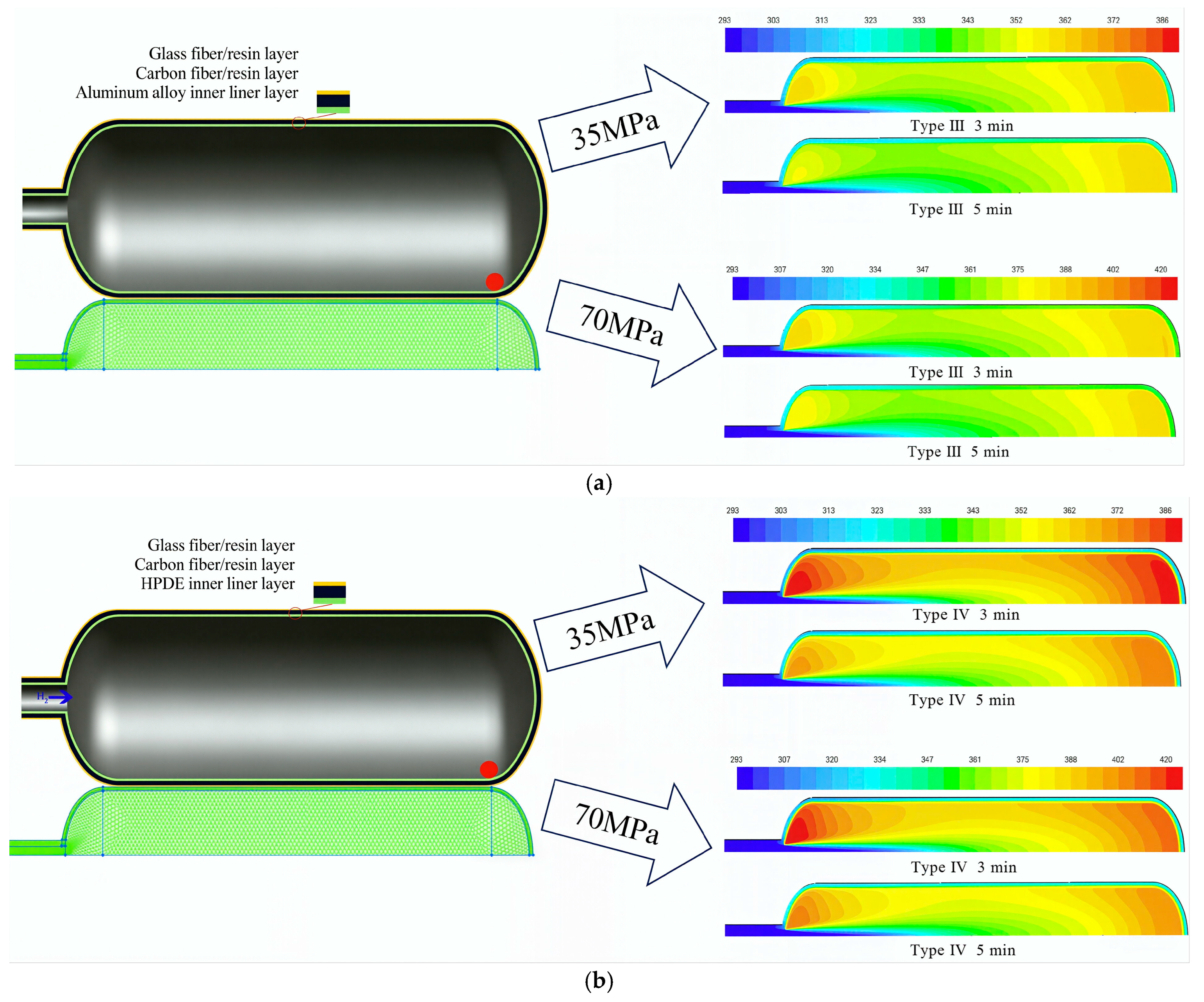
A 2D simulation model is established by projecting the hydrogen storage device onto a 2D plane, ignoring geometric and physical variations in one spatial dimension. 2D models are suitable for research objects with regular symmetry and no significant variations in physical quantities along a single direction during high-pressure hydrogen charging. The 2D axisymmetric CFD models for Type III and Type IV hydrogen storage and transportation devices were established by Zheng’s team from Zhejiang University. Considering the real gas equation of state, the influences of the hydrogen filling time, pressurization mode, liner material, and thickness of the carbon fiber epoxy composite on the thermodynamic characteristics of hydrogen storage devices during the filling process were numerically investigated [31,32,33,34]. The simulation results of Type III and Type IV hydrogen storage are compared in Figure 1. It can be seen from Figure 1 that the temperature rise in hydrogen gas in the Type IV cylinder is significantly higher than that in the Type III cylinder. A 2D axisymmetric swirling CFD model was established by Zhou’s team from Nanjing Tech University. Real gas behavior, compressible unsteady viscous flow, and heat transfer effects were considered. The influences of the tank aspect ratio, inlet diameter, and variable mass flow rate on the temperature rise inside the tank were investigated. It was revealed that a small aspect ratio, large inlet diameter, and increasing mass flow rate are more favorable for temperature rise control [35]. A 2D axisymmetric model for Type III and Type IV hydrogen storage tanks at 70 MPa under a constant mass flow rate was developed by Monteiro, Pinto, and co-workers from the Polytechnic Institute [36]. The effects of the inlet initial temperature, mass flow rate, and material properties on the temperature, pressure, and velocity inside the tanks were analyzed. The compression effect of high-speed inlet gas flow was quantitatively evaluated for the first time. B. Dicken and W. Merida et al. established a 2D axisymmetric CFD model for Type III hydrogen storage tanks. Compressible unsteady viscous flow, real gas effects, heat transfer from gas to tank wall, and heat conduction through the wall to the environment were taken into account. Thermodynamic simulation clearly revealed the temperature gradient distribution inside the tank. The optimal temperature measurement region was determined. The final average gas temperature at the end of filling was accurately predicted [37]. A 2D axisymmetric CFD model for Type IV hydrogen storage devices with a pressure of 70 MPa and a volume exceeding 300 L was developed by Li and Wang et al. [38]. The temperature rise characteristics during fast filling were investigated. The influences of the filling rate, ambient temperature, tank volume, and hydrogen inlet temperature on the internal temperature rise were examined. The effects of the inlet pressurization mode and precooling method on the temperature rise in large-volume Type IV tanks were analyzed. The numerical simulations using a two-dimensional axisymmetric model for a 70 MPa marine Type III high-pressure hydrogen storage tank were conducted by Cui and Yuan et al. [39]. The influences of the aspect ratio, inlet diameter, and inlet pipe length on the temperature rise during filling were discussed. A comprehensive study on hydrogen charging and discharging processes for 70 MPa on-board Type III and Type IV hydrogen cylinders was performed based on two-dimensional axisymmetric CFD models by Zhang and Zhou et al. [40]. The effects of the charge/discharge rate, source temperature, ambient temperature, and residual pressure on cylinder temperature evolution were explored.
2D CFD simulation has high computational efficiency, but it cannot accurately reproduce the complex flow field and temperature stratification in the actual filling process. Studies have shown that 2D axisymmetric models underestimate the local high temperature at the top of the tank by 10–15 °C, and cannot simulate the asymmetric flow caused by the inlet structure and pipeline layout. Different research teams use different turbulence models and real gas state equations, resulting in a maximum difference of 20% in the simulation results of the same working condition. This method is only suitable for preliminary parameter optimization, and cannot be used for the final safety certification of hydrogen storage devices.

3.2. 3D CFD Simulation

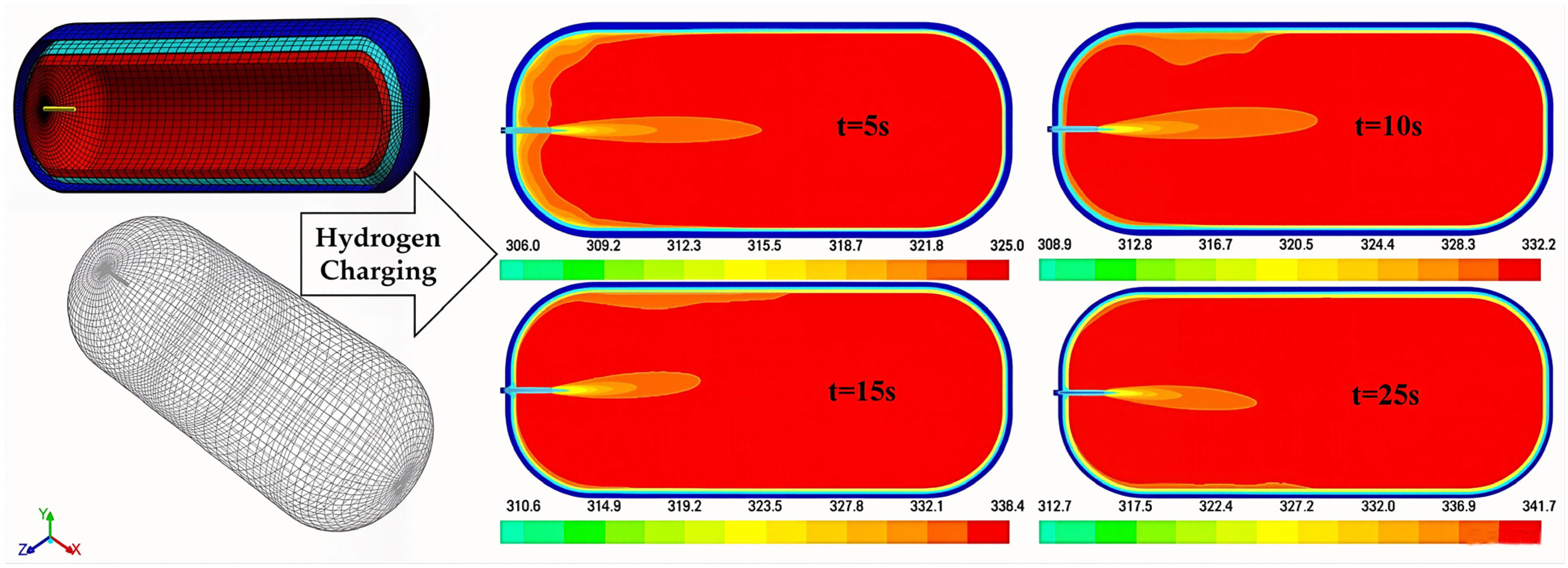
3D simulation models take all three spatial dimensions into account. They fully reproduce the geometric structure of the research object and the variations in physical parameters in all spatial directions. They are suitable for simulation objects with complex geometry, irregular symmetry, and significant gradient changes in physical quantities in multiple directions during high-pressure hydrogen charging. The CFD method combined with conjugate heat transfer and the real gas equation of state was adopted by D. Baraldi’s team from the Institute for Energy and Transport, Joint Research Centre of the European Commission. Three computational domains, namely gas, liner, and external insulation, were modeled separately [41,42,43,44,45]. Full-scale and half-scale 3D geometric models were established for Type III and Type IV hydrogen storage devices. The influences of the hydrogen filling time, tank material, Joule–Thomson effect, thermal insulation, pressurization rate, initial tank pressure, and external insulation material on the internal temperature of hydrogen storage tanks were systematically investigated. The 3D CFD models for Type III and Type IV hydrogen storage devices were established by Suryan, Kim et al. [46]. Transient, compressible, viscous flow, real gas effects, heat transfer between gas and tank wall, and heat conduction from the wall to the ambient environment were considered. The effects of the ambient temperature, initial gas temperature, and inlet temperature on the filling process were analyzed. As shown in Figure 2, the local temperature distribution inside the tank at different filling stages was obtained. It indicated that the temperature field exhibited asymmetry during the filling process. The 2D and 3D CFD models for Type III hydrogen storage devices were constructed combining the k−ε turbulence model and the Redlich–Kwong equation of state by Mokhtari et al. [47]. Thermodynamic phenomena of hydrogen during complex filling operations were explored through numerical simulation. The effects of the hydrogen pressure fluctuation, filling duration, and temperature variation on the overall efficiency and safety indicators of the filling process were studied. The results showed that 3D CFD simulation models could accurately predict the temperature distribution. Compared with 2D models, 3D models could realistically reproduce the flow field evolution during hydrogen charging and achieve a higher simulation accuracy. However, 3D simulation involves a large computational cost and long calculation time, making it difficult to balance both accuracy and efficiency in CFD analysis.
3D CFD simulation has the highest accuracy and can fully reproduce the multi-physical field evolution in the filling process, but its computational cost is huge and time-consuming. Most studies use simplified geometric models and ignore the influence of valves and pipelines, leading to differences between simulation results and actual working conditions. In addition, the thermophysical parameter database of high-pressure hydrogen is not perfect, and the prediction error under extreme working conditions (80 MPa, 3 min fast filling) exceeds 8%. The comparison of 2D and 3D CFD simulations is listed in Table 2. It can be seen from Table 2 that there is an obvious trade-off between efficiency and accuracy in CFD simulation. 2D axisymmetric models are cost-effective and suitable for large-scale parameter studies and early-stage design optimization. However, they fail to reproduce the actual 3D flow and temperature stratification inside the tank, which may underestimate local hotspots. 3D CFD models can fully capture the thermodynamic field distribution and are necessary for safety assessment and detailed design. For practical engineering, a two-step strategy is recommended: use 2D CFD for rapid screening, then apply 3D CFD for key condition verification.
Current CFD simulations of rapid hydrogen filling can reveal the multi-physics field evolution mechanism during the charging process and achieve the quantitative analysis of key performances. They provide fluid mechanics support for the research of hydrogen charging systems. However, relatively large simulation errors exist under complex working conditions. Meanwhile, the prediction accuracy is limited by the measured data. In addition, refined CFD simulations require large computational resources, a long calculation time and high cost. Therefore, the CFD simulation method needs to be improved and the computational efficiency should be optimized.

4. Experimental Studies on High-Pressure Gaseous Hydrogen Filling

High-pressure hydrogen charging experiments represent one of the most important approaches to investigate the thermodynamic behaviors of hydrogen storage devices. By conducting high-pressure hydrogen charging of storage vessels in a controlled environment, actual hydrogen storage processes can be faithfully simulated. In this way, the evolution laws of key parameters can be quantified, and the accuracy of theoretical thermodynamic analysis and CFD simulation models can be validated. These efforts effectively promote the application and popularization of high-pressure gaseous hydrogen storage technology in the hydrogen energy industry.
As early as 1958, scholars worldwide began to investigate the thermodynamic performance of hydrogen storage devices through high-pressure charging experiments [48]. Since then, thermodynamic experimental studies on the charging process of high-pressure hydrogen storage devices have been gradually carried out. Although numerous thermodynamic data under real working conditions were obtained from experimental studies on fast-filling operations in the late 20th century, most of these experiments were focused on Type I and Type II hydrogen storage devices [49,50,51,52,53]. After the year 2000, Type I and Type II hydrogen storage devices, which suffer from heavy weight, low storage efficiency, and high safety risks, were gradually replaced by lightweight, high-density, safe, and stable Type III and Type IV hydrogen storage devices. Due to differences in materials and experimental conditions, research findings obtained from Type I and Type II storage devices cannot be directly applied to Type III and Type IV vessels.
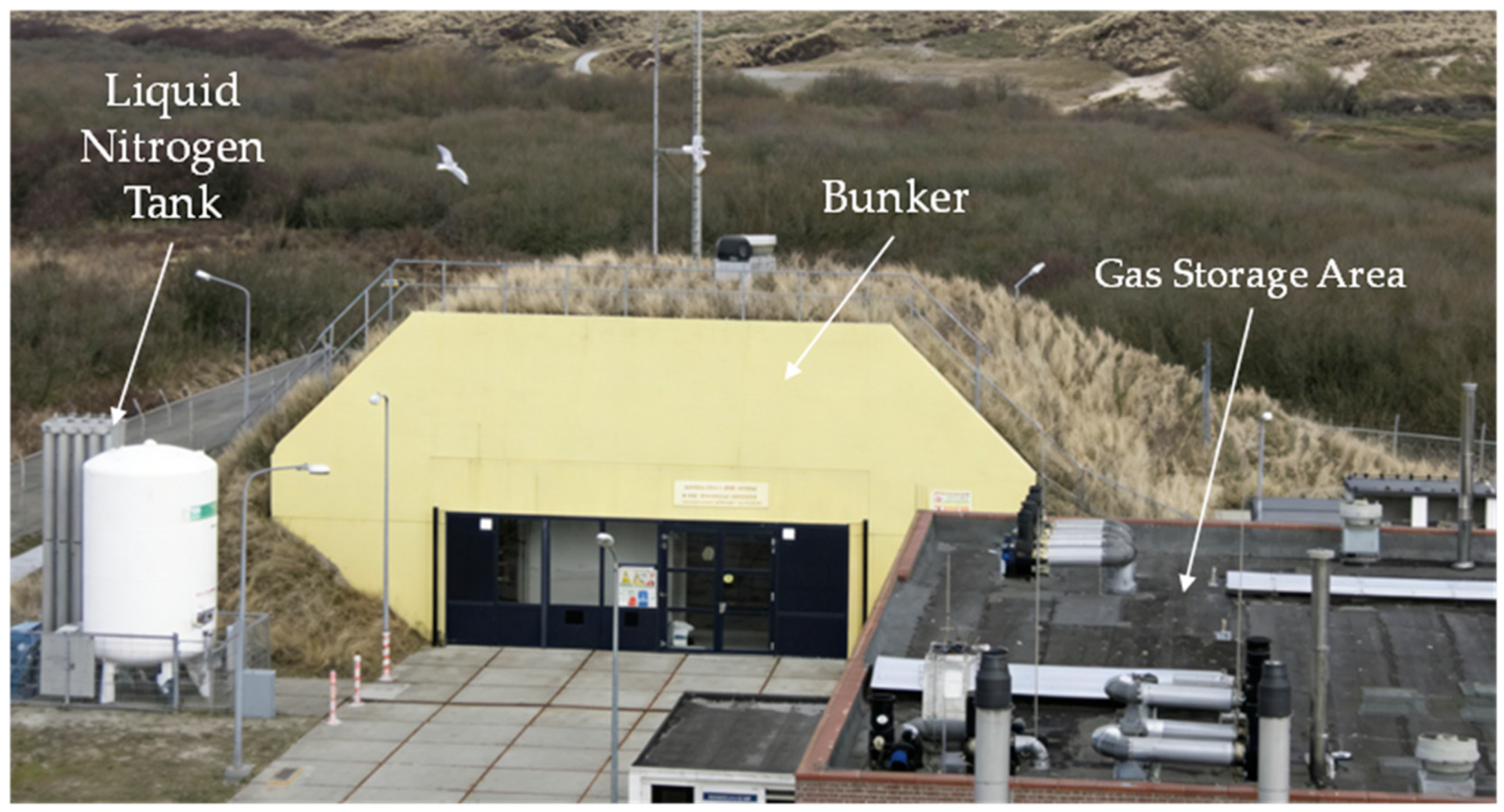
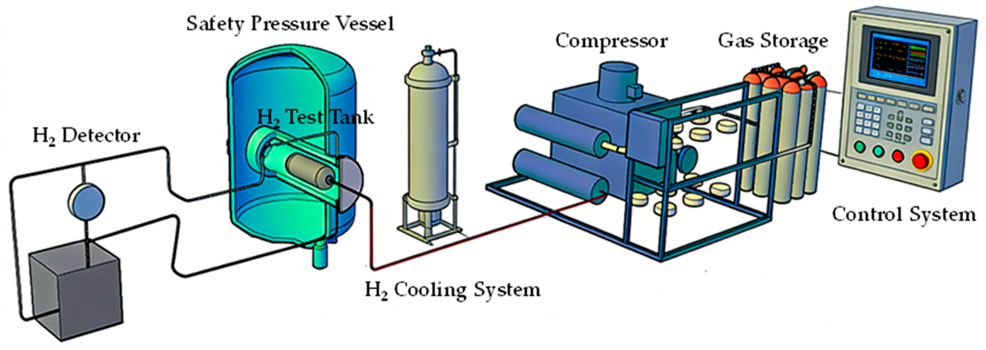
Therefore, scholars worldwide have established new experimental platforms to investigate the thermodynamic behaviors of Type III and Type IV high-pressure hydrogen storage devices during charging. Among these newly built platforms, the Gas Tank Testing Facility (GasTeF) was constructed earlier. It was completed in June 2006 at the Joint Research Centre in Petten, the Netherlands, by the Institute for Energy and Transport (JRC-IET) of the European Commission [54]. This test facility allows performance verification tests on full-scale high-pressure on-board storage tanks for hydrogen or natural gas, as well as any other high-pressure components such as valves and pipelines. It is designed to simulate the working environment of high-pressure hydrogen storage and transportation, and to evaluate the efficiency, safety, environmental impact, and reliability of hydrogen technologies. The GasTeF consists of a semi-buried underground concrete bunker, an open-air auxiliary gas storage area and the liquid nitrogen tank, as shown in Figure 3. The bunker is built with double-layer concrete walls and a 3 m thick sand layer, which can withstand an explosion energy equivalent to 50 kg of TNT, with a safety factor of 10. The bunker is divided into three sections: a service room, a compressor room, and a test room. The compressor room is equipped with a two-stage compressor, which can pressurize and depressurize the test tank (i.e., charging and discharging), with a maximum filling pressure of 88 MPa. The test room contains a pressure vessel that can house the components to be tested. Inside the pressure vessel, a sleeve is installed, and the test component is placed in the sleeve. The sleeve is filled with an inert gas (helium or nitrogen) to prevent explosions or fires caused by hydrogen leakage. The sleeve is also equipped with a gas chromatograph and two hydrogen detectors to detect and quantify possible hydrogen permeation from the test component. The open-air auxiliary gas storage area consists of standard cylinder banks with a pressure of approximately 28 MPa. These cylinders are connected to the compressor in the compressor room via pipelines. For filling experiments, the compressor is first bypassed, and the storage tank (or component) is directly filled from the gas storage facility. The compressor then takes over to raise the pressure of the tank (or component) to the desired value. For discharging experiments, the gas first flows directly from the tank (or component) to the gas storage facility, bypassing the compressor. Once the pressure between the tank (or component) and the storage facility reaches equilibrium, the compressor starts to pump gas from the tank (or component) into the storage facility until the set final discharge pressure is achieved. Thermocouples, pressure sensors, and other measuring instruments are installed in the test tank (or component) to monitor the variations in temperature and pressure during charging/discharging cycles [55]. The test system of GasTeF is shown as Figure 4.
The first results of hydrogen charging/discharging cycle experiments on Type IV tanks using this platform show that when the tank is rapidly charged within 2–5 min, the maximum temperature may exceed the limit of 85 °C, but the gas temperature inside the tank can drop below 85 °C within a relatively short time. During the filling process, the measured temperature inside the tank is fairly uniform [56]. After charging, a temperature stratification appears, with a higher temperature at the top of the tank. After six charging/discharging cycles, the temperature of the hydrogen storage tank stabilizes at 23 °C. The tank pressure drops sharply within the initial 30 min and reaches an equilibrium pressure of 30 MPa after 1.5 h [57].
In addition, ET Energie Technologie GmbH in Munich, Germany, has designed and constructed three test chambers for the hydrogen cycling and permeability testing of storage systems and components [58]. This test facility can test full-scale hydrogen storage tanks at different ambient temperatures ranging from −40 °C to 85 °C. The hydrogen temperature is controlled between −40 °C and 85 °C, with a maximum filling rate of 60 g/s. Maximator and TesTneT of Germany have built a laboratory for hydrogen pneumatic cycling tests in Garching near Munich. The laboratory is equipped with explosion-proof chambers for testing pre-damaged or newly designed vessels [59]. This facility can test tanks with an internal volume up to 150 L and a maximum pressure of 105 MPa. CSA Testing & Certification Inc. and Powertech of Canada have established facilities for hydrogen cycling tests [60]. These facilities can perform pneumatic pressure cycling tests using precooled hydrogen at a maximum pressure of 95 MPa, as well as permeability or leakage tests at ambient temperatures from −40 °C to 85 °C. Japan constructed the Hydrogen and Fuel Cell Vehicle Safety Evaluation Facility (HySEF) in 2007. This facility is equipped with high-pressure hydrogen filling test equipment [61]. Hydrogen filling cycle tests and permeability measurements can be conducted on large-scale high-pressure tanks with volumes up to 260 L and pressures of 70 MPa in a temperature-controlled environment ranging from −40 °C to 85 °C. The Beijing Institute of Aeronautical Testing Technology owns a hydrogen environment fatigue test system [62]. The system includes an 80 MPa high-pressure storage vessel, which can fill up to five tanks with a maximum volume of 100 L simultaneously. The maximum test pressure of the system is 70 MPa, and the maximum mass flow rate is 3.24 kg/min.
Existing experimental platforms are mostly built for small and medium-sized hydrogen storage tanks, and there is a lack of large-scale (≥300 L) storage device test systems. The GasTeF platform in Europe and HySEF platform in Japan have high test accuracy, but their test conditions are single and cannot cover extreme environments such as a low temperature and high altitude. Domestic experimental platforms have problems such as an uneven measuring point layout and low sensor precision, resulting in poor repeatability of experimental data. In addition, there is no unified experimental standard, leading to incomparable data from different platforms, which restricts the verification of theoretical models.
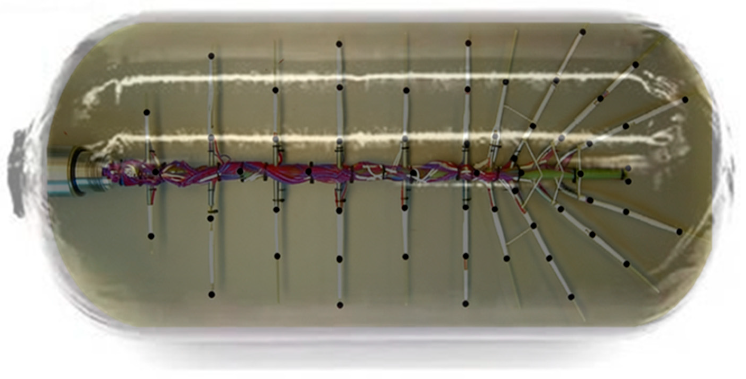
With the development of experimental techniques and the reduction in costs, scholars worldwide have designed and conducted numerous high-pressure hydrogen charging experiments based on existing technologies and equipment. Rapid hydrogen filling temperature rise tests, temperature distribution tests, and cyclic hydrogen charging–discharging tests on Type III hydrogen storage devices were carried out by Zheng’s team from Zhejiang University. Sixteen internal measuring points and five external wall measuring points were used. The influences of the initial pressure, ambient temperature, and other factors on the temperature rise were systematically studied. The results showed that the temperature rise increased with a lower initial pressure and higher filling rate. The filling time and discharge flow rate affected the temperatures after charging and discharging, respectively [26,63,64]. Hydrogen filling tests and cyclic charging–discharging tests on Type III and Type IV storage devices were conducted using the GasTeF platform by D.Baraldi’s team from the Institute for Energy and Transport of the European Commission [65,66]. The effects of different initial temperatures on the filling process and thermal behavior during full cycles were studied. The results showed that the final gas temperature increased linearly with the initial tank temperature. A faster filling rate leads to a greater temperature rise. Meanwhile, the temperature rise in Type IV devices was higher than that in Type III devices. Heat transfer and temperature rise experiments during rapid high-pressure hydrogen filling were performed by Kadode Masanori’s team from Saga University [14]. The gas and tank wall temperatures were measured simultaneously to investigate gas–solid coupled heat transfer. A lumped parameter model was proposed to estimate the temperature variation. The results showed that the hydrogen temperature first increased and then decreased, with a significant temperature rise at a high pressure and high flow rate. Thermal insulation increased the hydrogen temperature by 20 °C. Experimental studies under various filling conditions using a 90.5 L Type IV storage tank were conducted by Thomas Bourgeois et al. [20]. Temperature sensors were used to monitor the gas temperature in real time during filling. The results showed that heat transfer between gas and the tank wall was dominated only by forced convection, and the effect of natural convection was negligible. Sixty-three thermocouples (as shown in Figure 5) were arranged inside a Type III hydrogen tank for compressed hydrogen filling experiments by Dicken and Merida et al. [30]. The 3D temperature field during filling was accurately obtained. Based on the experimental results, the influences of the filling duration and initial mass on temperature stratification were revealed. A hydrogen medium fatigue system simulating real charging and discharging conditions was established by Zhang and Wang et al. [62]. Thermodynamic pressure coupled cyclic loads were applied. The fatigue performance of Type III hydrogen storage vessels in a real hydrogen environment was studied through high-pressure fatigue tests. The results showed that the ultimate strength of the tank decreased by 15% after 500 cycles, and the fatigue life was 5122 cycles. Failure occurs by leakage rather than burst. High-precision and repeatable tests were performed based on an explosion-proof chamber facility by Watanabe et al. [65]. Comparative fire tests, flame exposure tests, and high-pressure hydrogen filling tests on hydrogen tanks were carried out. The effects of different fire sources on storage tanks were investigated, overcoming the limitations of outdoor tests. Temperature characteristic experiments on Type IV hydrogen tanks under various initial pressures were conducted by Kim and Kee et al. [67]. Experimental and 3D transient CFD simulations were combined, considering gas–solid conjugate heat transfer. The influence of the initial pressure from 0 to 20 MPa on the filling temperature was explored. The buoyancy mechanism of the temperature difference inside the tank was revealed. A self-designed multi-point umbrella-shaped temperature measurement bracket was used by Li and Yang et al. [68]. Thirteen T-type thermocouples were applied to measure the temperature variation during the fast filling of Type III hydrogen cylinders. The influences of key parameters, including the initial pressure, initial hydrogen temperature, and filling rate, on the temperature rise were investigated. The results showed that the temperature inside the cylinder increased with a lower initial pressure, higher ambient temperature, and shorter filling time. Based on the above experimental results, the main factors affecting the temperature rise and pressure dynamics during hydrogen charging include the initial pressure, inlet temperature, ambient temperature, mass flow rate, filling time, and tank material. Their quantitative influence is summarized in Table 3. As shown in Table 3, the initial pressure and mass flow rate exert the most prominent effects on thermal and pressure responses. The inlet temperature and tank material properties also serve as critical controllable variables. Reasonable parameter matching and targeted regulation are essential to suppress overheating and ensure the operational safety of high-pressure hydrogen charging.
Despite differences in facilities and conditions, consistent trends have been observed across most experiments: Rapid filling within 3–5 min causes a sharp temperature increase, frequently exceeding 85 °C. The temperature first rises rapidly during filling, then decreases slowly after filling stops. After filling, obvious temperature stratification appears inside the vessel, with a higher temperature at the top and lower temperature near the bottom. The pressure increases almost linearly during filling. After filling, the pressure drops rapidly in the first 30 min and then gradually stabilizes. Type IV tanks generally show a higher temperature rise than Type III tanks under the same filling conditions, due to the lower thermal conductivity of plastic liners. The temperature rise increases with a lower initial pressure, higher mass flow rate, higher inlet temperature, and higher ambient temperature.
Most experiments focus on Type III and Type IV hydrogen storage tanks, but there are obvious contradictions in the research on the temperature rise difference between the two types of tanks. Some studies show that Type IV tanks have a higher temperature rise, while others hold the opposite view, which is mainly caused by differences in liner materials and test conditions. In addition, existing experiments rarely consider the coupling effect of multiple factors (ambient temperature + initial pressure + filling rate), and the obtained laws are not universal. The experimental data of large-scale storage devices are extremely scarce, which cannot support the engineering application of large-scale hydrogen storage and transportation.
Existing experimental conclusions have provided direct guidance for practical engineering implications. To control the temperature below 85 °C, precooling or a reduced mass flow rate is necessary for 70 MPa fast filling. Type IV tanks need stricter thermal management due to a higher temperature rise. The initial pressure should be kept at a moderate level to balance temperature control and hydrogen capacity. However, current experimental investigations mainly focus on small-scale hydrogen storage devices. Data for large-scale stationary hydrogen storage devices are scarce. Most studies only analyze single factors such as the initial pressure or ambient temperature. Multi-factor coupling experiments are rare. In addition, few experiments focus on long-cycle repeated filling–depletion processes, which are critical for actual service life evaluation. Moreover, most experiments ignore the influence of the pipeline layout, valve structure, and on-board vibration, leading to differences from real working conditions.

5. Thermal Management Strategies for Rapid Hydrogen Charging

According to ISO/DIS 15869 [69], ISO 19881:2018 [70], ISO 19880-8:2024 [71], GB/T 35544-2025 [72], GB/T 42612-2023 [73], and GB 50156-2021 [74], the maximum temperature of hydrogen shall not exceed 85 °C during the charging process of compressed hydrogen storage. However, due to the short charging time and high charging rate, the hydrogen temperature rises sharply in actual charging operations. To meet the requirements of a short filling time, high filling rate, high safety and reliability, the implementation of effective thermal management strategies is critical. At present, the thermal management strategies for rapid hydrogen charging mainly include the following: precooling (including hydrogen precooling and liner precooling), variable-rate hydrogen charging, and multi-stage initial pressure charging (or multi-stage filling).

5.1. Precooling Technology

Precooling technology reduces the initial temperature of hydrogen (or the liner) before charging to counteract the heat generated during rapid charging, so that the final temperature inside the storage device can be controlled within a safe range, thereby realizing rapid hydrogen refueling. On the premise of ensuring charging safety, precooling technology can improve the refueling efficiency and hydrogen density. A 2D CFD model for precooled Type IV hydrogen storage tanks was established by D. Baraldi’s team from the Institute for Energy and Transport, Joint Research Centre of the European Commission [75,76]. The effects of different precooling temperatures on the average mass flow rate, hydrogen storage density ratio, and total mass of gas inside the tank were investigated. The findings broke through the traditional understanding of full-time precooling and confirmed that temperature control can be achieved with partial-time precooling. Hydrogen refueling experiments on 70 MPa on-board storage tanks were conducted by Cebolla, Miguel et al. [77]. The effects of the inlet hydrogen precooling temperature and mass flow rate on the final state of charge (SOC) were explored, and the thermal characteristics of Type III and Type IV tanks were compared. The results showed that the inlet precooling temperature had the most significant effect on the SOC, and Type IV tanks were more sensitive. Precooling could reduce the negative impact of the mass flow rate on the SOC, and the optimal energy efficiency was achieved at −40 °C precooling.
An analytical solution for the hydrogen precooling temperature based on a simplified lumped parameter model was derived by Xiao’s team from the Wuhan University of Technology [78]. A correlation formula was established between the precooling temperature, initial temperature/pressure, and charging duration, and the scenarios requiring hydrogen precooling were identified. It was proved that hydrogen precooling is necessary when the actual initial temperature is higher than the critical initial temperature, the actual initial pressure is lower than the critical initial pressure, or the actual refueling time is shorter than the critical refueling time. A numerical simulation model for the rapid charging process of 70 MPa Type III on-board hydrogen cylinders with metal liners was developed by Wang, Chen and colleagues from Zhejiang University [79]. Based on numerical analysis, a precooled charging technology was proposed, verifying that hydrogen precooling was an effective method to reduce the maximum cylinder temperature and improve the SOC during rapid charging. The heat transfer performance of a shell-and-tube heat exchanger using petal-shaped baffles was optimized by Li, Wang and co-workers from the Xi’an University of Architecture and Technology [80]. A two-dimensional axisymmetric CFD model of the heat exchanger was established to systematically investigate the effects of the hydrogen inlet temperature/pressure and refrigerant flow rate on precooling performance. The results showed that the hydrogen inlet temperature and refrigerant flow rate had more significant influences on the precooling effect. The outlet temperature rose slightly with a higher hydrogen inlet pressure, and a higher refrigerant flow rate led to a better precooling performance. A non-destructive cryogenic compressed hydrogen filling system at liquid nitrogen temperature was built by He, Lv and colleagues from the University of Chinese Academy of Sciences [81]. An elbow inlet structure was adopted to achieve the rapid diffusion of low-temperature hydrogen and improve the uniformity of temperature distribution. The results showed that the temperature field of the elbow was much more uniform than that of the straight pipe, while the straight pipe cooled faster in the later stage. The effects of the precooling parameters on hydrogen charging for heavy-duty 350 L Type IV storage devices was investigated by Nejc and co-workers from the Graz University of Technology [82]. An adjustable precooling control strategy combining the flow splitting ratio and cooling delay was proposed, overcoming the limitation of fixed precooling. The results showed that cooling energy consumption could be reduced by more than 50% after optimization. A dynamic simulation model for hydrogen precooling with compact heat exchangers in a three-stage hydrogen refueling station was established by Yang, Wang and colleagues from Shanghai Jiao Tong University [83]. A staged precooling mode (initial/final stage) was proposed, and a precooling parameter optimization algorithm was developed aiming at a low final temperature, high SOC, and low energy consumption. In addition to hydrogen precooling, a passive scheme based on liner precooling and thermal property modification, together with an active scheme of precooling on-board system components, was proposed by Aguilera et al. [84]. The on-board thermal management system was used to precool the liner and end caps in contact with hydrogen before and during charging. Experimental verification and CFD simulation were carried out. The results showed that precooling the liner and end caps could achieve a lower final hydrogen temperature. The energy consumption of liner precooling was 42%~68% lower than that of hydrogen precooling. Therefore, precooling the liner and end caps provided a robust and efficient alternative to hydrogen precooling.
Precooling technology is the most widely used thermal management method at present, but it has obvious defects. Hydrogen precooling requires additional refrigeration equipment, which increases energy consumption by 30–50% and the construction costs. Liner precooling has a lower energy consumption, but it is difficult to realize on-board hydrogen storage systems. Studies have shown that the optimal precooling temperature is inconsistent under different working conditions, and there is a contradiction between the temperature control effect and energy efficiency. In addition, full-process precooling is not energy-saving, but partial-process precooling lacks mature control strategies, which limits its large-scale application.

5.2. Variable-Rate Hydrogen Charging

Variable-rate hydrogen charging technology dynamically adjusts the refueling rate in stages via a control system based on real-time temperature and pressure feedback from the hydrogen storage device. Following the SAE J2601 standard [84], it avoids an uncontrolled temperature rise caused by constant-rate charging. This technology enables accurate temperature control, balances the charging speed and safety, and effectively improves system reliability. A variable-rate charging strategy was proposed by Zheng’s team from Zhejiang University. In this strategy, the mass charging rate was regulated by this strategy based on the pressure ratio between the storage tank and the source container [32,64]. A thermodynamic model for hydrogen charging was established to quantitatively reveal the relationship between the pressure ratio and the charging rate. Thermodynamic responses under different pressurization modes and charging durations were systematically analyzed. The results showed that temperature control could be achieved only by adjusting the process parameters without precooling. The temperature rise increased with a higher charging rate and lower initial pressure. A novel variable mass flow rate hydrogen refueling strategy was proposed based on a thermodynamic model of the storage tank by Li, Yang and co-workers from the Beijing Institute of Technology [29]. The strategy comprehensively considered the hydrogen filling rate, temperature rise in the hydrogen zone, and refueling time to resolve the contradiction among the temperature/pressure rise and total hydrogen mass. A deep reinforcement learning algorithm was applied to the refueling strategy design, which can achieve the maximum hydrogen filling within specified time limits and under temperature and pressure constraints. Progressive and multi-stage mass flow rate charging strategies were proposed by Ma from Hanyang University, which were classified into increasing and decreasing types [85]. Through comparative analysis of 16 variable-rate charging schemes, the temperature rise characteristics of increasing and decreasing strategies were clarified. The results showed that the decreasing strategy was superior, as it reduced the maximum temperature, shortened the charging time, and improved the uniformity of temperature distribution.
Variable-rate charging can effectively control the temperature rise without precooling, but it has high requirements for control system and sensor precision. Most studies adopt a decreasing flow rate strategy, but there is a lack of a unified standard for the flow rate adjustment node. The reinforcement learning-based strategy has high intelligence, but its computational complexity is high and it is difficult to realize real-time control. In addition, this technology prolongs the filling time while controlling the temperature, which is difficult to meet the demand of 3–5 min fast filling in hydrogen refueling stations. The reliability of variable-rate charging under extreme working conditions has not been fully verified.

5.3. Multi-Stage Charging Technology

Multi-stage charging technology refers to a method that charges hydrogen storage devices in stages according to a pressure gradient. Gas is supplied sequentially from low-, medium-, and high-pressure hydrogen storage devices or compressor stages based on preset switching pressures. Combined with temperature feedback and precooling, safe and rapid charging is realized. Multi-stage charging technology makes full use of graded hydrogen storage and residual pressure between stages, thus improving the charging rate. The optimization research on the hydrogen utilization efficiency at refueling stations was carried out based on the pressure-balanced charging method by Zheng’s team from Zhejiang University [86]. Hydrogen utilization efficiencies under single-stage, dual-stage, and three-stage charging modes were analyzed. The results showed that the hydrogen utilization efficiency of the multi-stage charging mode was significantly higher than that of the single-stage mode. A validated dynamic simulation model for multi-stage hydrogen refueling was developed by E. Rothuizen from the Technical University of Denmark [87]. Real gas behavior, 1D unsteady heat transfer, and the thermodynamic effects of vehicle-side pressure loss were considered. The results showed that multi-stage refueling was more energy-efficient than single-tank refueling, and vehicle-side pressure loss prolonged the charging time. To overcome the high energy consumption defect of single-stage hydrogen storage, a multi-stage hydrogen storage system with no more than three stages was designed by Zheng’s team [88]. A dynamic simulation model including the whole process of charging, pressure control, precooling, and venting was established, which can simulate the evolution of the hydrogen state and accurately calculate energy consumption. The results showed that the total energy consumption of the system decreased with the increase in storage stages. Compared with the single-stage system, the three-stage system reduced total energy consumption by 50.9% and hydrogen circulation by 29.7%. Multi-stage charging improves the hydrogen utilization efficiency and filling speed, but its system structure is complex and occupies a large area. The three-stage system can reduce energy consumption by 50.9% compared with the single-stage system, but it requires more storage tanks and valves, increasing the maintenance costs. Most studies focus on hydrogen refueling stations, and there is a lack of research on on-board multi-stage charging. In addition, the pressure switching strategy of multi-stage charging is not optimized, and there is a contradiction between the filling efficiency and pressure balance. The large-scale popularization of this technology faces severe cost and control challenges.
Based on the performance of various thermal management strategies under actual operating conditions, the practical limitations and applicable scenarios are compared in Table 4. It can be seen from Table 4 that precooling is the most reliable and widely applied, but is limited by high cost and energy consumption. Variable-rate charging is energy-efficient but struggles to meet strict fast-filling requirements. Multi-stage charging improves the station economy but has limited temperature control ability.
In addition, different thermal management strategies are compared in Table 5. As shown in Table 5, precooling provides the most stable temperature control and is currently the industrial standard, but it increases energy consumption and equipment investment. Variable-rate filling achieves temperature control without cooling equipment, making it energy-efficient, but it requires high-precision real-time control. Multi-stage filling improves hydrogen utilization but relies on a complex station system. For general hydrogen refueling stations, precooling combined with variable-rate filling is the optimal practical solution. For large-scale or heavy-duty applications, multi-stage charging integrated with precooling is more advantageous.
Existing studies have shown that the above thermal management strategies for rapid hydrogen charging can achieve satisfactory temperature rise control effects. However, the current thermal management strategies suffer from complex system structures, difficulties in precise control, and high construction and maintenance costs, which limit their widespread application. Therefore, it is necessary to deeply integrate cutting-edge technologies such as artificial intelligence, automatic control, and cost management to develop a concise-structured, easily controlled, and cost-effective thermal management scheme for rapid hydrogen charging, so as to provide core support for the large-scale application of rapid hydrogen charging technology.

6. Research Prospects

Research on the high-pressure gaseous charging process of hydrogen storage devices began in the mid-20th century and matured from the late 20th century to the early 21st century. With increasing investment and support in the hydrogen energy field from governments and enterprises worldwide, high-pressure gaseous hydrogen charging technology has advanced continuously and been commercially applied in fuel cell vehicles, ushering in new development opportunities. Although existing studies have covered many aspects of rapid hydrogen filling, a certain gap still exists before the large-scale application of this technology. To systematically sort out the research progress, core conclusions, and existing differences in representative studies, this paper summarizes key findings from the typical literature in Table 6. This comparison intuitively presents the research status, methodological characteristics, and consensus or divergence in the field of hydrogen charging thermodynamics.
As shown in Table 6, current studies have formed a relatively complete research system covering theoretical models, numerical simulations, experimental tests, and control strategies. Most studies consistently confirm that the initial pressure, mass flow rate, and inlet temperature are dominant factors influencing the temperature rise, and Type IV tanks are more sensitive to thermal behaviors. However, obvious differences exist in modeling accuracy, experimental conditions, thermal management efficiency, and application scope among different studies. These inconsistencies and limitations directly restrict the unified design, standardization, and large-scale application of hydrogen charging technology. On this basis, further research should be carried out in the following aspects:
(1) Current thermodynamic theoretical analyses have clearly revealed the thermodynamic behaviors during rapid hydrogen filling through mathematical models. However, due to the large differences in storage device structures and numerous influencing factors, a comprehensive mathematical model that fully considers various factors for different storage devices has not yet been established. Therefore, it is necessary to comprehensively integrate dynamic parameters, geometric parameters, material parameters, and operating parameters to construct a unified thermodynamic theoretical model for hydrogen filling, so as to achieve the efficient and accurate analysis of pressure–temperature–mass variations during the charging process.
(2) Existing CFD simulations of rapid hydrogen filling can effectively simulate the thermodynamic responses during rapid charging. Nevertheless, the thermophysical properties of hydrogen (density, specific heat capacity, thermal conductivity) exhibit nonlinear variations under high pressure, the accuracy of current databases is limited, and the accuracy of hydrogen parameters is insufficient. Meanwhile, the computational cost of refined simulation increases exponentially, leading to a prominent contradiction between accuracy and computational efficiency. Therefore, it is necessary to consider the nonlinearity of hydrogen thermophysics, combine machine learning/deep learning techniques, develop intelligent CFD simulation models and high-precision, high-efficiency algorithms, and establish an efficient and reliable hydrogen charging simulation system.
(3) Corresponding rapid hydrogen charging temperature rise experiments and cyclic hydrogen charging–discharging experiments have effectively promoted the progress of thermodynamic theories and numerical simulation technologies for high-pressure gaseous hydrogen charging. However, current rapid charging experiments usually adopt self-defined settings in core aspects such as site selection, test conditions, equipment specifications, and test methods, lacking unified and authoritative standard specifications. Therefore, it is essential to formulate corresponding experimental standards/specifications for high-pressure gaseous hydrogen charging, providing clear, unified, and safe guidelines for the research, development, testing, and application of high-pressure rapid gaseous hydrogen charging technology, and strongly supporting its large-scale deployment.
(4) Most existing studies on rapid hydrogen filling focus on the individual effects of the ambient temperature, initial pressure, and mass flow rate on the final temperature, pressure, and mass of hydrogen. However, the temperature, pressure, and other responses of the storage device during charging result from multi-parameter coupling effects. Therefore, future research should conduct theoretical analyses, simulations, and experimental tests on the thermodynamic behaviors of hydrogen storage devices under multi-factor coupled conditions.
(5) At present, thermal management methods for rapid hydrogen charging mainly consider individual strategies such as precooling, variable-rate charging, and multi-stage charging. Future research can focus on the coupled application of these three strategies. By integrating precooling, the charging rate, and multi-stage charging, an optimal thermal management scheme for rapid hydrogen charging can be developed to achieve multiple objectives including the fast charging of, temperature control of, cost reduction in, and efficiency improvement in hydrogen storage devices. While reducing the temperature rise, the scheme will further enhance efficiency, lower energy consumption, and cut costs.
To improve the future thermodynamics research of hydrogen charging in hydrogen storage and transportation devices, the research roadmap has been recommended as follows:
(a) Unified General Thermodynamic Model (Short-term, 1–3 years): Aiming at the inconsistency and poor applicability of existing models (Section 2), a unified general thermodynamic model will be constructed by integrating dynamic parameters, geometric parameters, material thermophysical properties and real gas effects. It will adapt to Type III/IV tanks, a 35–80 MPa pressure range and various filling conditions, and realize high precision and fast calculation.
(b) Intelligent CFD Simulation with Balanced Accuracy and Efficiency (Medium-term, 3–5 years): To solve the contradiction between accuracy and cost in 2D/3D simulation (Section 3), an intelligent CFD system combined with machine learning will be developed. It will automatically optimize meshes, turbulence models and real gas equations, and realize high-efficiency and high-precision simulation under large-scale and complex working conditions.
(c) Standardized Experimental System and Unified Specifications (Medium-term, 3–5 years): In view of the non-uniform experimental methods and missing large-scale data (Section 4), a unified international experimental standard will be formulated. A full-size experimental platform for large-volume hydrogen storage devices (≥300 L) will be built to realize multi-factor coupling test and high-reliability data output.
(d) Integrated Thermal Management Strategy (Long-term, 5–10 years): Targeting the limitations of single precooling/variable-rate/multi-stage methods (Section 5), an integrated optimal strategy will be formed by coupling the three technologies. It will take “fast filling, safe temperature control, low energy consumption and low cost” as multi-objective optimization, and support the large-scale commercial application of hydrogen refueling stations.
(e) Long-cycle Safety and Life Prediction (Long-term, 5–10 years): On the basis of thermodynamic behavior, the multi-physics field coupling mechanism of thermodynamics–mechanics–fatigue will be revealed. A long-cycle life prediction model for hydrogen storage devices under repeated charging and discharging will be established to provide theoretical support for structural design and safety certification.


Author Contributions

Conceptualization, J.Y. and Y.Y.; methodology, F.H., Y.Y. and J.Y.; software, W.C. and Y.Y.; validation, C.S., F.L. and J.Y.; formal analysis, F.H. and C.S.; investigation, J.Y., F.L. and M.Z.; resources, W.C. and Y.Y.; data curation, J.Y. and F.L.; writing—original draft preparation, Y.Y., F.H. and W.C.; writing—review and editing, J.Y. and C.S.; visualization, F.H. and W.C.; supervision, Y.Y.; project administration, J.Y. and C.S.; funding acquisition, J.Y., Y.Y. and C.S. All authors have read and agreed to the published version of the manuscript.

Funding

This research was funded by the Jiaxing Public Welfare Research Program Project, grant number 2024AY10011; Science and Technology Plan Project of Zhejiang Provincial Market Supervision and Administration Bureau in 2025, grant number ZD2025021; National Natural Science Foundation of China, grant number 51808265 and 52508262; Natural Science Foundation of the Jiangsu Higher Education Institutions of China, grant number 18KJB560005; Key Research and Development of Shandong Province, grant number 2019GSF111013; and Postgraduate Research & Practice Innovation Program of Jiangsu Province, grant number SJCX24_2548, SJCX24_2556, KYCX24_4135, KYCX24_4138.

Data Availability Statement

No new data were created or analyzed in this study.

Acknowledgments

During the preparation of this manuscript, the authors used Qianwen AI, 3.5 for the purposes of description of improving image resolution. The authors have reviewed and edited the output and take full responsibility for the content of this publication.

Conflicts of Interest

The authors declare no conflicts of interest.

Appendix A

The core mathematical expressions of typical thermodynamic models are listed in Table A1, which form the basis of theoretical analysis. As shown in Table A1, early models adopted ideal gas assumptions, while recent models introduced real gas effects and conjugate heat transfer. The evolutionary trend shows a shift from simple lumped models to multi-zone and multi-dimensional coupled models, which supports higher prediction accuracy for high-pressure fast filling conditions.
Table A1. Core expressions of the thermodynamic model.
NumberThermodynamic Model Expression for Hydrogen Charging ProcessModel ClassificationAuthor/TeamPublication Time
1 T * T T * T 0 = ( 1 1 + τ ) 1 + α 0D single-zone single-temperature modelXiao Jinsheng [9]2016
2 T g T w 0 = C e ( α h A m c V ) t 0D single-zone single-temperature modelMasanori Monde [14]2007
3 Q v e s s e l = Q c y l + Q s i d e = Δ T R c y l + Δ T R s i d e 0D single-temperature modelByungHee Song [16]2020
4 m 1 e x 1 + ( m i t ) e x i = m 2 e x 2 + t Q ( 1 T 0 T s ) + I 1 2 0D single-temperature modelI.Dincer [18]2012
5 T = T 0 + k [ T w 0 ( T w 0 + B A ) e A t + B A ] 0D two-zone two-temperature modelXiao Jinsheng [23]2019
6 [ ( 1 + S t ) T γ T e S t T ( 1 + S t ) T i γ T e S t T ] = ( 1 1 + t ) ( 1 + S t ) 0D two-temperature modelJ.C. Yang [23]2009
7 d ( m u ) d t = m h + A i n a i n ( T w l T ) 0D three-zone three-temperature modelXiao Jinsheng [24]2024
8 T s t = a s 2 T s r 2 1D thermodynamic modelZheng Jinyang [26]2014
9 θ t = a p 2 θ r 2 ( 0 < r < e p ) θ t = a c 2 θ r 2 ( e p < r < e p + e c ) 1D thermodynamic modelsT. Bourgeois [28]2017
10 T ( t , r ) t = a 2 T ( t , r ) r 2 ( t 0 , 0 r ε ) 1D thermodynamic modelsLi Jinwei [29]2023

References

  1. Li, M.; Bai, Y.; Zhang, C.; Song, Y.; Jiang, S.; Grouset, D.; Zhang, M. Review on the research of hydrogen storage system fast refueling in fuel cell vehicle. Int. J. Hydrogen Energy 2019, 44, 10677–10693. [Google Scholar] [CrossRef] [Scilit]
  2. Manfo, T.A. Dynamic simulation of a PEM fuel cell: Insights into efficiency, thermal, and fluid management. Next Energy 2026, 10, 100489. [Google Scholar] [CrossRef] [Scilit]
  3. Konstantinos, L.; Nikolaos, D.C.; S.Skodras, G.; A.Goula, M.; Douvartzides, S.L. Hydrogen Compression Choices for Tomorrow’s Refueling Stations: Review of Recent Advances and Selection Guide. Hydrogen 2026, 7, 25. [Google Scholar] [CrossRef] [Scilit]
  4. Zheng, J.; Liu, Z.; Hua, Z.; Gu, C.; Wang, G.; Chen, L.; Zhang, Y.; Zhu, S.; Han, W. Research status-in-situ and key challenges in hydrogen safety. J. Saf. Environ. 2020, 20, 106–115. [Google Scholar]
  5. Zheng, J.; Ma, K.; Ye, S.; Gu, C.; Hua, Z.; Peng, W. Development status and challenges of equipment for storage and transportation of high-pressure gaseous hydrogen in China. Press. Vessel Technol. 2022, 39, 1–8. [Google Scholar]
  6. Alfonso, M.; Carlos, P.C.; Carmine, M.P.; Domenico, G.; Valentino, P.B. A Comprehensive Literature Review on Hydrogen Tanks: Storage, Safety, and Structural Integrity. Appl. Sci. 2024, 14, 9348. [Google Scholar] [CrossRef] [Scilit]
  7. Zhang, C.; Cao, X.; Piotr, B.; Chen, B.; Zhang, X.; Sheng, X.; Liang, C. Review on the safety analysis and protection strategies of fast filling hydrogen storage system for fuel cell vehicle application. J. Energy Storage 2022, 45, 103451. [Google Scholar] [CrossRef] [Scilit]
  8. Redlich, O.; Kwong, J.N.S. On the Thermodynamic of Solutions. V An Equation of State. Fugacities of gaseous solutions. Chem. Rev. 1949, 44, 233–244. [Google Scholar] [CrossRef] [Scilit]
  9. Xiao, J.S.; Bénard, P.; Chahine, R. Charge-discharge cycle thermodynamics for compression hydrogen storage system. Int. J. Hydrogen Energy 2016, 41, 5531–5539. [Google Scholar] [CrossRef] [Scilit]
  10. Deng, S.S.; Xiao, J.S.; Bénard, P.; Chahine, R. Determining correlations between final hydrogen temperature and refueling parameters from experimental and numerical data. Int. J. Hydrogen Energy 2020, 45, 20525–20534. [Google Scholar] [CrossRef] [Scilit]
  11. Xiao, J.S.; Cheng, J.; Wang, X.; Bénard, P.; Chahine, R. Final hydrogen temperature and mass estimated from refueling parameters. Int. J. Hydrogen Energy 2018, 43, 22409–22418. [Google Scholar] [CrossRef] [Scilit]
  12. Zhou, X.; Yang, T.; Xiao, J.S.; Pierre, B.; Richard, C. Estimation of filling time for compressed hydrogen refueling. Energy Procedia 2019, 158, 1897–1903. [Google Scholar] [CrossRef] [Scilit]
  13. Xiao, J.S.; Bénard, P.; Chahine, R. Estimation of final hydrogen temperature from refueling parameters. Int. J. Hydrogen Energy 2017, 42, 7521–7528. [Google Scholar] [CrossRef] [Scilit]
  14. Masanori, M.; Yuichi, M.; Peter, L.W.; Shinichi, M. Characteristics of Heat Transfer and Temperature Rise of Hydrogen during Rapid Hydrogen Filling at High Pressure. Heat Transf. 2007, 36, 13–27. [Google Scholar]
  15. Monde, M.; Woodfield, P.; Takano, T.; Kosaka, M. Estimation of temperature change in practical hydrogen pressure tanks being filled at high pressures of 35 and 70 MPa. Int. J. Hydrogen Energy 2012, 37, 5723–5734. [Google Scholar] [CrossRef] [Scilit]
  16. Song, B.; Myoung, N.; Jiang, S.; Kwon, J. Hydrogen Compressor Cycle Analysis for the Operating Pressure of 50 MPa and High Charging Capacity. J. Korea Acad.-Ind. 2020, 21, 66–73. [Google Scholar]
  17. Li, J.Q.; Li, J.C.; Park, K.; Jang, S.J.; Kwon, J.T. An Analysis on the Compressed Hydrogen Storage System for the Fast-Filling Process of Hydrogen Gas at the Pressure of 82 MPa. Energies 2021, 14, 2635. [Google Scholar] [CrossRef] [Scilit]
  18. Hosseini, M.; Dincer, I.; Naterer, G.F.; Rosen, M.A. Thermodynamic analysis of filling compressed gaseous hydrogen storage tanks. Int. J. Hydrogen Energy 2012, 37, 5063–5071. [Google Scholar] [CrossRef] [Scilit]
  19. Ranong, C.N.; Maus, S.; Hapke, J.; Fieg, G.; Wenger, D. Approach for the Determination of Heat Transfer Coefficients for Filling Processes of Pressure Vessels With Compressed Gaseous Media. Heat Transf. Eng. 2011, 32, 127–132. [Google Scholar] [CrossRef] [Scilit]
  20. Bourgeois, T.; Ammouri, F.; Weber, M.; Knapik, C. Evaluating the temperature inside a tank during a filling with highly-pressurized gas. Int. J. Hydrogen Energy 2015, 40, 11748–11755. [Google Scholar] [CrossRef] [Scilit]
  21. Xiao, J.S.; Wang, X.; Zhou, X.; Bénard, P.; Chahine, R. A dual zone thermodynamic model for refueling hydrogen vehicles. Int. J. Hydrogen Energy 2019, 44, 8780–8790. [Google Scholar] [CrossRef] [Scilit]
  22. Deng, S.S.; Li, F.; Luo, H.; Yang, T.Q.; Ye, F.; Chahine, R.; Xiao, J.S. Lumped Parameter Modeling of SAE J2601 Hydrogen Fueling Tests. Sustainability 2023, 15, 1448. [Google Scholar] [CrossRef] [Scilit]
  23. Yang, J.C. A thermodynamic analysis of refueling of a hydrogen tank. Int. J. Hydrogen Energy 2009, 34, 6712–6721. [Google Scholar] [CrossRef] [Scilit]
  24. Xiao, J.S.; Xu, N.F.; Cai, W.C.; Zhou, X.; Benard, P.; Chahine, R.; Tong, L.; Yang, T.Q. Thermodynamic and heat transfer models for refueling hydrogen vehicles: Formulation, validation and application. Int. J. Hydrogen Energy 2024, 52, 172–190. [Google Scholar] [CrossRef] [Scilit]
  25. Xiao, J.S.; Cai, W.; Zhou, X.; Benard, P.; Chahine, R. Heat transfer models for refueling safety of hydrogen vehicle. In Proceedings of the International Conference on Hydrogen Safety, Edinburgh, UK, 21–24 September 2021. [Google Scholar]
  26. Guo, J.X.; Yang, J.; Zhao, Y.Z.; Pan, X.M.; Zhang, L.F.; Zhao, L.; Zheng, J.Y. Investigations on temperature variation within a type III cylinder during the hydrogen gas cycling test. Int. J. Hydrogen Energy 2014, 39, 13926–13934. [Google Scholar] [CrossRef] [Scilit]
  27. Woodfield, P.L.; Monde, M.; Takano, T. Heat Transfer Characteristics for Practical Hydrogen Pressure Vessels Being Filled at High Pressure. J. Therm. Sci. Technol. 2008, 3, 241–253. [Google Scholar] [CrossRef] [Scilit]
  28. Bourgeois, T.; Brachmann, T.; Barth, F.; Ammouri, F.; Baraldi, D.; Melideo, D.; Acosta-Iborra, B.; Zaepffel, D.; Saury, D.; Lemonnier, D. Optimization of hydrogen vehicle refuelling requirements. Int. J. Hydrogen Energy 2017, 42, 13789–13809. [Google Scholar] [CrossRef] [Scilit]
  29. Li, J.W.; Wang, T.C.; Yang, Q.Q.; Song, P.P.; Su, H.Y. Towards fast and safe hydrogen filling for the fuel vehicle: A variable mass flow filling strategy based on a real-time thermodynamic model. Int. J. Hydrogen Energy 2023, 48, 20406–20418. [Google Scholar] [CrossRef] [Scilit]
  30. Dicken, C.J.B.; Mérida, W. Measured effects of filling time and initial mass on the temperature distribution within a hydrogen cylinder during refuelling. J. Power Sources 2007, 165, 324–336. [Google Scholar] [CrossRef] [Scilit]
  31. Zhao, L.; Liu, Y.L.; Yang, J.A.; Zhao, Y.Z.; Zheng, J.Y.; Bie, H.Y.; Liu, X.X. Numerical simulation of temperature rise within hydrogen vehicle cylinder during refueling. Int. J. Hydrogen Energy 2010, 35, 8092–8100. [Google Scholar] [CrossRef] [Scilit]
  32. Zhao, Y.Z.; Liu, G.S.; Liu, Y.L.; Zheng, J.Y.; Chen, Y.C.; Zhao, L.; Guo, J.X.; He, Y.T. Numerical study on fast filling of 70 MPa type III cylinder for hydrogen vehicle. Int. J. Hydrogen Energy 2012, 37, 17517–17522. [Google Scholar] [CrossRef] [Scilit]
  33. Liu, J.; Ma, H.Q.; Zheng, S.Y.; Zhang, Z.X.; Zheng, J.Y.; Zhao, Y.Z. Numerical investigation on temperature-rise of on-bus gaseous hydrogen storage cylinder with different thickness of liner and wrapping material. Int. J. Hydrogen Energy 2021, 46, 20607–20620. [Google Scholar] [CrossRef] [Scilit]
  34. Liu, J.; Zheng, S.Y.; Zhang, Z.X.; Zheng, J.Y.; Zhao, Y.Z. Numerical study on the fast filling of on-bus gaseous hydrogen storage cylinder. Int. J. Hydrogen Energy 2020, 45, 9241–9251. [Google Scholar] [CrossRef] [Scilit]
  35. Li, Q.F.; Zhou, J.Q.; Chang, Q.; Xing, W. Effects of geometry and inconstant mass flow rate on temperatures within a pressurized hydrogen cylinder during refueling. Int. J. Hydrogen Energy 2012, 37, 6043–6052. [Google Scholar] [CrossRef] [Scilit]
  36. Monteiro, J.M.; Ribeiro, L.; Monteiro, J.; Baptista, A.; Pinto, G.F. Computational Fluid Dynamics Simulation of Filling a Hydrogen Type 3 Tank at a Constant Mass Flow Rate. Energies 2024, 17, 1375. [Google Scholar] [CrossRef] [Scilit]
  37. Dicken, C.J.B.; Mérida, W. Modeling the transient temperature distribution within a hydrogen cylinder during refueling. Numer. Heat Transf. Part A-Appl. 2008, 53, 685–708. [Google Scholar] [CrossRef] [Scilit]
  38. Li, J.P.; Liu, J.H.; Zhao, B.D.; Wang, D.Y.; Guo, S.F.; Song, J.T.; Li, X. Research on Temperature Rise of Type IV Composite Hydrogen Storage Cylinders in Hydrogen Fast-Filling Process. Energies 2023, 16, 2918. [Google Scholar] [CrossRef] [Scilit]
  39. Cui, W.Y.; Yuan, Y.P.; Wang, H.Y.; Tong, L. Numerical investigation on the influence of geometrical parameters on the temperature distribution in marine hydrogen storage tanks during filling. Int. J. Hydrogen Energy 2024, 51, 61–71. [Google Scholar] [CrossRef] [Scilit]
  40. Zhang, J.Y.; Jin, Y.S.; Zhou, M.J.; Zhai, K.F.; Li, Y.B. Numerical analysis of temperature rise and drop during hydrogen filling and emptying in a 70 MPa hydrogen storage cylinder. Int. J. Hydrogen Energy 2025, 126, 185–199. [Google Scholar] [CrossRef] [Scilit]
  41. Melideo, D.; Baraldi, D.; Acosta-Iborra, B.; Cebolla, R.O.; Moretto, P. CFD simulations of filling and emptying of hydrogen tanks. Int. J. Hydrogen Energy 2017, 42, 7304–7313. [Google Scholar] [CrossRef] [Scilit]
  42. Galassi, M.C.; Papanikolaou, E.; Heitsch, M.; Baraldi, D.; Iborra, B.A.; Moretto, P. Assessment of CFD models for hydrogen fast filling simulations. Int. J. Hydrogen Energy 2014, 39, 6252–6260. [Google Scholar] [CrossRef] [Scilit]
  43. Galassi, M.C.; Baraldi, D.; Iborra, B.A.; Moretto, P. CFD analysis of fast filling scenarios for 70 MPa hydrogen type IV tanks. Int. J. Hydrogen Energy 2012, 37, 6886–6892. [Google Scholar] [CrossRef] [Scilit]
  44. Heitsch, M.; Baraldi, D.; Moretto, P. Numerical investigations on the fast filling of hydrogen tanks. Int. J. Hydrogen Energy 2011, 36, 2606–2612. [Google Scholar] [CrossRef] [Scilit]
  45. Simonovski, I.; Baraldi, D.; Melideo, D.; Acosta-Iborra, B. Thermal simulations of a hydrogen storage tank during fast filling. Int. J. Hydrogen Energy 2015, 40, 12560–12571. [Google Scholar] [CrossRef] [Scilit]
  46. Suryan, A.; Kim, H.D.; Setoguchi, T. Three dimensional numerical computations on the fast filling of a hydrogen tank under different conditions. Int. J. Hydrogen Energy 2012, 37, 7600–7611. [Google Scholar] [CrossRef] [Scilit]
  47. Mokhtari, B.; Guessab, A.; Rekiouk, Y.; Hamza, B. The fast filling process of hydrogen tanks by simulations based on the CFD code. Numer. Heat Transf. Part A-Appl. 2026, 87, 2527400. [Google Scholar] [CrossRef] [Scilit]
  48. Reynolds, W.C.; Kays, W.M. Blowdown and Charging Processes in a Single Gas Receiver With Heat Transfer. Trans. Am. Soc. Mech. Eng. 1958, 80, 1160–1168. [Google Scholar] [CrossRef] [Scilit]
  49. Striednig, M.; Brandstätter, S.; Sartory, M.; Klell, M. Thermodynamic real gas analysis of a tank filling process. Int. J. Hydrogen Energy 2014, 39, 8495–8509. [Google Scholar] [CrossRef] [Scilit]
  50. Xia, J.L.; Smith, B.L.; Yadigaroglu, G. A simplified model for depressurization of gas-filled pressure vessels. Int. Commun. Heat Mass Transf. 1993, 20, 653–664. [Google Scholar] [CrossRef] [Scilit]
  51. Charton, S.; Blet, V.; Corriou, J.P. A simplified model for real gas expansion between two reservoirs connected by a thin tube. Chem. Eng. Sci. 1996, 51, 295–308. [Google Scholar] [CrossRef] [Scilit]
  52. Newhouse, L.N.; William, E.L. Fast Filling of NGV Fuel Containers. J. Commer. Veh. 1999, 108, 568–574. [Google Scholar]
  53. Haque, M.A.; Richardson, S.M.; Saville, G. Blowdown of pressure vessels. I. Computer Model. Trans. IChemE 1992, 70, 3–9. [Google Scholar]
  54. Acosta, I.B.; Moretto, P.; Frischauf, F.; Harskamp, F. GASTEF: The JRC-IE Compressed Hydrogen Gas Tanks Testing Facility. In Proceedings of the 18th World Hydrogen Energy Conference 2010, Essen, Germany, 16–21 May 2010. [Google Scholar]
  55. Cebolla, R.O.; Acosta, B.; Moretto, P.; de Miguel, N. GASTEF: The high pressure gas tank testing facility of the European commission joint research centre. Int. J. Hydrogen Energy 2019, 44, 8601–8614. [Google Scholar] [CrossRef] [Scilit]
  56. Cebolla, R.O.; Acosta, B.; Moretto, P.; Frischauf, N.; Harskamp, F.; Bonato, C.; Baraldi, D. Hydrogen tank first filling experiments at the JRC-IET GasTeF facility. Int. J. Hydrogen Energy 2014, 39, 6261–6267. [Google Scholar] [CrossRef] [Scilit]
  57. Acosta, B.; Moretto, P.; de Miguel, N.; Ortiz, R.; Harskamp, F.; Bonato, C. JRC reference data from experiments of on-board hydrogen tanks fast filling. Int. J. Hydrogen Energy 2014, 39, 20531–20537. [Google Scholar] [CrossRef] [Scilit]
  58. New Member of the Kiwa Family: ET Energie Technologie GmbH. Available online: https://www.kiwa.com/en/news/et-energie-technologie-gmbh-joins-kiwa/ (accessed on 20 September 2024).
  59. Maximator Hydrogen: Hydrogen Refuelling Industry Thriving in Europe. Available online: https://www.energy-focus.net/maximator-hydrogen-hydrogen-refuelling-industry-thriving-in-europe/ (accessed on 17 January 2025).
  60. Powertech Labs Announces New US-Based Subsidiary to Advance Hydrogen Infrastructure in North America. Available online: https://hydrogen-central.com/powertech-labs-announces-new-us-based-subsidiary-advance-hydrogen-infrastructure-in-north-america/ (accessed on 14 September 2023).
  61. Watanabe, S.; Tamura, Y.; Suzuki, J. The new facility for hydrogen and fuel cell vehicle safety evaluation. Int. J. Hydrogen Energy 2007, 32, 2154–2161. [Google Scholar] [CrossRef] [Scilit]
  62. Zheng, C.X.; Wang, L.; Li, R.; Wei, Z.X.; Zhou, W.W. Fatigue test of carbon epoxy composite high pressure hydrogen storage vessel under hydrogen environment. J. Zhejiang Univ.-Sci. A 2013, 14, 393–400. [Google Scholar] [CrossRef] [Scilit]
  63. Zheng, J.Y.; Guo, J.X.; Yang, J.; Zhao, Y.Z.; Zhao, L.; Pan, X.M.; Ma, J.X.; Zhang, L.F. Experimental and numerical study on temperature rise within a 70 MPa type III cylinder during fast refueling. Int. J. Hydrogen Energy 2013, 38, 10956–10962. [Google Scholar] [CrossRef] [Scilit]
  64. Liu, Y.L.; Zhao, Y.Z.; Zhao, L.; Li, X.; Chen, H.G.; Zhang, L.F.; Zhao, H.; Sheng, R.H.; Xie, T.; Hu, D.H.; et al. Experimental studies on temperature rise within a hydrogen cylinder during refueling. Int. J. Hydrogen Energy 2010, 35, 2627–2632. [Google Scholar] [CrossRef] [Scilit]
  65. Miguel, N.; Acosta, B.; Baraldi, D.; Melideo, R.; Cebolla, R.O.; Moretto, P. The role of initial tank temperature on refuelling of on-board hydrogen tanks. Int. J. Hydrogen Energy 2016, 41, 8606–8615. [Google Scholar] [CrossRef] [Scilit]
  66. Miguel, N.; Cebolla, R.O.; Acosta, B.; Moretto, P.; Harskamp, F.; Bonato, C. Compressed hydrogen tanks for on-board application: Thermal behaviour during cycling. Int. J. Hydrogen Energy 2015, 40, 6449–6458. [Google Scholar] [CrossRef] [Scilit]
  67. Kim, S.C.; Lee, S.H.; Yoon, K.B. Thermal characteristics during hydrogen fueling process of type IV cylinder. Int. J. Hydrogen Energy 2010, 35, 6830–6835. [Google Scholar] [CrossRef] [Scilit]
  68. Li, M.X.; Yang, Q.; Zhang, C.Z.; Huang, S.; Zhang, M.J.; Zhang, G.; Zhao, L.; Jiang, S.F. Experimental and numerical study of the temperature evolution in hydrogen cylinder under fast-refueling process. Int. J. Heat Mass Transf. 2023, 211, 124220. [Google Scholar] [CrossRef] [Scilit]
  69. ISO/TS 15869:2009; Gaseous Hydrogen and Hydrogen Blends—Land Vehicle Fuel Tanks. ISO: Geneva, Switzerland, 2009.
  70. ISO 19881:2018; Gaseous Hydrogen—Land Vehicle Fuel Containers. ISO: Geneva, Switzerland, 2018.
  71. ISO 19880-8:2024; Gaseous Hydrogen—Fuelling Stations. ISO: Geneva, Switzerland, 2024.
  72. GB/T 35544-2025; Fully-Wrapped Carbon-Fiber Reinforced Cylinders with an Aluminum Liner for the on-Board Storage of Compressed Hydrogen as a Fuel for Land Vehicles. SAC: Beijing, China, 2025.
  73. GB/T 42612-2023; Fully-Wrapped Carbon Fiber Reinforced Cylinders with a Plastic Liner for the on-Board Storage of Compressed Hydrogen as a Fuel for Land Vehicles. SAC: Beijing, China, 2023.
  74. GB 50156-2021; Technical Standard of Fuelling Station. SAC: Beijing, China, 2021.
  75. Melideo, D.; Baraldi, D.; Galassi, M.C.; Cebolla, R.O.; Iborra, B.A.; Moretto, P. CFD model performance benchmark of fast filling simulations of hydrogen tanks with pre-cooling. Int. J. Hydrogen Energy 2014, 39, 4389–4395. [Google Scholar] [CrossRef] [Scilit]
  76. Melideo, D.; Baraldi, D.; Echevarria, N.M.; Iborra, B.A. Effects of some key-parameters on the thermal stratification in hydrogen tanks during the filling process. Int. J. Hydrogen Energy 2019, 44, 13569–13582. [Google Scholar] [CrossRef] [Scilit]
  77. Cebolla, R.O.; Acosta, B.; de Miguel, N.; Moretto, P. Effect of precooled inlet gas temperature and mass flow rate on final state of charge during hydrogen vehicle refueling. Int. J. Hydrogen Energy 2015, 40, 4698–4706. [Google Scholar] [CrossRef] [Scilit]
  78. Xiao, J.S.; Wang, X.; Bénard, P.; Chahine, R. Determining hydrogen pre-cooling temperature from refueling parameters. Int. J. Hydrogen Energy 2016, 41, 16316–16321. [Google Scholar] [CrossRef] [Scilit]
  79. Wang, L.; Zheng, C.X.; Li, R.; Chen, B.B.; Wei, Z.X. Numerical analysis of temperature rise within 70 MPa composite hydrogen vehicle cylinder during fast refueling. J. Cent. South Univ. 2014, 21, 2772–2778. [Google Scholar] [CrossRef] [Scilit]
  80. Li, S.; Guo, J.X.; Lv, X.; Deng, T.; Cao, B.; Wang, J. Research on High-Pressure Hydrogen Pre-Cooling Based on CFD Technology in Fast Filling Process. Processes 2021, 9, 2208. [Google Scholar] [CrossRef] [Scilit]
  81. He, M.; Liang, Y.W.; Lv, C.; Gong, L.H.; Wu, J.H.; Liu, L.Q. Numerical simulation and experiment study on the dynamic characteristics of the filling process of cryo-compressed hydrogen storage tanks. Int. J. Hydrogen Energy 2025, 141, 1006–1018. [Google Scholar] [CrossRef] [Scilit]
  82. Klopcic, N.; Regenfelder, R.; Hafner, T.; Egger, A.; Lechner, F.; Winkler, F.; Trattner, A. Investigation of pre-cooling strategies for heavy-duty hydrogen refuelling. Int. J. Hydrogen Energy 2024, 62, 1030–1042. [Google Scholar] [CrossRef] [Scilit]
  83. Yang, X.; Wang, W.; Wang, Z.; Ma, F.H. Simulation of pre-cooling in a high pressure hydrogen refueling station for operation optimization. Int. J. Hydrogen Energy 2024, 86, 434–444. [Google Scholar] [CrossRef] [Scilit]
  84. Blanco-Aguilera, R.; Martinez-Agirre, M.; Berasategi, J.; Penalba, M.; Bou-Ali, M.M.; Shevtsova, V. Effect of liner thermal properties and liner pre-cooling on the thermal management of fast-filling of hydrogen tanks. Int. J. Hydrogen Energy 2024, 52, 1159–1172. [Google Scholar] [CrossRef] [Scilit]
  85. Ma, X.R. CFD-based study on optimized rapid filling strategies for vehicle hydrogen cylinders. Int. J. Hydrogen Energy 2025, 100, 1176–1187. [Google Scholar] [CrossRef] [Scilit]
  86. Zheng, J.Y.; Ye, J.J.; Yang, J.; Tang, P.; Zhao, L.; Kern, M. An optimized control method for a high utilization ratio and fast filling speed in hydrogen refueling stations. Int. J. Hydrogen Energy 2010, 35, 3011–3017. [Google Scholar] [CrossRef] [Scilit]
  87. Rothuizen, E.; Elmegaard, B.; Rokni, M. Dynamic simulation of the effect of vehicle-side pressure loss of hydrogen fueling process. Int. J. Hydrogen Energy 2020, 45, 9025–9038. [Google Scholar] [CrossRef] [Scilit]
  88. Guo, J.X.; Xing, L.J.; Hua, Z.L.; Gu, C.H.; Zheng, J.Y. Optimization of compressed hydrogen gas cycling test system based on multi-stage storage and self-pressurized method. Int. J. Hydrogen Energy 2016, 41, 16306–16315. [Google Scholar] [CrossRef] [Scilit]
Figure 1. 2D CFD model: (a) Hydrogen charging processes for 35 MPa and 70 MPa on-board Type III hydrogen cylinders; (b) hydrogen charging processes for 35 MPa and 70 MPa on-board Type IV hydrogen cylinders.
Hydrogen 07 00066 g001
Figure 2. 3D CFD model.
Hydrogen 07 00066 g002
Figure 3. Overall structure of GasTeF.
Hydrogen 07 00066 g003
Figure 4. Test system of GasTeF.
Hydrogen 07 00066 g004
Figure 5. Gas cylinder and thermocouples.
Hydrogen 07 00066 g005
Table 1. Comparison of thermodynamic models for high-pressure gaseous hydrogen.
Model TypeTypical StructureAccuracyComputation CostApplicabilityLimitations
0D Single-zone single-temperatureHydrogen + tank wall as one uniform zoneLowVery lowPreliminary fast prediction, conceptual designIgnores gas–wall temperature difference; ideal gas error
0D Two-zone two-temperatureHydrogen zone + tank wall zoneMediumLowConventional 35–70 MPa on-board tanksNeglects wall–environment heat transfer
0D Three-zone three-temperatureHydrogen + wall + environmentHighMedium-highKey condition refined analysisHigh parameter sensitivity; difficult to calibrate
1D Thermodynamic modelGradient along axial/radial directionHighHighTemperature gradient analysisComplex modeling; ignores 3D flow
Note: Detailed model equations are provided in Appendix A.
Table 2. Comparison of 2D and 3D CFD simulations.
TypeEfficiencyAccuracyApplicationLimitation
2D CFD ModelHighMediumSymmetric tanks, parametric studyCannot reflect 3D flow and stratification
3D CFD ModelLowHighComplex geometry, safety analysisHigh computing cost
Table 3. Quantitative comparison of key factors influencing temperature rise and pressure dynamics.
Influencing FactorInfluence on Temperature RiseInfluence on Pressure DynamicsQuantitative SensitivityCritical Evaluation
Initial pressureNegative: Lower initial pressure → higher temperature risePositive: Lower initial pressure → faster pressure riseHigh (±12–18 °C per 10 MPa)Dominant factor
Inlet hydrogen temperaturePositive: Higher inlet T → higher temperature riseWeak influenceMedium (±8–12 °C per 10 °C)Effectively controlled by precooling
Ambient temperaturePositive: Higher ambient T → higher temperature riseWeak influenceMedium (±5–9 °C per 10 °C)Limited adjustment range in practice
Mass flow rate/filling ratePositive: Higher flow rate → higher temperature risePositive: Faster pressure riseHigh (±15–22 °C per doubling flow)Strong effect; core for thermal management
Tank type (III vs IV)Type IV → 10–15 °C higher temperature riseNegligibleHighMaterial thermal conductivity dominates
Filling durationNegative: Longer time → lower temperature riseNegative: Longer time → slower pressure riseMediumTrade-off between speed and safety
Table 4. Practical performance and limitations of thermal management strategies.
StrategyPractical PerformancePractical LimitationsApplicable Scenarios
PrecoolingStable temperature control; mature engineering; meets 3–5 min fast fillingHigh cost; high energy consumption; complex system70 MPa commercial refueling stations; on-board vehicles
Variable-rate chargingNo cooling equipment; energy-saving; good controllabilityLonger filling time; high control requirement; unstable under disturbance35 MPa stations; medium-sized fleets; testing scenarios
Multi-stage chargingHigh hydrogen utilization; low compressor load; fast station responseLarge footprint; high investment; weak independent temperature controlLarge-scale stations; heavy-duty vehicles; fixed storage systems
Table 5. Comparison of thermal management strategies.
StrategyTemperature ControlComplexityCostEnergy UseKey AdvantagesKey LimitationsOverall Effectiveness
PrecoolingStrongMediumHighHighMature, stable, widely appliedHigh energy consumption, extra equipmentExcellent
Variable-rate FillingStrongHighMediumLowNo cooling equipment, energy-savingHigh control requirement, longer filling timeGood
Multi-stage FillingMediumHighHighMediumHigh hydrogen utilization, fast fillingComplex system, large land occupationGood
Table 6. Comprehensive comparison of key results in the representative literature.
ReferenceStorage TypePressureMethodKey ConclusionStrengthsLimitations
Xiao et al. [9,10,11,13,21,24]III, IV35–70 MPa0D thermodynamic modelFinal temperature strongly depends on inlet/initial conditionsFast calculation, simpleLow accuracy under high flow rate
Zheng et al. [31,32,33,34,40]III70 MPa1D and CFDTemperature rise is affected by initial pressure and liner materialHigh precisionComplex modeling
Baraldi et al. [41,42,43,44,45]III, IV70 MPaExperiment + CFDPrecooling effectively controls temperature; Type IV hotterFull-scale testHigh cost
Bourgeois et al. [20,28]IV35–70 MPa0D–1D modelHeat transfer coefficient changes during fillingReal-time estimationFew validation cases
Monde et al. [14,27]III35–70 MPaExperimentTemperature rise exceeds 85 °C in fast fillingEarly reliable dataSimple model
Li et al. [68]III70 MPaVariable-rate strategyOptimized flow reduces temperatureIntelligent controlComplex algorithm
Disclaimer/Publisher’s Note: The statements, opinions and data contained in all publications are solely those of the individual author(s) and contributor(s) and not of MDPI and/or the editor(s). MDPI and/or the editor(s) disclaim responsibility for any injury to people or property resulting from any ideas, methods, instructions or products referred to in the content.