Abstract
Clarifying the mechanical properties and failure patterns of layered coal–rock combinations in coal-measure strata is critical to guiding hydraulic fracturing design in petroleum and mining engineering. This paper investigates the mechanical properties, failure patterns, and stress distributions of sandstone–coal–sandstone (SCS) and mudstone–coal–mudstone (MCM) combinations under different confining pressures and thickness ratios based on the 3D combined finite–discrete element method (3D FDEM). The results show that the mechanical strength of the SCS combination is higher than that of the MCM combination under the same conditions. As the thickness ratio increases, the overall peak stress and elastic modulus of the combination decrease gradually and eventually approach those of the pure coal. As confining pressure increases, the peak stress of layered coal–rock combinations rises gradually, plastic behaviors become increasingly prominent, and the failure mode of the mudstone layer transitions from tensile-dominated to shear-dominated. Under different thickness ratios and confining pressures, the coal layer in the combinations primarily develops shear-dominated cracks, whereas the sandstone layer mainly generates tensile-dominated cracks. An increase in confining pressure elevates the critical thickness ratio for sandstone layer failure in the SCS combination. Essentially, the changes in stress state caused by rock types, thickness ratios, and confining pressures are important reasons for the variations in the failure patterns of each layer in layered coal–rock combinations. The key findings of this paper are expected to provide theoretical guidance for the field design of petroleum and coal mine engineering.
1. Introduction
Coal-measure strata (CMS) not only host substantial reserves of coal-measure gas (an unconventional natural gas resource that mainly includes coalbed methane (CBM), tight sandstone gas, and shale gas) but also serve as critical sites for coal extraction [1,2,3]. Within the CMS, the coal, sandstone, and mudstone/shale are superposed and accumulated vertically with varying layer thicknesses [4,5]. The diverse lithological combinations, coupled with significant disparities in mechanical properties among different layers, result in complex mechanical behaviors of layered coal–rock combinations, which is significantly different from the single-layer rock/coal. Investigating the mechanical properties and failure mechanisms of layered coal–rock combinations can provide valuable theoretical insights for the safe and efficient development of petroleum and mining engineering.
Numerous theoretical models, laboratory experiments, and numerical simulations have demonstrated that the mechanical properties and failure patterns of layered coal–rock combinations are closely related to lithological combination, layer thickness, as well as external loading condition. Based on the assumptions of isotropy and linear elasticity, Bourne [6] established a three-dimensional (3D) model describing the elastic stress state of layered media. The results indicated that when there exists a significant difference in elastic properties (primarily referring to elastic modulus and Poisson’s ratio) between different layers, tensile stress and tensile failure will occur under the far-field compressive stress. Zhao et al. [7] established an equivalent homogeneous model of layered coal–rock combinations and analyzed the effects of interfacial cementation strength, layer thickness, and confining pressure on the failure characteristics of layered coal–rock combinations. The conventional uniaxial compression test is a common method for studying the mechanical properties and failure patterns of coal-measure layered rocks. For instance, Liu et al. [8] conducted uniaxial compression tests to investigate the influence of rock layer mechanical strengths on the mechanical behaviors and failure patterns of layered coal–rock combinations. The results showed that with the increase in rock layer mechanical strength, the peak strain of layered coal–rock combinations decreased, and the cracks in the coal layer can propagate into the low-strength rock layer. Under uniaxial compression conditions, Chen et al. [9] found that the mechanical properties and failure characteristics of layered coal–rock combinations are mainly controlled by the coal layer. To simulate the actual dynamic environment, Jing et al. [10] conducted a static–dynamic loading test of the layered coal–rock combination. The results displayed that the elastic modulus decreases, and the failure mode turns into mixed tensile–shear failure under dynamic loading.
As a vital supplement to laboratory experiments, numerical simulation can investigate the parameter evolution laws under complex conditions. Currently, scholars mainly adopt the 2D particle flow code (PFC2D) to study the deformation and failure characteristics as well as the energy evolution mechanism of layered coal–rock combinations under uniaxial compression. For instance, Yin et al. [11] investigated the effects of the joint angle within the coal layer on the mechanical properties and acoustic emission characteristics of layered coal–rock combinations. The results showed that the uniaxial compressive strength, acoustic emission occurrence time, and crack initiation stress of the layered coal–rock combination exhibit a V-shaped variation with the increase in the joint angle (the angle between the loading direction and the joint direction). Furthermore, Zhang et al. [12] studied the influences of the height ratio (defined as the ratio of coal layer height to sample height) and loading rate on the mechanical properties of layered coal–rock combinations. Their findings demonstrated that the uniaxial compressive strength of the layered coal–rock combinations decrease with an increasing height ratio while increasing linearly with a higher loading rate. In addition, Ma et al. [13] employed PFC2D to analyze the energy evolution law of the layered coal–rock combination under uniaxial compression. The results revealed that input energy, elastic energy, and dissipated energy exhibit a trend of first decreasing and then increasing as coal layer thickness increases. In addition, Zhang et al. [14] applied the UDEC (2D) to simulate the crack evolution law of layered coal–rock combinations under uniaxial compression. Their results showed that the crack initiation and damage stress thresholds of layered coal–rock combinations increase with the increase in coal layer height ratio, and the coal layers mainly undergo shear failure while the rock layers mainly experience tensile failure.
In summary, the aforementioned investigations have mainly focused on the mechanical behaviors, failure characteristics, and energy evolutions of layered coal–rock combinations under uniaxial compression. However, in actual underground rock formations, rocks are subjected to 3D in situ stresses. Relevant studies have shown that horizontal stresses exert a significant influence on the deformation and failure characteristics of layered rocks [15,16,17], and high-level horizontal stress is an important cause of large squeezing deformation of layered rocks in tunnels [18]. Meanwhile, the in–situ stresses also affect the initiation pressure and fracture propagation direction of hydraulic fractures [19,20]. Nevertheless, the influences of confining pressure on the mechanical behaviors and fracture mechanisms of layered coal–rock combinations remain unclear. Furthermore, existing numerical investigations are primarily based on the 2D discrete element method (DEM), which struggles to accurately capture the stress evolution and fracture patterns under true 3D conditions. Therefore, it is necessary to establish a 3D numerical model for layered coal–rock combinations to investigate their mechanical properties and failure mechanisms under confining pressure conditions, which poses a challenge to the DEM.
In recent years, the combined finite–discrete element method (FDEM) has gained attention among scholars due to its advantages in simulating the mechanical responses and crack propagations of continuous/discontinuous materials. The FDEM was proposed by Munjiza et al. [21], which combines the advantages of the finite element method (FEM) that calculates stress/strain and evaluates fracture/failure and the discrete element method (DEM) that handles the translation, rotation, and interaction of discrete blocks. It has been widely applied in the investigations of rock mechanics [22,23], tunnel excavation [24,25], and hydraulic fracturing [26,27]. Furthermore, previous investigations have confirmed the feasibility of the FDEM in simulating the mechanical behaviors of 3D layered coal–rock combinations under uniaxial compression [28,29].
In this paper, we mainly focus on the influences of confining pressure and layer thickness (thickness ratio) on the mechanical properties, failure modes, and stress distributions of layered coal–rock combinations. Taking the typical lithological combinations in CMS as the objects (sandstone–coal–sandstone (SCS) and mudstone–coal–mudstone (MCM)), firstly, the basic principles of the FDEM are briefly introduced. Next, a 3D mechanical model of layered coal–rock combinations is established using the FDEM. On this basis, the mechanical properties, failure patterns, and stress distributions of SCS and MCM combinations are analyzed under different confining pressures and thickness ratios. Finally, the failure mechanism of coal-measure layered rocks is revealed. The key findings of this paper are expected to provide basic parameters and a theoretical basis for the field design of petroleum and mining engineering.
2. Basic Principles of the 3D FDEM
Within the 3D FDEM framework, the intact material is composed of two basic types of elements: four-node tetrahedral finite elements and six-node joint elements embedded between the adjacent faces of each contacting tetrahedral element pairs, as shown in Figure 1. The tetrahedral finite element is employed to capture the strain and stress while the joint element is utilized to capture the initiation and propagation of cracks. When the joint element fails, it forms a crack element, thereby simulating the transition process of the medium from continuous to discontinuous. A brief introduction to the fundamental principles of the FDEM is provided below, with further details available in our previous work [28].
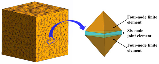
Figure 1.
Geometry of four-node finite elements and six-node joint elements.
According to Newton’s second law, the governing equation is given by the following [30]:
where M and C are the lumped mass and viscous damping matrix, respectively; x is the vectors of nodal displacements; and Fint, Fext, and Fc are the vectors of internal resisting forces, applied external forces, and contact forces.
The spatial hashing contact detection algorithm is employed to identify the pairs of mutually contacting discrete elements. Subsequently, repulsive forces are calculated using the distributed contact force penalty function method, and frictional forces are determined by applying the Coulomb friction law between all contacting pairs that overlap in the 3D space [31,32,33]. When the joint element is fractured, the crack element is formed in three modes: Mode I (tensile cracks), Mode II (shear cracks), and mixed Mode (mixed tensile-shear cracks), as shown in Figure 2. Typically, for quasi-static mechanical simulations of rocks under uniaxial or biaxial compression, the results obtained using displacement boundary conditions are generally consistent with the failure characteristics observed in laboratory experiments [34,35]. When the crack element is destroyed in Mode I, the normal stress (σn) and normal opening (O) should satisfy the following condition (Figure 2a):
where Op = 2hft/Pf is the normal opening when the normal stress (σn) equals the tensile strength (ft). h is the size of the elements, and Pf is the fracture penalty term. Or is the residual opening value when the normal stress (σn) equals to zero. f(D) is the heuristic function depicting the strain-softening behavior [36,37].
where a, b, and c are curve-fitting parameters with values of 0.63, 1.8, and 6.0, respectively, and D is the damage factor.
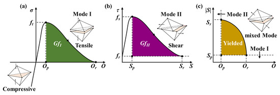
Figure 2.
Fracture modes of joint elements in the FDEM [28]. (a) Mode I (tensile cracks), (b) Mode II (shear cracks), and (c) mixed Mode (mixed tensile–shear cracks).
When the crack element is formed in Mode II, the relationship between the tangential stress (τ) and tangential slippage (S) can be expressed as follows (Figure 2b):
where Sp = 2hfs/Pf is the tangential slippage when the tangential stress (τ) equals the tangential strength (fs).
When the crack element is generated in mixed Mode, the following criterion should be met (Figure 2c):
3. Establishment of the 3D FDEM Model
In this paper, we focus on investigating the influence of confining pressure (CP) and thickness ratio (TR) on mechanical behaviors and failure patterns of CMS (SCS and MCM combinations), as displayed in Figure 3. The thickness ratio is defined as the thickness of the middle coal layer to the total sample thickness (50 mm), with the thicknesses of the roof and floor of the coal layer remaining equal (T1 = T3). The input parameters of the FDEM model were calibrated using laboratory tests (uniaxial compression and Brazilian splitting) on downhole core samples (sandstone, mudstone, and coal, coring depth > 2000 m) obtained from typical coal-measure strata in the Linxing–Shenfu gas field, Ordos Basin. The specimens for uniaxial compression and Brazilian splitting tests were prepared with dimensions of Φ25 mm × 50 mm and Φ25 mm × 13 mm, respectively. The experimental results indicate that sandstone possesses the highest uniaxial compressive strength (UCS), elastic modulus (E), and Brazilian tensile strength (BTS), followed by mudstone and coal, whereas Poisson’s ratio exhibits the opposite trend. The simulated results demonstrate that the mechanical responses and dominant failure modes of core samples derived from the calibrated FDEM model are in close agreement with those of laboratory experiments. Specifically, the relative errors of UCS, E, and BTS between FDEM simulations and laboratory measurements are less than 1.34%, 0.97%, and 2.62%, respectively. The finalized input parameters are presented in Table 1. The detailed calibration procedure and corresponding validation results can be found in our previously published work [28].
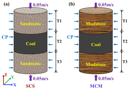
Figure 3.
The 3D FDEM model (T1 = T3, T1 + T2 + T3 = 50 mm). (a) SCS combination, (b) MCM combination.

Table 1.
Input parameters for the 3D FDEM model [28].
In this paper, the dimensions of the 3D FDEM model for the layered coal–rock combination are consistent with those of the rock specimens used in laboratory geomechanical tests (Φ25 mm × 50 mm). The normal element size is set to 1.25 mm, and axial loading rate is set to 0.1 m/s (with 0.05 m/s in the opposite direction) based on the analyses of element size sensitivity and loading rate sensitivity [28]. Moreover, the displacement boundary condition is applied in the axial direction while the confining pressure boundary condition is imposed in the radial direction. It should be noted that in CMS, the thicknesses of different lithological layers and the magnitudes of in situ stress at varying depths exhibit considerable variability (stress ratio (σV/σh) within the range of 0.8 to 2.0 across depths from 600 m to 2200 m). Considering both the computational efficiency of the 3D FDEM model and the research objectives of this paper, the thickness ratio is set within a range of 0.20–0.60, and the confining pressure is maintained at a relatively low level (0–4 MPa).
4. Numerical Results
4.1. Mechanical Properties
The stress–strain curves of layered coal–rock combinations under different thickness ratios and confining pressures are presented in Figure 4. Here, the peak stress refers to the initial peak axial stress. When the confining pressure is 0 MPa, both the SCS and MCM combinations exhibit the highest slopes in the pre-peak stages and maximum peak stresses at a thickness ratio of 0.20 (Figure 4a,b). As the thickness ratio increases, both the slope and peak stress of the stress–strain curve decrease gradually. In the post-peak stage, the axial stress drops sharply as the axial strain increases, indicating the approximately brittle failure characteristics. Under different confining pressures, the variation trends of the stress–strain curve slope and peak stress of the layered coal–rock combination with respect to the thickness ratio are consistent with those under unconfined pressures. As the confining pressure increases, the axial stress in the post-peak stage initially decreases and then fluctuates upward. This trend is particularly evident in the SCS combination (Figure 4c,e). In contrast, the post-peak behavior of the MCM combination shows a more distinct plateau, indicating a significant enhancement in ductility (Figure 4d,f).
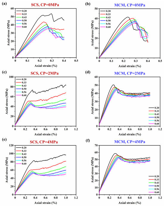
Figure 4.
Stress–strain curves of layered coal–rock combinations under different thickness ratios and confining pressures. (a) SCS combination under CP = 0 MPa, (b) MCM combination under CP = 0 MPa, (c) SCS combination under CP = 2 MPa, (d) MCM combination under CP = 2 MPa, (e) SCS combination under CP = 4 MPa, (f) MCM combination under CP = 4 MPa.
The confining pressure exerts a significant influence on the mechanical behaviors of layered coal–rock combinations, as exemplified by the cases with thickness ratios of 0.20 and 0.60 (Figure 5). The initial surge of axial stress in the stress–strain curve is attributed to the application of confining pressure. Notably, the linear elastic stages of stress–strain curves for layered coal–rock combinations under different confining pressures are nearly parallel, indicating that confining pressure has minimal effect on the elastic modulus in the FDEM simulation. This is consistent with previous findings obtained by the DEM regarding the mechanical properties of layered coal–rock combinations under confining pressure [38]. In contrast, the peak stress increases substantially with the growth of confining pressure. Overall, the higher the confining pressure, the more gradual the stress decline after reaching peak stress, which suggests the improved ductile behavior of the layered coal–rock combination.
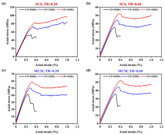
Figure 5.
Comparison in stress–strain curves of layered coal–rock combinations under different confining pressures. (a) SCS combination under TR = 0.20, (b) SCS combination under TR = 0.60, (c) MCM combination under TR = 0.20, (d) MCM combination under TR = 0.60.
The peak stresses of layered coal–rock combinations under different confining pressures are presented in Figure 6. It is evident that the confining pressure significantly enhances the peak strength of the layered coal–rock combination. Specifically, for the SCS composition with a thickness ratio of 0.20, the peak stress increases by 42.09% and 60.90% under confining pressures of 2 MPa and 4 MPa, respectively, compared to the unconfined condition (CP = 0 MPa). In contrast, the corresponding increments for the MCM composition are 21.54% and 40.86%, respectively. This phenomenon is associated with the mechanical strengths of the rock layers within the layered coal–rock combinations, suggesting that confining pressure exerts a more pronounced influence on the peak stress of the SCS composition. As the thickness ratio increases, the peak stress of the layered coal-rock combination gradually decreases, and the difference in peak stress between the SCS and MCM compositions gradually decreases. When the thickness ratio reaches 0.60, the peak stress of the layered coal–rock combination under the unconfined pressure approximates the UCS of the pure coal sample. In this case, the peak stresses of the SCS and MCM compositions under different confining pressures are close to each other.
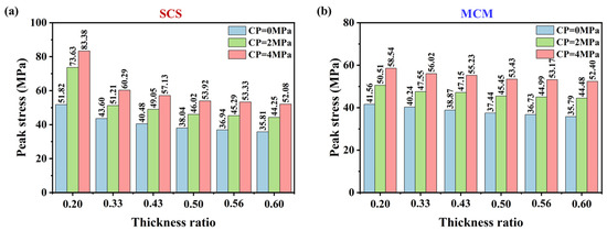
Figure 6.
Peak stress of the layered coal–rock combination under different confining pressures. (a) SCS combination, (b) MCM combination.
4.2. Failure Patterns
Figure 7 displays the failure patterns of the SCS combination under different thickness ratios and confining pressures. Under unconfined conditions, when the thickness ratio is 0.20, the coal layer exhibits shear-dominated failure, while the sandstone layer undergoes tensile-dominated failure. As the thickness ratio increases, the coal layer still experiences shear-dominated failure. Nevertheless, the sandstone layer remains undamaged when the thickness ratio exceeds 0.20 (Figure 7a).
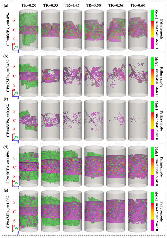
Figure 7.
Failure patterns of the SCS combination (ε represents the axial strain). (a) CP = 0 MPa, ε = 0.4%, (b) CP = 2 MPa, ε = 0.4%, (c) CP = 4 MPa, ε = 0.4%, (d) CP = 2 MPa, ε = 1.0%, (e) CP = 4 MPa, ε = 1.0%.
As the confining pressure increases, the number of shear and tensile cracks within the SCS combination gradually decreases under the same axial strain (Figure 7a–c). This is attributed to the fact that the confining pressure constrains radial deformation and enhances the mechanical strength of the SCS combination. When the axial strain reaches 1.0%, the primary failure mode of the coal layer remains consistent; however, the failure characteristics of the sandstone layer under confined conditions differ from those under unconfined conditions (Figure 7a,d,e). Specifically, at a thickness ratio of 0.20, the sandstone layer still exhibits tensile-dominated failure under confined conditions, but the number of failure cracks is significantly higher than that under unconfined conditions. Furthermore, under confined conditions, the tensile-dominated failure also occurs in the sandstone layer when the thickness ratio ranges from 0.20 to 0.50. In other words, the increase in confining pressure elevates the thickness ratio threshold of sandstone layer failure in the SCS combination.
In contrast, under unconfined conditions, the mudstone layer within the MCM combination can generate tensile-dominated cracks when the thickness ratio ranges from 0.20 to 0.60, although the number of such tensile cracks shows a decreasing trend (Figure 8a). At an axial strain of 0.4%, the total number of failure cracks gradually decreases as the confining pressure increases. When the thickness ratio reaches 0.60, no failure cracks are observed in the MCM combination under a confining pressure of 4 MPa (Figure 8c), which is attributed to the axial stress not having reached the peak stress of the MCM combination under this condition. Different from the SCS combination, the MCM combination shows a significant increase in the number of shear cracks within the mudstone layer under confined conditions; moreover, these shear cracks become dominant as the confining pressure increases (Figure 8d,e). In short, the differences in the failure modes of the layered coal–rock combinations are closely related to the mechanical properties of the individual layers and the stress states under different confining conditions.
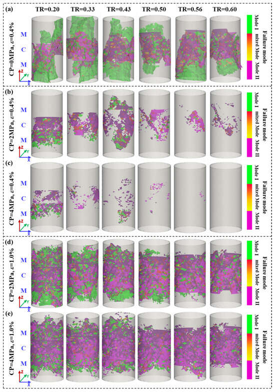
Figure 8.
Failure patterns of the MCM combination. (a) CP = 0 MPa, ε = 0.4%, (b) CP = 2 MPa, ε = 0.4%, (c) CP = 4 MPa, ε = 0.4%, (d) CP = 2 MPa, ε = 1.0%, (e) CP = 4 MPa, ε = 1.0%.
4.3. Stress Distributions
Stress distributions exert a significant influence on the ultimate failure patterns of the layered coal–rock combinations under different confining pressures. Here, the lateral stress distributions along the middle plane at an axial strain of 0.052% are shown in Figure 9 and Figure 10. It should be noted that negative values represent compressive stress while positive values indicate tensile stress.
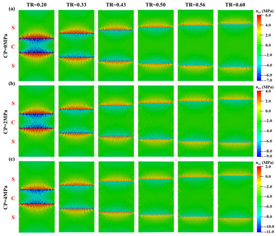
Figure 9.
Lateral stress distribution of the SCS combination at an axial strain of 0.052%. (a) CP = 0 MPa, (b) CP = 2 MPa, (c) CP = 4 MPa.
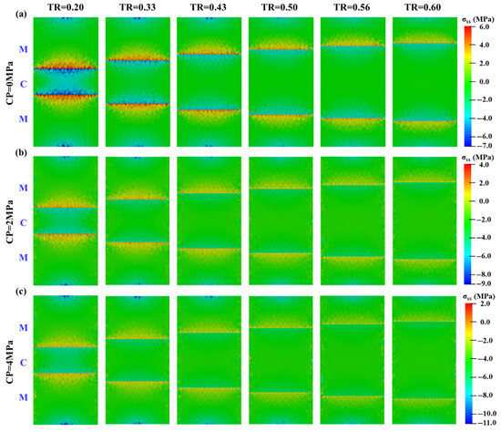
Figure 10.
Lateral stress distribution of the MCM combination at an axial strain of 0.052%. (a) CP = 0 MPa, (b) CP = 2 MPa, (c) CP = 4 MPa.
Notably, the lateral stress distribution within the layered coal–rock combination exhibits significant variations near the lithological interface, where a semi-elliptical (2D) or semi-ellipsoidal (3D) zone of lateral tensile/compressive stress is formed. Specifically, under unconfined conditions, a lateral compressive stress zone forms on the coal side of the interface, while a lateral tensile stress zone forms on the sandstone/mudstone side. This lateral tensile/compressive stress reaches its maximum at the lithological interface, defined as interfacial constraint stress in this paper. From the lithological interface toward the center of the rock/coal layer, the lateral tensile/compressive stress gradually diminishes. Furthermore, as the thickness ratio increases, the magnitudes of the corresponding lateral tensile/compressive stresses decrease (Figure 9a and Figure 10a).
Under confined conditions, the lateral stress distribution within the layered coal–rock combination exhibits a similar shape to that observed under unconfined conditions, although the magnitude of lateral tensile/compressive stress differs. As the confining pressure increases, the lateral compressive stress within the coal layer gradually increases, while the lateral tensile stress within the sandstone/mudstone layer gradually declines. This phenomenon arises from the superposition of confining pressure (compressive stress) and the inherent lateral stress within the combination.
Compared to the SCS combination, the MCM combination exhibits smaller magnitudes of lateral tensile/compressive stress under the same axial strain condition. At an axial strain of 0.052%, the typical lateral stresses along the central axis of the layered coal–rock combination are extracted under thickness ratios of 0.20 and 0.60, as shown in Figure 11. For the SCS combination with a thickness ratio of 0.20, it is evident that the lateral tensile stress decreases as the confining pressure increases. Conversely, the lateral compressive stress within the coal layer gradually increases (Figure 11a). In contrast, under the same confining pressure and axial strain, the MCM combination exhibits smaller lateral tensile/compressive stress. When the confining pressure reaches 4 MPa, there is no lateral tensile stress within the mudstone layer, resulting in a triaxial compressive stress state within the MCM combination (Figure 11c). Under the same strain conditions, the lateral tensile/compressive stress within the layered coal–rock combinations gradually diminish as the thickness ratio increases. For instance, when the thickness ratio reaches 0.60, the lateral compressive stress in the middle of the coal layer within the SCS combination approximates 0 MPa under unconfined condition (CP = 0 MPa); under a confining pressure of 4 MPa, the SCS combination enters a triaxial compressive state (Figure 11b). A similar phenomenon can also be observed in the MCM combination (Figure 11d).
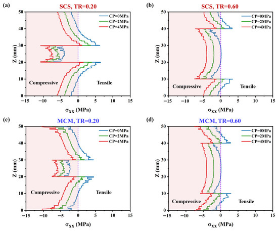
Figure 11.
Lateral stress of the layered coal–rock combination along the central axis at an axial strain of 0.052%. (a) SCS combination under TR = 0.20, (b) SCS combination under TR = 0.60, (c) MCM combination under TR = 0.20, (d) MCM combination under TR = 0.60.
Essentially, the lateral tensile/compressive stress in the layered coal–rock combination is closely related to the disparities in the mechanical properties of the different layers on both sides of the lithological interface, as well as the external loading conditions. Taking the layered cylinder sample composed of a sandstone/mudstone layer (higher elastic modulus and lower Poisson’s ratio) and a coal layer (lower elastic modulus and higher Poisson’s ratio) as an example, we assume that the layered sample is homogenous, isotropic, and linearly elastic, with no slippage at the lithological interface (Figure 12). When the layered sample is subjected only to σ1, the sandstone/mudstone layer exhibits a lower induced lateral strain due to the higher elastic modulus and lower Poisson’s ratio, while the coal layer shows the opposite behavior. To maintain consistent deformation at the lithological interface, a lateral tensile stress zone forms near the interface on the sandstone/mudstone layer side, while a lateral compressive stress zone forms on the coal layer side. When considering the effects of both axial stress (σ1) and confining pressure (σ2 = σ3) on the layered sample, stress superposition occurs between the confining pressure and the lateral tensile/compressive stress induced by σ1. This further increases the lateral compressive stress in the coal layer and reduces the lateral tensile stress in the sandstone/mudstone layer.
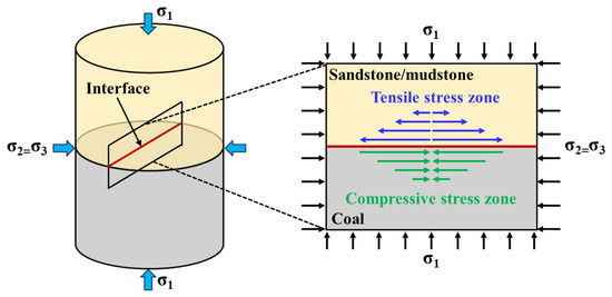
Figure 12.
Stress state of the layered sample under the axial stress and confining pressure.
According to the stress decomposition and deformation coordination principle at the lithological interface [39], the interfacial constraint stress can be calculated under confining pressure:
where the σIR and σIC are the interfacial constraint stress on the rock (sandstone/mudstone) layer side and coal layer side, respectively. λ, λ1, λ2, and λ3 are the coefficients related to mechanical properties.
where δ = ER/EC, η = μR/μC. ER and EC are elastic modulus of the sandstone/mudstone layer and coal layer, respectively. μR and μC are Poisson’s ratio of the sandstone/mudstone layer and coal layer, respectively.
From the above Equations (5)–(7), it is evident that the interfacial constraint stress is closely related to the differences in elastic modulus and Poisson’s ratio between adjacent layers, as well as the external loading conditions. Specifically, the greater the differences in elastic modulus and Poisson’s ratio between the adjacent layers and the higher the axial stress, the greater the interfacial constraint stress. Consequently, under the same conditions, the interfacial constraint stress in the SCS combination is higher than that in the MCM combination.
Here, the interfacial constraint stresses (at the top and bottom interfaces) along the central axis of the SCS/MCM combination at an axial strain of 0.052% are extracted and compared with the analytical solution, as illustrated in Figure 13. It can be observed that the interfacial constraint stress obtained from the FDEM simulation align well with the analytical solution across different thickness ratios, which further confirms the accuracy of the FDEM simulation. It should be noted that the inherent discreteness of the interfacial constraint stress obtained from the FDEM simulation, as well as its deviation from the analytical solution, are related to the tetrahedral element topology and distribution characteristics of the layered coal–rock combination model.
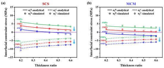
Figure 13.
Comparation in interfacial constraint stress of the layered coal–rock combination at the axial strain of 0.052%. (a) SCS combination, (b) MCM combination.
5. Discussion
In this paper, the mechanical properties, failure patterns, and stress evolution of layered coal–rock combinations are investigated by the 3D FDEM under different thickness ratios and confining pressures. Since the FDEM integrates the advantages of the finite element method (FEM) and discrete element method (DEM), it exhibits distinct superiority in addressing quasi-static simulation problems, such as accurately capturing the stress fields and explicitly characterizing the fracture types. Therefore, the FDEM has been widely adopted in rock mechanics, tunnel excavation, and hydraulic fracturing [25,40,41]. The 3D FDEM has also yielded excellent results in investigations into the effects of different combination types and interfacial properties on the mechanical responses and failure characteristics of layered coal–rock combinations [28,29]. This study further confirms that the 3D FDEM also performs exceptionally well in simulating mechanical behaviors of layered coal–rock combinations under confining pressure conditions. This provides an effective numerical simulation approach for addressing mechanical simulation problems in the field of rock engineering. However, the computational efficiency of the FDEM remains challenging when dealing with 3D simulations. At present, it is still rare to implement this method for mechanical simulations and hydraulic–mechanical coupling simulations under 3D conditions [42]. This also constitutes a key reason for conducting 3D laboratory-scale simulations and adopting the homogenization assumption in this study.
In underground engineering, the effects of the size effect and heterogeneity on rock mechanical properties cannot be ignored. The results of 3D uniaxial compression FDEM simulations of layered coal–rock combinations show that with the increase in sample size (from 25 mm to 50 mm in diameter), the elastic modulus (E) of the layered coal–rock combinations remains unchanged while the uniaxial compressive strength (UCS) decreases [28], which may be related to the fact that larger-sized rocks contain more discontinuities [43]. On the whole, the stress distribution and fracture characteristics of layered coal–rock combinations are similar across different rock sample sizes [28]. In addition, the influence of heterogeneity can be characterized by the cementation strength and inclination angle of the coal–rock interface. As the inclination angle increases, the lateral tensile/compressive stress gradually decreases, and the interfacial-dominated failure becomes more prominent. The UCS and E of layered coal–rock combinations exhibit a V-shaped variation trend of first decreasing and then increasing with an increase in the interface inclination angle (0–90°). As interfacial strength decreases, the UCS of layered coal–rock combinations decline progressively, and the UCS variation trend with an inclination angle shift from V-shaped to U-shaped [29]. Although the aforementioned investigations were conducted under uniaxial compression conditions, they provide an important reference for an in-depth understanding of the mechanical responses and fracture mechanisms of layered coal–rock combinations under confining pressure conditions. Further details regarding these findings are available in our prior works [28,29].
In fact, the stress state near the lithological interface is a key factor controlling the failure modes of layered coal–rock combinations. When the lateral tensile stress generated in the sandstone/mudstone layers of the layered coal–rock combination exceeds their tensile strength and Mode I fracture energy, it induces tensile-dominated failure in these layers. In contrast, the lateral compressive stress in the coal layers of the layered coal–rock combination causes the coal layers to be in a triaxial compressive state, leading to shear-dominated failure. As the coal layer thickness increases, the proportion of low-strength components (coal) in the layered coal–rock combination rises, resulting in a reduction in the overall mechanical properties. Simultaneously, the induced interfacial tensile stress gradually diminishes, which leads to a reduction in the number of tensile cracks in the sandstone/mudstone layer of the layered coal–rock combination. Furthermore, confining pressure has a significant impact on the mechanical behavior of layered coal–rock combinations. On one hand, it restricts the radial deformation of the combination, thereby enhancing the mechanical strength. On the other hand, the existence of confining pressure makes the lateral tensile stress and compressive stress at the interface become unequal, resulting in the layered coal–rock combination being in a state of triaxial compressive stress. This constitutes a key reason for the increased proportion of shear cracks in the coal and mudstone layers within layered coal–rock combinations.
When considering hydraulic fracturing stimulation of CMS, the high lateral compressive stress inside the soft coal layer leads to high resistance to fracture propagation, making it prone to generating short and wide fractures. Therefore, during coal layer hydraulic fracturing, the net pressure inside the fractures should be increased to promote the extension of fractures. Moreover, hydraulic fractures tend to propagate from layers with high elastic modulus to layers with low elastic modulus [44,45]. Once a hydraulic fracture penetrates the interface and enters a layer with low elastic modulus, the additional lateral compressive stress will prevent further extension of the hydraulic fracture. For CMS where both the coal layer and rock layer are relatively thick, the interior of the rock/coal layer is barely affected by the interfacial constraint stress, and the use of separate-layer hydraulic fracturing can fully stimulate the formation. For CMS where both the coal layer and rock layer have moderate thickness with little difference, the interior of the rock/coal layer is slightly affected by the interfacial constraint stress, and good stimulation effects can be achieved by adopting integrated cross-layer hydraulic fracturing and perforation within the rock layer. For the ultra-thin coal layer, the lateral compressive stresses formed by the upper and lower interfaces of the coal layer superimpose each other to form a strong stress shielding layer, which will hinder the cross-layer propagation of hydraulic fractures. In this case, separate-layer hydraulic fracturing technology should be considered. In short, the rock type, layer thickness, and stress distribution determine the selection of fracturing technology and pumping parameters in CMS, which is critical for achieving a larger stimulated reservoir volume (SRV) or a better pressure relief effect when stimulating the sandstone/mudstone/coal layers.
6. Conclusions
In this paper, a 3D FDEM model of typical lithological combination within the CMS is established. The mechanical properties, failure patterns, and stress distributions of sandstone–coal–sandstone (SCS) and mudstone–coal–mudstone (MCM) combinations are investigated under different confining pressures (CPs) and thickness ratios (TRs). On this basis, the failure mechanism of layered coal–rock combinations were analyzed. The following conclusions can be drawn:
- (1)
- With the thickness ratio increases, the proportion of the low-strength coal layer in the layered coal–rock combination rises, leading to a gradual decrease in the overall peak stress and elastic modulus, which eventually approach those of pure coal. Under the same thickness ratio, the peak stress and elastic modulus of the SCS combination are higher than that of the MCM combination.
- (2)
- Confining pressure restricts the radial deformation of layered coal–rock combinations and enhances their mechanical strengths (peak stress and elastic modulus). As confining pressure increases, the peak stress of layered coal–rock combinations gradually rises, and the plastic behaviors become increasingly prominent. Compared to the unconfined condition, the peak stress of the SCS combination (TR = 0.20) increased by 42.09% and 60.90% under confining pressures of 2 MPa and 4 MPa, respectively. In contrast, the corresponding increments for the MCM composition are 21.54% and 40.86%, respectively.
- (3)
- Under different thickness ratios and confining pressures, the coal layer in the combinations primarily develops shear-dominated cracks, whereas the sandstone layer mainly generates tensile-dominated cracks. Moreover, an increase in confining pressure elevates the critical thickness ratio for sandstone layer failure in the SCS combination, shifting it from 0.2 to 0.5. Accordingly, as the confining pressure rises (0–4 MPa), the failure mode of the mudstone layer in the MCM combination transitions from tensile-dominated to shear-dominated.
- (4)
- The stress distribution within the layered coal–rock combination is the key factor controlling its failure mode. The mechanical contrast between coal layer and rock layer induces interfacial constraint stress near the lithological interface. Under uniaxial compression, lateral compressive stress develops on the soft coal side, while lateral tensile stress forms on the hard rock side, which fundamentally explains why shear-dominated cracks occur in the coal layer and tensile-dominated cracks in the rock layer under such conditions. The presence of confining pressure increases the lateral compressive stress within the coal layer and reduces the lateral tensile stress in the rock layer, leading to a marked increase in shear cracks in the coal layer and a corresponding decrease in tensile cracks in the rock layer under confined conditions.
Author Contributions
Methodology, S.C.; Validation, Y.F.; Investigation, S.C. and X.S.; Data curation, P.L.; Writing—original draft, R.C.; Writing—review & editing, R.C.; Visualization, X.S.; Supervision, P.L.; Funding acquisition, Y.F. All authors have read and agreed to the published version of the manuscript.
Funding
The work is funded by the National Key Research and Development Program of China (No. 2023YFC2907502).
Institutional Review Board Statement
Not applicable.
Informed Consent Statement
Not applicable.
Data Availability Statement
The original contributions presented in this study are included in the article. Further inquiries can be directed to the corresponding author.
Conflicts of Interest
All authors were employed by the Coal Mining Research Institute, China Coal Technology and Engineering Group Co., Ltd., and State Key Laboratory of Intelligent Coal Mining and Strata Control. The authors declare that they have no known competing financial interests or personal relationships that could have appeared to influence the work reported in this paper.
References
- Li, L.; Ma, S.; Liu, X.; Liu, J.; Lu, Y.; Zhao, P.; Kassabi, N.; Hamdi, E.; Elsworth, D. Coal measure gas resources matter in China: Review, challenges, and perspective. Phys. Fluids 2024, 36, 071301. [Google Scholar] [CrossRef]
- Liu, D.; Zhao, Z.; Cai, Y.; Xu, S.; Qiu, F.; Sun, F. Review on Deep Coal Measure Gas Accumulation and Its Geological Effects of Efficient Coproduction. Energy Fuels 2025, 39, 14437–14454. [Google Scholar] [CrossRef]
- Meng, Z.; Shi, X.; Li, G. Deformation, failure and permeability of coal-bearing strata during longwall mining. Eng. Geol. 2016, 208, 69–80. [Google Scholar] [CrossRef]
- Xie, W.; Gan, H.; Chen, C.; Vandeginste, V.; Chen, S.; Wang, M.; Wang, J.; Yu, Z. A model for superimposed coalbed methane, shale gas and tight sandstone reservoirs, Taiyuan Formation, Yushe-Wuxiang Block, eastern Qinshui Basin. Sci. Rep. 2022, 12, 11455. [Google Scholar] [CrossRef]
- Liang, W.; Wang, J.; Leung, C.; Goh, S.; Sang, S. Opportunities and challenges for gas coproduction from coal measure gas reservoirs with coal-shale-tight sandstone layers: A review. Deep Undergr. Sci. Eng. 2025, 4, 83–104. [Google Scholar] [CrossRef]
- Bourne, S.J. Contrast of elastic properties between rock layers as a mechanism for the initiation and orientation of tensile failure under uniform remote compression. J. Geophys. Res. Solid Earth 2003, 108, 2395. [Google Scholar] [CrossRef]
- Zhao, Z.; Wang, W.; Wang, L.; Dai, C. Compression–shear strength criterion of coal–rock combination model considering interface effect. Tunn. Undergr. Space Technol. 2015, 47, 193–199. [Google Scholar] [CrossRef]
- Liu, J.; Wang, E.; Song, D.; Wang, S.; Niu, Y. Effect of rock strength on failure mode and mechanical behavior of composite samples. Arab. J. Geosci. 2015, 8, 4527–4539. [Google Scholar] [CrossRef]
- Chen, Y.; Zuo, J.; Liu, D.; Wang, Z. Deformation failure characteristics of coal–rock combined body under uniaxial compression: Experimental and numerical investigations. Bull. Eng. Geol. Environ. 2019, 78, 3449–3464. [Google Scholar] [CrossRef]
- Jing, S.; Wen, Z.; Jiang, Y.; Wen, J.; Du, W. Mechanical behaviors and failure characteristics of coal-rock combination under quasi-static and dynamic disturbance loading: A case based on a new equipment. Geomech. Geophys. Geo-Energy Geo-Resour. 2024, 10, 2. [Google Scholar] [CrossRef]
- Yin, D.; Chen, S.; Liu, X.; Ma, H. Effect of joint angle in coal on failure mechanical behaviour of roof rock–coal combined body. Q. J. Eng. Geol. Hydrogeol. 2018, 51, 202–209. [Google Scholar] [CrossRef]
- Zhang, H.; Elsworth, D.; Wan, Z. Failure response of composite rock-coal samples. Geomech. Geophys. Geo-Energy Geo-Resour. 2018, 4, 175–192. [Google Scholar] [CrossRef]
- Ma, Q.; Tan, Y.; Liu, X.; Gu, Q.; Li, X. Effect of coal thicknesses on energy evolution characteristics of roof rock-coal-floor rock sandwich composite structure and its damage constitutive model. Compos. Part B Eng. 2020, 198, 108086. [Google Scholar] [CrossRef]
- Zhang, H.; Lu, C.-P.; Liu, B.; Liu, Y.; Zhang, N.; Wang, H.-Y. Numerical investigation on crack development and energy evolution of stressed coal-rock combination. Int. J. Rock Mech. Min. Sci. 2020, 133, 104417. [Google Scholar] [CrossRef]
- Xie, X.; Liu, H.; Fang, X.; Yang, J.; Liu, J.; Liang, M.; Wu, G. Deformation Mechanism and Control Technology of Surrounding Rock of Three-Soft Coal Roadways under High Horizontal Stress. Energies 2023, 16, 728. [Google Scholar] [CrossRef]
- Chen, D.; Yuan, Y.; Ma, L. Deformation and failure characteristics and control technology of surrounding rocks in deep high-horizontal stress rock roadways in the Wanbei mining area. Front. Earth Sci. 2022, 10, 886221. [Google Scholar] [CrossRef]
- Yu, W.; Wang, W.; Chen, X.; Du, S. Field investigations of high stress soft surrounding rocks and deformation control. J. Rock Mech. Geotech. Eng. 2015, 7, 421–433. [Google Scholar] [CrossRef]
- Tian, Y.; Shu, X.; Tian, H.; He, L.; Jin, Y.; Huang, M. Effect of horizontal stress on the mesoscopic deformation and failure mechanism of layered surrounding rock masses in tunnels. Eng. Fail. Anal. 2023, 148, 107226. [Google Scholar] [CrossRef]
- Hou, B.; Zhang, R.; Zeng, Y.; Fu, W.; Muhadasi, Y.; Chen, M. Analysis of hydraulic fracture initiation and propagation in deep shale formation with high horizontal stress difference. J. Pet. Sci. Eng. 2018, 170, 231–243. [Google Scholar] [CrossRef]
- Zhang, Y.; Zhang, J.; Yuan, B.; Yin, S. In-situ stresses controlling hydraulic fracture propagation and fracture breakdown pressure. J. Pet. Sci. Eng. 2018, 164, 164–173. [Google Scholar] [CrossRef]
- Munjiza, A.; Owen, D.; Bicanic, N. A combined finite-discrete element method in transient dynamics of fracturing solids. Eng. Comput. 1995, 12, 145–174. [Google Scholar] [CrossRef]
- Ma, G.; Zhou, W.; Regueiro, R.A.; Wang, Q.; Chang, X. Modeling the fragmentation of rock grains using computed tomography and combined FDEM. Powder Technol. 2017, 308, 388–397. [Google Scholar] [CrossRef]
- Hu, L.; Wang, F.; Jiang, F.; Huang, G. Study on the influence of mineral composition on the mechanical properties of granite based on FDEM-GBM method. Simul. Model. Pract. Theory 2023, 129, 102834. [Google Scholar] [CrossRef]
- Vazaios, I.; Vlachopoulos, N.; Diederichs, M.S. Assessing fracturing mechanisms and evolution of excavation damaged zone of tunnels in interlocked rock masses at high stresses using a finite-discrete element approach. J. Rock Mech. Geotech. Eng. 2019, 11, 701–722. [Google Scholar] [CrossRef]
- Deng, P.; Liu, Q.; Huang, X.; Pan, Y.; Wu, J. FDEM numerical modeling of failure mechanisms of anisotropic rock masses around deep tunnels. Comput. Geotech. 2022, 142, 104535. [Google Scholar] [CrossRef]
- Sharafisafa, M.; Sato, A.; Sainoki, A.; Shen, L.; Aliabadian, Z. Combined finite-discrete element modelling of hydraulic fracturing in deep geologically complex reservoirs. Int. J. Rock Mech. Min. Sci. 2023, 167, 105406. [Google Scholar] [CrossRef]
- Wang, M.; Gan, Q.; Wang, T.; Ma, Y.; Yan, C.; Benson, P.; Wang, X.; Elsworth, D. Propagation and complex morphology of hydraulic fractures in lamellar shales based on finite-discrete element modeling. Geomech. Geophys. Geo-Energy Geo-Resour. 2024, 10, 71. [Google Scholar] [CrossRef]
- Cong, R.; Yang, R.; Gong, Y.; Li, G.; Huang, Z.; Zhang, B. Numerical investigation of mechanical responses and failure features of coal measure strata using combined finite-discrete element method. Comput. Geotech. 2024, 171, 106346. [Google Scholar] [CrossRef]
- Cong, R.; Yang, R.; Liu, Y.; Li, G.; Huang, Z.; Zhang, B. Influence of Interfacial Properties on Mechanical Behaviors and Failure Patterns of Coal–Measure Thin Interbedded Rocks Under Uniaxial Compression Using 3D FDEM. Rock Mech. Rock Eng. 2025, 58, 3589–3610. [Google Scholar] [CrossRef]
- Lisjak, A.; Mahabadi, O.; He, L.; Tatone, B.; Kaifosh, P.; Haque, S.; Grasselli, G. Acceleration of a 2D/3D finite-discrete element code for geomechanical simulations using General Purpose GPU computing. Comput. Geotech. 2018, 100, 84–96. [Google Scholar] [CrossRef]
- Munjiza, A.; Andrews, K. Penalty function method for combined finite–discrete element systems comprising large number of separate bodies. Int. J. Numer. Methods Eng. 2000, 49, 1377–1396. [Google Scholar] [CrossRef]
- Mahabadi, O.K.; Lisjak, A.; Munjiza, A.; Grasselli, G. Y-Geo: New combined finite-discrete element numerical code for geomechanical applications. Int. J. Geomech. 2012, 12, 676–688. [Google Scholar] [CrossRef]
- Smoljanović, H.; Živaljić, N.; Nikolić, Ž.; Munjiza, A. Numerical analysis of 3D dry-stone masonry structures by combined finite-discrete element method. Int. J. Solids Struct. 2018, 136–137, 150–167. [Google Scholar] [CrossRef]
- Xu, C.; Liu, Q.; Xie, W.; Wang, Y.; Li, S.; Lu, W.; Zhang, H. Investigation on artificial boundary problem in the combined finite-discrete element method (FDEM). Comput. Geotech. 2022, 151, 104969. [Google Scholar] [CrossRef]
- Deng, P.; Liu, Q.; Huang, X.; Bo, Y.; Liu, Q.; Li, W. Sensitivity analysis of fracture energies for the combined finite-discrete element method (FDEM). Eng. Fract. Mech. 2021, 251, 107793. [Google Scholar] [CrossRef]
- Munjiza, A.; Smoljanović, H.; Živaljić, N.; Mihanovic, A.; Divić, V.; Uzelac, I.; Nikolić, Ž.; Balić, I.; Trogrlić, B. Structural applications of the combined finite–discrete element method. Comput. Part. Mech. 2020, 7, 1029–1046. [Google Scholar] [CrossRef]
- Evans, R.H.; Marathe, M.S. Microcracking and stress-strain curves for concrete in tension. Matériaux Constr. 1968, 1, 61–64. [Google Scholar] [CrossRef]
- Wang, K.; Zhang, X.; Du, F.; Li, K.N.; Sun, J.Z.; Wang, Y.Q. Numerical study on damage response and failure mechanism of gas-containing coal-rock combination under confining pressure effect. Fuel 2023, 349, 128683. [Google Scholar] [CrossRef]
- Zhao, Z.; Wang, W.; Dai, C.; Yan, J. Failure characteristics of three-body model composed of rock and coal with different strength and stiffness. Trans. Nonferrous Met. Soc. China 2014, 24, 1538–1546. [Google Scholar] [CrossRef]
- Wang, W.; Ren, J.; Ding, Z.; Liu, Q. Failure mechanisms and stability control principles of high geostressed deep mining structures: Investigation by FDEM and field measurements. Eng. Fail. Anal. 2025, 169, 109233. [Google Scholar] [CrossRef]
- Yang, R.; Wu, X.-G.; Long, T.-D.; Li, G.-S.; Huang, Z.-W.; Xie, Z.-X.; Li, X.-X.; Wang, X.-Y. FDEM modeling of the fracture propagation behavior under the joint interaction of shale anisotropy and multi-lithologic stack. Pet. Sci. 2025, 22, 4656–4681. [Google Scholar] [CrossRef]
- Du, C.; Liu, Q.; Lei, Y.; Liu, H.; Lu, Y.; Jiang, H.; Xiang, S.; Yang, Y. Study the anisotropic behavior of layered surrounding rock based on 3D FDEM method. Tunn. Undergr. Space Technol. 2024, 146, 105644. [Google Scholar] [CrossRef]
- Sinha, S.; Walton, G.; Chaurasia, A.; Diederichs, M.; Batchler, T. Evaluating size effects for a porous, weak, homogeneous limestone. Rock Mech. Rock Eng. 2023, 56, 3755–3772. [Google Scholar] [CrossRef]
- Gu, H.; Siebrits, E. Effect of formation modulus contrast on hydraulic fracture height containment. SPE Prod. Oper. 2008, 23, 170–176. [Google Scholar] [CrossRef]
- Khanna, A.; Kotousov, A. Controlling the height of multiple hydraulic fractures in layered media. SPE J. 2016, 21, 256–263. [Google Scholar] [CrossRef]


Disclaimer/Publisher’s Note: The statements, opinions and data contained in all publications are solely those of the individual author(s) and contributor(s) and not of MDPI and/or the editor(s). MDPI and/or the editor(s) disclaim responsibility for any injury to people or property resulting from any ideas, methods, instructions or products referred to in the content. |
© 2026 by the authors. Licensee MDPI, Basel, Switzerland. This article is an open access article distributed under the terms and conditions of the Creative Commons Attribution (CC BY) license.