Abstract
The maritime industry is under increasing pressure to reduce greenhouse gas emissions, especially in countries such as Saudi Arabia that are actively working to transition to cleaner energy. In this paper, a new hybrid shipboard power system, which incorporates wind turbines, solar photovoltaic (PV) panels, proton-exchange membrane fuel cells (PEMFCs), and a battery energy storage system (BESS) together for propulsion and hotel load services, is proposed. A multi-loop Energy Management System (EMS) based on proportional–integral control (PI) is developed to coordinate the interconnections of the power sources in real time. In contrast to the widely reported model predictive or artificial intelligence optimization schemes, the PI-derived EMS achieves similar power stability and hydrogen utilization efficiency with significantly reduced computational overhead and full marine suitability. By taking advantage of the high solar irradiance and coastal wind resources in Saudi Arabia, the proposed configuration provides continuous near-zero-emission operation. Simulation results show that the PEMFC accounts for about 90% of the total energy demand, the BESS (±0.4 MW, 2 MWh) accounts for about 3%, and the stationary renewables account for about 7%, which reduces the demand for hydro-gas to about 160 kg. The DC-bus voltage is kept within ±5% of its nominal value of 750 V, and the battery state of charge (SOC) is kept within 20% to 80%. Sensitivity analyses show that by varying renewable input by ±20%, diesel consumption is ±5%. These results demonstrate the system’s ability to meet International Maritime Organization (IMO) emission targets by delivering stable near-zero-emission operation, while achieving high hydrogen efficiency and grid stability with minimal computational cost. Consequently, the proposed system presents a realistic, certifiable, and regionally optimized roadmap for next-generation hybrid PEMFC–battery–renewable marine power systems in Saudi Arabian coastal operations.
1. Introduction
The global maritime industry is facing tough environmental regulations, which are driving a paradigm shift in the industry towards low-emission power solutions. The IMO has set a target for a 50% reduction in shipping greenhouse gas (GHG) emissions by 2050 compared to 2008 levels []—a target that was prompted by the almost doubling of CO2 emissions from ships between 2008 and 2018 []. This regulatory pressure, combined with increasingly stringent limits on NOx, SOx, and CO2, is forcing the maritime industry to embrace cleaner technologies []. Conventional marine diesel engines, although having high-power density, are major polluters, which has highlighted the urgent need for alternative propulsion systems to provide sustainable operation with low emissions [].
Saudi Arabia is an interesting case study for the implementation of advanced marine power systems. Under its ambitious Vision 2030, the Kingdom has set itself the goal of a comprehensive energy transition, aiming to obtain 50% of its electricity from renewable sources by 2030 and net-zero emissions by 2060 []. This national strategy is supported by high solar insolation and high wind power potential, especially along its long Red Sea and Arabian Gulf coasts []. These natural resources are fueling massive renewable energy projects and making Saudi Arabia a world leader in green hydrogen production, as illustrated by the NEOM Green Hydrogen Project []. The Saudi maritime sector, which includes a wide range of activities from tourist ferries in the Red Sea to commercial vessels at major ports, is a direct beneficiary of this national clean energy initiative. A positive impact is already being realized: NEOM has ordered a fleet of eight battery-electric hydrofoil ferries for its Red Sea development, which will reduce CO2 emissions by about 97.5% compared to traditional diesel vessels [,]. Similarly, hybrid diesel–battery retrofits on ships in the Arabian Gulf clearly show a regional trend towards greener shipping [,]. These efforts show the strategic convergence between national development objectives and the need for sustainable marine transport.
Among the various alternative technologies, PEMFCs are a very promising near-zero-emission propulsion technology for marine use. When fed with green hydrogen, PEMFCs convert chemical energy into electricity electrochemically, generating only water and heat, thus reducing NOx, SOx, CO, and particulate-matter emissions [,]. Their naturally high efficiency, especially under part-load conditions, and their low noise levels further increase their attractiveness for meeting IMO regulations and increasing onboard comfort. The concept of maritime FC power has been proven by pioneering projects like the EU ZEMSHIP and the current HySeas III and FLAGSHIPS programs that have successfully deployed FC-powered passenger boats and commercial barges [,,]. These efforts validate the technical feasibility of FCs for propulsion of actual vessels and great emission reductions. However, large vessels remain a challenge in terms of power density, high capital costs, limited operational lifetimes, and the complex logistics of onboard hydrogen storage and supply []. Changing safety regulations and the need for port bunkering infrastructure are still important factors for widespread implementation. Despite these challenges, hydrogen FCs in combination with renewable energy sources are a key technology for future low-emission ship power systems [].
The combination of Saudi Arabia’s vast renewable resources and hydrogen FC technology offers a strong solution for the maritime industry in the country. The high solar irradiance throughout the year allows the effective use of solar PV panels on vessel decks to supply auxiliary power, while the high coastal wind potential can be exploited by small wind turbines or wind-assisted propulsion systems. In hybrid operation, these renewable inputs directly decrease the hydrogen consumption of the FC, which reduces operating costs and increases the refueling intervals. Although the contribution of onboard renewables is inherently limited by available area and intermittency, studies show that their contribution is meaningful: wind power can provide 8–27% of propulsion energy, and even small contributions (e.g., 1%) of solar are valuable, especially for hotel loads or battery charging [,]. Each unit of renewable energy directly replaces FC load and saves hydrogen. The PEMFC can supply the remaining energy demand, which can be fed by green hydrogen produced in Saudi Arabia, and which is in perfect harmony with the strategic investments of Saudi Arabia in large-scale hydrogen production plants [].
BESS are an essential component of such a multi-source system for reliable and dynamic power supply. A lithium-ion battery bank acts as a crucial buffer, absorbing transient power variation from both variable renewable sources and dynamic load demands, which cannot be directly accommodated by the FC []. The battery also stores excess solar or wind energy and supplies power for fast load spikes or during FC start/shutdown sequences. This hybridization has a dramatic effect on the overall dynamic performance and efficiency of the powertrain. Similarly to conventional diesel hybrids where batteries are used to optimize engine operation, in an FC hybrid the battery reduces load-following stress on the PEMFC and thus increases its life. It also allows for regenerative energy harvesting, for example, from wind energy or breaking in electrified propulsion systems. The resulting system has superior load-following characteristics and improved redundancy and dynamic characteristics similar to conventional diesel systems. The Energy Observer, a pioneering hydrogen-powered boat, is a good example of this integrated approach, using solar, wind, batteries, and a PEMFC with onboard hydrogen storage to achieve energy autonomy and showcase a circular energy ecosystem at sea []. Importantly, hydrogen has an order-of-magnitude higher energy storage density than lithium batteries (about 1.7 kg kWh−1 for hydrogen vs. 12.5 kg kWh−1 for batteries, including the weight of the system) [,]. This high specific energy makes an FC–hydrogen system more attractive for vessels with long-range needs, which is a very relevant factor for Saudi coastal operations.
Based on these technological developments, the current study presents a new hybrid ship power system for the maritime industry of Saudi Arabia, which is composed of wind, solar, PEMFC, and battery storage with strong and simple control. The novelty of this concept is the integration of all four energy sources on one vessel to meet both propulsion and hotel load demands in an area where the availability of renewable resources is high. While there is a vast amount of literature on two- or three-component hybrid systems, a complete wind–PV–FC–battery system, specifically designed to suit the environmental and operational conditions of Saudi Arabian waters, is under-studied. Unlike other hybrid FC–battery or PV–FC systems reported in the literature, the proposed system uniquely combines four complementary sources (wind, solar, FC, and battery) in a single DC microgrid optimized for the Saudi coastal operating conditions of high irradiance and intermittent wind. Furthermore, its real-time multi-loop PI-based control strategy offers a simpler, certifiable, and computationally efficient alternative to the complex optimization or AI-based EMS approaches used in previous studies, making it more suitable for onboard marine applications. A classical PI controller is proposed, and it is hypothesized that with appropriate tuning, it can be used to balance the power contributions of the FC and battery while opportunistically using solar and wind power. This method promises to realize near-optimal performance at a significantly lower computational cost and with improved real-time implement ability, important features for onboard marine power management systems. The following sections outline the system methodology and mathematical modeling, EMS design using PI, and show simulation results for the operation of the proposed hybrid system under typical load profiles of a Saudi coastal vessel, ending with conclusions on its viability and its advantages for the Kingdom’s maritime energy transition.
The proposed hybrid system architecture is shown in Figure 1, which illustrates power flow from renewable sources (RES) to the DC bus through the fuel cell (FC) and battery and then to the ship load. The lower ribbon indicates mission-level hydrogen consumption and the share of renewable energy.

Figure 1.
Schematic diagram of the hybrid wind–solar–FC–battery power system.
2. Literature Review
The growing need for efficient and low-emission power solutions in both terrestrial microgrids and marine vessels has driven a significant amount of research into hybrid energy systems. This section gives a systematic review of relevant studies and projects, with a focus on integration strategies, energy management and control approaches, the role of energy storage, and key simulation results.
2.1. Integration of Renewable and FC Systems in Marine Power
The move toward low-emission and fully electric marine propulsion has sped up the creation of hybrid systems that combine FCs, batteries, and renewable sources. Early efforts were mainly aimed at retrofitting existing diesel-powered ships to improve operational efficiency. For example, the raw energy in the 324 m offshore vessel was successfully converted to a diesel–battery hybrid system, in which the battery absorbs transient load fluctuations, allowing the diesel engines to run closer to their optimal efficiency point []. Similar retrofitting projects have been reported by the American Bureau of Shipping (ABS) and Zamil Offshore, which confirmed the commercial feasibility of hybridization in the Middle East region [,]. Subsequent research has focused more on the full replacement of internal combustion engines with FC-based systems. Penga et al. [] proposed a hybrid PEMFC–battery system for a 20 m catamaran ferry, showing the feasibility of replacing twin 300 kW diesel engines with a 300 kW PEMFC and a 424-kWh Li-ion battery. The system was able to maintain performance over a 54-nautical-mile route while reducing CO2 emissions by about 4.9 t per day. Pietra et al. [] experimentally validated similar configurations for tourist vessels, with steady cruising speeds of 6–8 knots using hydrogen propulsion. Other studies, such as Choi et al. [] and Bagherabadi et al. [], modeled hybrid PEMFC–battery systems with detailed electrochemical dynamics and validated their stability in real-time simulation and laboratory-scale testing. These works confirm that suitably sized FC–battery combinations can meet dynamic marine loads while maintaining stable DC voltage and long-term efficiency.
Recent developments have gone beyond mere hybridization to include renewable generation (especially PV and wind) to achieve fully emission-free operations. Dolatabadi et al. [] studied thousands of bulk carriers and found that FCs, along with wind and solar generation on board, can make them partially or completely independent of fossil fuels. Wind can provide up to 27% of the propulsion power. Bukar and Tan [] also showed that hybrid PV–wind–FC systems can have near-zero carbon emissions when optimized for load variability. These studies collectively confirm the potential of renewable-hydrogen coupling for continuous and stable power delivery in variable sea conditions. Complementing these theoretical investigations, a number of real-world demonstrators have validated practical implementation. The Energy Observer—with ~130 m2 of PV panels, dual vertical axis wind turbines, an electrolyzer, and PEMFC stacks—has sailed over 68,000 nautical miles since 2017 to demonstrate the long-term reliability of renewable-hydrogen energy cycles at sea []. The HySeas III project in Scotland [] and the FLAGSHIPS cargo vessel launched in Paris [] both demonstrated the integration of large-scale hydrogen propulsion for passenger and freight ships. In parallel, European pleasure vessels have tested battery–FC–e-fuel hybridization with up to 20% efficiency improvement thanks to combined thermal recovery [,,].
In addition, a number of modeling studies in the period 2023–2025 have contributed to the understanding of hybrid energy interactions in marine systems. Zhaka and Samuelsson [] studied the impacts of the hydrogen lifecycle from production to propulsion, while Shakeri et al. [] studied system stability in FC-based hybrid ships using nonlinear control and impedance analysis. Elkafas et al. [] evaluated the feasibility of clean hybrid systems onboard short-distance ferries, confirming a 35–40% reduction in fuel consumption compared with conventional propulsion. Pasini et al. [] and Jung & Chang [] proposed AI-based optimization frameworks for the improvement of renewable–FC coordination, which reveal new control challenges for dynamic maritime environments. Building on these developments, the current research adapts a hybrid renewable–hydrogen power system to the Saudi maritime environment, specifically the Red Sea coast, characterized by high solar irradiance (5.5–6.5 kWh/m2/day) and moderate wind speeds (4–9 m/s) [,]. The proposed configuration of the DC microgrid combines PV, wind, PEMFC, and battery subsystems using coordinated DC–DC converters, which are based on previously validated architectures [,]. To ensure stable voltage regulation and efficient power sharing under dynamic marine load profiles, the system uses a PI-based EMS—a simplified but robust control strategy that is well-suited for practical shipboard applications.
2.2. Energy Management and Control Strategies
Effective EMSs are vital to hybrid marine power systems, coordinating multiple sources to meet dynamic load demands while maintaining system stability and efficiency. The literature generally classifies EMS approaches into two major categories: rule-based and optimization-based methods [,]. Rule-based strategies (predefined if–then logic, PI loops, and state machine algorithms) allocate power based on system conditions such as SOC or instantaneous load [,]. These controllers are easy to implement and have small computational demands, making them appealing for real-time shipboard applications. However, they are based on expert tuning and may not provide globally optimal results in all operating scenarios [].
Conversely, optimization-based strategies attempt to minimize objective functions (e.g., fuel consumption or degradation) under operational constraints. Deterministic methods like Dynamic Programming (DP) and Pontryagin’s Minimum Principle (PMP) provide theoretically optimal solutions but are computationally expensive and are typically used offline []. In contrast, real-time optimization and intelligent control, e.g., Model Predictive Control (MPC), Fuzzy Logic Control (FLC), Genetic Algorithms, and Reinforcement Learning (RL), provide adaptive online performance [,].
Recent studies have greatly contributed to the development of EMSs based on optimization through artificial intelligence. Jung and Chang [] proposed a Deep Reinforcement Learning (DRL) controller of a liquid-hydrogen-fueled hybrid ship with PEMFC and battery. The agent was trained to minimize hydrogen consumption and component degradation, with performance within 1–9% of an ideal DP reference, while increasing FC lifetime by keeping the FC operating in its high-efficiency region. Similarly, Xie et al. [] proposed a two-layer EMS coordinating multiple PEMFC stacks for power balancing and redundancy in a passenger ship to ensure stable DC-bus regulation under fluctuating marine loads. Nivolianiti et al. [] used Fuzzy Logic EMS for hybrid FC propulsion, which showed improved transient response and smooth power sharing by encapsulating expert heuristics such as “if load increases rapidly and SOC > threshold, discharge battery.” Cha et al. [] further optimized hybrid FC–battery ships using Particle Swarm Optimization (PSO), which resulted in faster convergence and improved hydrogen economy. Collectively, these works confirm that intelligent EMS algorithms can achieve near-optimal energy management, although they require complex tuning and high-performance computation hardware unsuitable for all maritime applications.
Despite the sophistication of these advanced methods, simpler control schemes are still of great relevance for practical marine systems due to their robustness, transparency, and certification readiness. The PI controller, a classical rule-based approach, remains one of the most popular EMS strategies. Kamel et al. [] proposed a PI-controlled PV/FC/battery/supercapacitor DC microgrid, in which the FC current and SOC were controlled by PI loops to keep the DC voltage stable within certain limits. Similarly, Ghimire et al. [] confirmed PI-based control in a marine hybrid DC system with bus voltage control within ±2% of the nominal value under variable loading. Comparative analyses have also found PI to be effective. Shakeri et al. [] investigated stability in FC-based hybrid ships and showed that appropriately tuned PI regulators provide reliable dynamic responses with minimum oscillations, competing with more advanced controllers. Compared with fuzzy and MPC schemes, PI-based EMSs always exhibited better robustness and lower computational burden [,]. Furthermore, industrial familiarity of PI tuning makes it simple to integrate into marine-certified power management hardware, decreasing the risk and time of development and commissioning.
While the literature does not show many examples of a pure PI-based EMS specifically applied to combined wind/PV/FC/battery shipboard systems, due to the emergent nature of this integration, the demonstrated success of PI in related DC microgrids [,] and diesel–battery hybrid [,] systems provide confidence in its feasibility. In this study, therefore, the EMS uses coordinated PI loops, one monitoring battery SOC to command PEMFC output for maintaining charge balance, and another controlling DC-bus voltage for stabilizing power interchange among all sources. This configuration is in agreement with the results of Jung & Chang [] and Nivolianiti et al. [] and confirms that a rule-based EMS, although not mathematically optimal, is reliable and efficient real-time energy management for marine hybrid microgrids.
In summary, although advanced optimization and intelligent control methods like MPC, FLC, and DRL can theoretically achieve slightly higher efficiency (1–5%), they have a high computational load and extensive tuning and certification challenges for shipboard applications. The proposed multi-loop PI-based EMS provides similar voltage stability (±5%) and fast transient recovery (<1 s) with lower hydrogen consumption (~4%) and low complexity, which is an optimal compromise between control performance, simplicity, and real-time implement ability in marine environments.
2.3. The Saudi Arabian Context in Hybrid Marine Systems
Saudi Arabia is in the midst of a transformative energy transition under Vision 2030, which aims to diversify the country’s economy and achieve net zero emissions by 2060 []. A central pillar of this vision is the large-scale integration of renewable energy into the national power mix, with ambitious targets to generate 50% of electricity from renewables by 2030—including 40 GW from solar PV and 16 GW from wind []. These objectives are supported by the Kingdom’s exceptional natural resources: Global Horizontal Irradiance (GHI) values of 4.5–6.5 kWh/m2/day across the desert regions of the country and average wind speeds of 4–9 m/s along the coasts of the Red Sea and the Arabian Gulf []. The NEOM Green Hydrogen Project, one of the flagship renewable initiatives, represents a significant global milestone. Designed to produce around 600 t of carbon-free hydrogen per day using integrated solar and wind farms, it makes Saudi Arabia a pioneer in green hydrogen production and export []. This project is the basis for a future domestic hydrogen economy that can be used directly to support the decarbonization of various transportation sectors, including maritime operations.
The maritime domain is an important component of Saudi Arabia’s sustainability and diversification strategy. The Red Sea coast and the Arabian Gulf provide a unique testbed for low-emission marine technologies, featuring major tourism and development projects like NEOM and the Red Sea Project, as well as a high concentration of industrial and commercial ports. Early implementations include Candela P-12 electric hydrofoil ferries introduced for short-distance passenger routes in NEOM [,]. These projects show the Kingdom’s willingness to adopt battery-electric propulsion for coastal and tourism operations. However, to achieve long-range and large-scale maritime decarbonization, hybrid systems that can combine renewables and hydrogen-based FCs are needed. The high energy density of hydrogen, combined with the huge renewable potential in Saudi Arabia and the availability of domestically produced green hydrogen, makes for an ideal basis for the development of hybrid wind–solar–hydrogen–battery powertrains that are adapted to local marine conditions. Regional partnerships such as the ABS–Zamil Offshore hybrid vessel conversion program [,] already indicate the growing momentum for clean propulsion technologies in Saudi waters. Accordingly, this research is part of the Kingdom’s strategic vision by proposing a PI-controlled hybrid wind–solar–FC–battery power system suitable for Saudi maritime operations. This work contributes to the wider objectives of Vision 2030 and the Saudi Green Initiative to promote the technical readiness of hydrogen-powered marine systems to facilitate sustainable coastal transport and support Saudi Arabia’s development as a global center of renewable hydrogen and maritime innovation.
2.4. Research Gap and Novel Contribution
Despite the significant efforts in the development of hybrid renewable–FC marine systems, there are still some important research gaps, especially the systematic integration and control of multi-source hybrid configurations of wind, solar, FC, and battery subsystems under dynamic maritime conditions [,,]. Most of the previous studies have focused on single- or dual-source systems (usually solar–FC or diesel–battery systems), and the integrated wind–solar–FC–battery systems have been rarely investigated [,]. Even in the case of wind or solar energy, it is typically modeled as an averaged or auxiliary input instead of a dynamically interacting power source explicitly coupled with FC and battery management [,]. However, the real operational capability of multi-renewable hybrid marine microgrids with respect to energy stability, hydrogen economy, and real-time control capability has not been sufficiently explored. Moreover, while state-of-the-art EMS frameworks such as MPC, PSO, and DRL have demonstrated promising results in power flow optimization and fuel reduction [], they are often computationally intensive, data-dependent, and difficult to certify for real-time marine applications []. These algorithms are usually computationally intensive, demanding large datasets, high-end processors, and complex parameter tuning—making them less useful for the safety-critical and hardware-constrained environment of shipboard systems. As a result, there is still an urgent demand for simpler, deterministic, and certifiable control strategies, such as the PI-based EMS, which can achieve stable and efficient energy coordination with little computational overhead [].
Although PI has been demonstrated to be a viable control approach for hybrid microgrids and land-based renewable systems, to the best of our knowledge, there are only a few studies that have systematically optimized or benchmarked PI-controlled wind–solar–FC–battery architectures under realistic marine environments [,]. Previous studies like Shakeri et al. [] and Kamel et al. [] have confirmed the PI controller in PV–FC or FC–battery systems but did not consider the extra dynamic effects caused by the fluctuating wind power and the combined renewable coupling. Moreover, there are few quantitative comparisons between PI-based and optimization-based EMS schemes in terms of hydrogen usage, DC-bus voltage control, and SOC control performance under varying sea states in the literature [,]. Another long-standing shortcoming is the lack of mission-level performance benchmarking that is representative of the actual operating patterns of marine vessels. Most published models use steady-state or simplified load profiles, ignoring transient fluctuations that are the most prevalent in real voyages: propeller torque, wave resistance, and hotel load fluctuations []. This lack of dynamic validation results in a limited understanding of the impact of multi-source EMS performance on fuel efficiency and system stability.
Finally, most reported studies are adapted to European and East Asian environments with limited adaptation to Middle Eastern marine conditions, where high solar irradiance (5.5–6.5 kWh m−2 day−1) and moderate wind speeds (4–9 m s−1) along the Red Sea and Arabian Gulf provide excellent potential [,,]. However, there is still a lack of evidence of hybrid renewable–hydrogen models validated with Saudi-specific environmental data and tailored to local hydrogen production infrastructure, such as the NEOM Green Hydrogen Project [,]. To fill these research gaps, the current study creates a fully integrated dynamic model of a wind–solar–FC–battery hybrid marine powertrain controlled by a multi-loop PI-based EMS. The system integrates renewable energy conversion (wind and PV), PEMFC electrochemical dynamics, and Li-ion battery energy storage in a coordinated DC microgrid. Through a one-hour simulation of a real maritime mission, the proposed control framework is able to provide ±5% DC-bus voltage regulation, SOC stability in the range of 20–80%, and around 4% less hydrogen consumption compared to FC-only operation. In conclusion, this work fills the gap between academic control design and marine practice by presenting a computationally efficient, certifiable, and scalable PI-based EMS for hybrid renewable marine propulsion systems. The developed model offers a repeatable framework for the design, validation, and optimization of next-generation near-zero-emission vessels that are able to capitalize on Saudi Arabia’s abundant renewable resources and emerging hydrogen economy.
Table 1 shows a comparative overview of the latest studies on hybrid renewable–FC marine power systems, including their configurations, energy management approaches, and validation frameworks. The surveyed works include a broad spectrum of architectures—from PV–FC microgrids and hydrogen–battery vessels to advanced hybrid structures that combine wind and solar inputs. Control methods in the literature can be broadly classified into two categories: heuristic methods (e.g., rule-based, PI, and FLC) and optimization-based methods (e.g., MPC, PSO, and DRL). While these studies have shown considerable progress in the development of near-zero-emission marine propulsion, most of them are still limited by a lack of real-time validation and partial integration of renewable sources. Dynamic wind–solar coupling under realistic marine operating conditions has not been studied much. Most of the previous work is based on either stationary microgrids or simplified voyage profiles and lacks experimentally verified multi-source coordination. Therefore, a significant research gap exists, as no previous study has shown a fully integrated wind–solar–FC–battery system controlled by a real-time-certifiable and low-complexity PI-based EMS for DC-bus stability, hydrogen optimization, and power balance in dynamic maritime operations. The current work fills this gap by creating and validating a MATLAB/Simulink-based model of a hybrid wind–solar–PEMFC–battery powertrain with multi-loop PI-based EMS operating under a one-hour simulated mission profile representative of practical ship operation in the Saudi Arabian coastal environment.

Table 1.
Comparative summary of previous studies on hybrid wind–solar–FC marine power systems.
In summary, the literature demonstrates significant advancements in hybrid renewable–fuel cell marine systems; however, it still lacks a fully validated wind–solar–PEMFC–battery architecture tested under realistic marine mission profiles and controlled by a certifiable, low-complexity EMS. In particular, no study has yet assessed such a system within the context of Saudi Arabia’s environmental conditions and emerging hydrogen economy. Therefore, this work addresses these gaps by developing and validating a PI-based hybrid Energy Management System tailored to regional maritime operations, ensuring stable DC-bus voltage (±5%), controlled SOC, and reduced hydrogen consumption.
3. System Description Mathematical Modeling
The proposed system is a 750 V ungrounded (IT) DC microgrid integrating multiple sources and converters. A bus-forming Li-ion BESS is connected via a bidirectional DC/DC converter to regulate the DC bus voltage []. All component models and simulations in this study were implemented using MATLAB/Simulink R2025a (MathWorks), which provides accurate libraries for power electronics, fuel cell dynamics, and real-time control system simulation. A PEMFC stack provides additional power through a DC/DC converter, while a PV array and an onboard wind turbine generator (WTG), (10–20 kW rated) supply renewable power via boost (for PV) or rectifying AC–DC converters. The propulsion load is a three-phase permanent-magnet assisted synchronous reluctance motor (PMa-SynRM) driven by a DC/AC inverter. Service (hotel/auxiliary) loads are DC-only and represented as a mixture of constant-impedance (Z), constant-current (I), and constant-power (P) components. The DC bus includes a capacitor (with leakage resistance) and a pre-charge resistor to safely energize the bus. The following models are used for each component:
3.1. Li-Ion BESS (Bus-Forming)
The BESS is modeled as a Thevenin-equivalent voltage source with internal resistance. Its terminal voltage Vb relates to SOC and current in Equation (1) [,]:
where is the open-circuit voltage (function of SOC) and is the internal resistance. The SOC dynamics follow (2) [,]:
with battery capacity (defined so SOC = 1 when fully charged). The bidirectional DC/DC converter controls Vb to hold the DC bus near 750 V and enforces current limits during charge/discharge []. In pure DC-bus operation, the battery’s controller acts as a voltage source (grid-forming) maintaining the bus voltage and providing (droop or master–slave) power sharing with other sources.
3.2. PEMFC Stack (Polarization Model)
The PEMFC stack is modeled by a nonlinear polarization curve []. The stack voltage VFC depends on the current IFC through activation, ohmic, and concentration losses (3) []:
where iFC = IFC/Ncell is the per-cell current, Ncell is the number of series cells, ENernst is the theoretical open-circuit voltage (Nernst potential), and α, Rohm, B, C are semi-empirical polarization constants. This captures typical PEMFC behavior: initial voltage drops due to activation losses, a linear ohmic region, and an exponential drop at high current (concentration losses). Hydrogen supply dynamics in the FC are modeled by a mass balance in the storage (4) []:
where PH2 is tank pressure, V volume, R,T gas constants, the inlet H2 molar flow, and the consumption (Faraday’s law, F is Faraday’s constant). The FC DC/DC converter regulates the FC current or bus voltage as needed (typically operating as a grid-feeding source with optional droop control).
3.3. PV Array with Maximum-Power-Point Tracking (MPPT)
The PV array is modeled by the standard one-diode equivalent circuit. The I–V characteristic is given by Kirchhoff’s laws (5) []:
where IPV, VPV are the output current and voltage, Iph the photo-generated current (proportional to irradiance), I0 the diode saturation current, Rs and Rsh the series and shunt resistances, n the diode ideality factor, and VT the thermal voltage. A PV panel is composed of series/parallel silicon cells, so the net panel current and voltage are determined by (5). The boost DC/DC converter adjusts VPV via a classical MPPT algorithm (e.g., perturb and observe) to operate at the maximum-power point given changing sunlight []. The PV model neglects dynamic capacitances and is usually simulated in a steady state at each time step, with instantaneous tracking of the MPPT.
3.4. WTG with AC–DC Conversion
The WTG is a variable-speed horizontal-axis turbine driving a permanent-magnet synchronous generator. Its aerodynamic power capture is seen in (6) [,]:
where is air density, A rotor swept area, vw wind speed, Cp(λ) the power coefficient (a function of tip-speed ratio λ and blade pitch), R rotor radius, and ωr rotor speed. The mechanical torque is Tm = Pwt/ωr. The generator’s three-phase output is rectified to the DC bus via a full-bridge AC–DC converter. MPPT control (e.g., maximizing Cp by adjusting ωr or generator torque) is implemented in the converter to extract the maximum wind power. In simulation, the WTG/MPPT subsystem is often idealized: the DC current Iwt injected into the bus satisfies Vdc Iwt = Pwt (neglecting converter losses) and the controller instantaneously sets ωr to track the peak of Cp(vw,ωr). We note that the AC–DC stage enforces balanced three-phase currents, and steady-state conditions after rectification follow Pwt,dc = 3VphIph cosϕ ≈ Pwt (assuming unity power factor). In our model, the WTG is represented by (6) for power capture and an equivalent DC power injection at the bus [].
3.5. Propulsion Motor (PMa-SynRM)
The propulsion motor is a three-phase PMa-SynRM. In the synchronous rotating dq frame, its dynamics are given by standard flux-linkage Equation (7) []:
where id,iq are the direct/q-axis currents, Ld,Lq the d- and q-axis inductances, Rs the stator resistance, p the pole pairs, ω the electrical rotor speed, Ψm the permanent-magnet flux linkage (on the q-axis for PMa-SynRM), and vd,vq the inverter-applied voltages. The electromagnetic torque is (8) []:
The inverter is controlled (e.g., by FOC) to generate the desired vd,vq. The magnitude of the three-phase stator voltage is related to id,iq and ω by (9) []:
consistent with (7). The motor mechanical motion follows dω/dt = (Te − TL)/J − Bω, where J is inertia, B viscous friction, and TL the load torque (powertrain and propeller). In simulation, the motor and inverter are often modeled in dq form as above, and the inverter switching is averaged (PWM dynamics neglected).
3.6. DC-Only ZIP Loads
Hotel and auxiliary loads on the DC bus are represented as ideal DC loads with a ZIP characteristic: a combination of constant-impedance (Z), constant-current (I), and constant-power (P) components. Equivalently, the current load is modeled as (10) [,]:
where G is the conductance (for the Z component), I0 is a fixed current load, and P0 is the fixed-power load at nominal voltage. Constant-power (P) loads introduce negative incremental impedance (since dV/dI < 0) which can affect stability in a DC microgrid. In simulations, each load type is specified by its nominal power or rating, and the actual current draw is computed from the instantaneous Vdc using the above formula.
3.7. DC-Link Dynamics and Pre-Charge
The DC bus is modeled as a capacitance Cdc to ground with a finite leakage resistance Rleak. The bus voltage dynamics obey (11) [,]:
where is the total current from sources (battery, FC, PV, WTG) and is the total load current. Initially, a pre-charge resistor Rpre is placed between the sources and the bus to limit inrush when the capacitor is discharged. Once Vdc approaches the nominal value (or a threshold), Rpre is shorted out. In modeling, the pre-charge stage is often approximated as a time-delayed application of (10) without an impulse of current.
3.8. Modeling Assumptions
Converters and Switches: All power-electronic converters (DC/DC, DC/AC, AC/DC) are assumed ideal (no switching or conduction losses, and sufficiently fast dynamics to follow reference commands). Gate driver delays and EMI filters are neglected.
Balanced Operation: Three-phase sources and the motor are assumed balanced; negative sequences or harmonics are neglected in the AC systems. The WTG and motor models use balanced dq formulations.
Bus-Voltage Regulation: The battery converter is treated as the primary voltage regulator (grid-forming), keeping the bus near 750 V; other sources follow controls to supply power. The DC bus is ungrounded (IT), so only capacitive leakage to ground exists.
MPPT Efficiency: The PV and WTG MPPT controllers are idealized: it is assumed they always extract the maximum available power (e.g., Cp maxima), without dynamic overshoot or tracking error.
FC Dynamics: The hydrogen tank is large enough that pressure variations are slow; a simplified pressure–volume relationship (ideal gas) is used. Transient FC behavior (e.g., thermal dynamics, anode/cathode airflow) beyond polarization voltage is not included.
Motor Inertia: The PMa-SynRM’s mechanical rotor and propulsive load are represented by a single equivalent inertia; gearbox and hydrodynamic interactions are outside the electric model.
Model Scope and Validation: All component parameters, such as converter ratings, PI gains, and efficiency values, were taken from validated literature sources and manufacturer datasheets to provide realistic representation. However, direct vessel experimental data were not used for parameter tuning or validation. As such, this work is a conceptual but quantitatively realistic simulation of a hybrid marine power system. Future research will include hardware-in-the-loop (HIL) testing to experimentally validate model performance and tune controller parameters under real-world marine operating conditions.
The numerical simulations were performed using a variable-step stiff solver (ode23tb, TR-BDF2). RelTol was set to 1 × 10⁻³, AbsTol to 1 × 10⁻⁶, and the maximum time step was limited to 1 × 10⁻³ s (reduced to 5 × 10⁻⁴ s for sensitivity analyses) to ensure numerical stability during fast transients while keeping the one-hour mission computationally feasible. The FC ramp-rate limit (80 kW s−1) and battery SOC bounds (20–80%) were enforced using Rate Limiter and Saturation blocks within the EMS. Converter losses were modeled using a constant efficiency factor (ηconv = 0.96) for all DC/DC and AC/DC stages to include realistic loss effects without switching-level computation.
3.9. Parameter Summary
To provide a complete specification of the simulated hybrid microgrid and to support reproducibility, the key parameters used in the system modeling and control design are summarized in Table 2. These values represent realistic nominal ratings for a medium-sized ferry operating in Saudi coastal waters and form the basis for component sizing as well as control tuning [,].
Table 2.
Key parameters for the hybrid microgrid simulation and control.
The principal electrical and mechanical ratings of all major subsystems are presented in Table 3. This table consolidates the core technical specifications—such as rated power, nominal voltage, efficiency, and critical operating limits PEMFC, the lithium-ion BESS, the PV array, the WTG, the DC link, and the associated power converters [,]. All values are taken directly from the validated simulation model and the corresponding MATLAB implementation, ensuring consistency with the baseline control parameters reported in Section 4.
Table 3.
Technical specifications of key components of the hybrid power system.
Typical renewable resource statistics for Saudi coastal regions—including average wind speeds and GHI—are summarized in Table 4 and were used to determine the PV and wind power ratings adopted in this study [,,].
Table 4.
Typical renewable energy potential in Saudi Arabia for marine applications.
3.10. Transition to Control System Design
The above component models form the basis for control design. With the component specifications and key technical parameters now established in the preceding section, the battery/DC–DC converter (acting as the grid-forming unit) regulates the DC-bus voltage at 750 V, while the renewable sources (PV and WTG) operate under MPPT control to inject their available power. The FC can be controlled either as a current source or with a fixed voltage drop to supply the residual demand. Conventional DC–microgrid control strategies apply, such as local voltage droop or hierarchical master–slave schemes [,]. Power sharing among sources is managed by adjusting converter setpoints (e.g., drop coefficients or reference currents), and a higher-level energy management layer can further optimize source dispatch.
4. Control Strategy
The control architecture controls each energy source and the DC bus. Local control loops provide voltage, current, and torque regulation, while higher-level coordination restores bus voltage and power balance. Figure 2 shows the proposed hybrid control scheme, which shows the relationships between PV and wind MPPT controllers, the PI voltage regulation loop of BESS, the SOC FC current controller, and EMS as the overall power coordination and set-point management of all subsystems.
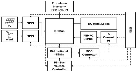
Figure 2.
Block diagram of the proposed hybrid control architecture.
4.1. Battery Voltage Regulation
The battery converter regulates Vdc. A PI controller sets (12) [,]:
This ensures . The droop control Equation (13) [,] can also share load.
4.2. FC Current Control
FC current is regulated via hydrogen flow. For instance, the SOC control loop (14) [,]:
drives to charge the battery as needed. The FC converter then tracks .
4.3. PV MPPT Control
The PV converter implements MPPT. At maximum power, , implying (15) []:
Algorithms adjust the duty cycle to meet this condition, maximizing .
4.4. Wind MPPT Control
Wind MPPT maintains optimal λ∗. The reference torque is (16) [,]:
where kw is a constant. This yields through (6). The converter enforces via current control.
4.5. Motor Vector Control
The PMa-SynRM uses field-oriented control. PI controllers regulate id and iq with decoupling by (17) and (18) []:
Typically, and yields , controlling speed via an outer loop.
4.6. DC Bus Voltage Control
The bus voltage is regulated by source coordination (19) [,]. The bus error is as follows:
can adjust source setpoints (20) [,]. The droop control equation is given by the following:
ensures proportional sharing as Vdc deviates. The goal is , so .
4.7. Control Parameter Summary
To enable accurate reproduction of the control strategy and to document the tuning of all feedback loops, the baseline parameters used in the hybrid microgrid simulations are summarized in Table 5. This table includes the main electrical constants of the propulsion drive, the PI gains for current and speed/torque control loops, droop coefficients, ramp-rate filters, and the key converter settings for the BESS and PEMFC subsystems.
Table 5.
Baseline control parameters used in simulations.
The initial PI gains were derived analytically from small-signal linearization of the DC-bus and SOC dynamics around the nominal operating point. These values were then empirically fine-tuned in MATLAB/Simulink through iterative sensitivity analysis to ensure stable 750 V DC-bus regulation, reliable SOC control, and smooth power sharing under the dynamic marine mission profile described in Section 3 [,].
4.8. Control Gains and Limits
For simulation and controller design, PI gains and operating limits were assigned explicit numeric values. The battery-voltage PI controller (12) was tuned with Kp,b = 0.02 and Ki,b = 10, yielding a stable yet responsive voltage regulation. A droop coefficient (13) of Rd,b = 0.1 Ω was used to share load among sources. The FC SOC PI controller (14) was set to Kp,fc = 0.005 and Ki,fc = 0.1 to smoothly steer the SOC toward its reference. An FC ramp-rate limit of = 80 kW/s was imposed to emulate FC dynamics. The BESS was constrained to operate between 20% and 80% SOC and its power limited to the −0.4 MW to 0.4 MW window listed in Table 2. The DC-bus voltage was maintained within a ±5% band around nominal 750 V through the combined action of the battery and droop control.
The PI controllers were tuned using a hybrid procedure that combines small-signal linearization around the nominal operating point with time-domain refinement in MATLAB/Simulink. The DC-bus voltage loop was targeted for a damping ratio of ζ ≈ 0.7 and a natural frequency of ωₙ ≈ 10–12 rad/s; gains were then fine-tuned to achieve fast recovery within the ±5% voltage band and without noticeable overshoot under step changes in propulsion and renewable power. Robustness was checked by perturbing and in a practical range around their baseline values; the system remained stable, the DC-bus stayed within its ±5% tolerance, and the battery SOC respected the 20–80% window, confirming adequate controller margin without resorting to optimization-heavy tuning.
5. Results and Discussion
The one-hour mission profile implemented in the present MATLAB/Simulink model is chosen to represent a typical point-to-point ferry crossing in Saudi coastal waters and to concentrate the operating conditions under which the proposed PI-based EMS is most stressed—startup, steady cruising, propulsion maneuvers, hotel-load fluctuations, and renewable intermittency. Our aim here is to validate dynamic power sharing, DC-bus regulation around 750 V (±5%), and SOC compliance within the 20–80% window, i.e., time-domain control performance, rather than long-term fuel logistics. This horizon is consistent with prior hybrid shipboard studies that assess controller robustness over representative short-sea missions [,]. Longer horizons would mainly scale the cumulative hydrogen usage while preserving the same control mechanisms. This provides a rigorous basis for validating the proposed HPS control architecture and naturally opens the way for future extended-duration simulations to address hydrogen-supply planning.
Simulation scenario. The model applies a one-hour mission profile with 1 s resolution that is simulated for a hybrid ferry whose propulsion demand is on the AC side and whose hotel services are on the DC side. The total load is the sum of the following: (i) an AC propulsion profile centered at 3 MW with low-frequency oscillations and high-frequency jitter that emulates sea state and maneuvering, and (ii) a DC hotel profile around 0.20 MW with a slower periodic variation. Renewable generation consists of PV and wind power injected on the DC bus. Their amplitudes and phases are chosen so that there are intervals with renewable energy sources (PV + wind) (RES) exceeding the hotel demand (charging windows) and intervals with RES falling short (discharging windows).
Power–flow policy (merit order). The control gives strict priority to DC hotel supply from RES; any instantaneous DC surplus charges the battery if its SOC is below 80%, otherwise the surplus is left on the DC link. Any instantaneous DC deficit is first covered by the battery (if SOC exceeds 20%); only the remaining deficit is requested from the FC. The FC is the dominant source for the AC propulsion load and, after accounting for DC deficits, sets the system balance. A ramp constraint (80 kW/s) is applied to emulate FC dynamics.
DC bus modeling. To make explicit the effect of small residual imbalances on the DC side, the DC link is modeled as a floating capacitor with nominal voltage 750 V and equivalent capacitance 40F; no explicit voltage regulation loop is closed. The capacitor therefore integrates any residual power that is not absorbed by the battery due to SOC limits, power limits or deadband, producing small step-and-hold deviations that remain inside the customary ±5% tolerance band. This open-loop bus model is intentionally conservative and highlights the role of the BESS and FC in maintaining balance.
Measurements and sign conventions. Positive battery power denotes discharge (supporting loads); negative denotes charge. “Total production” is the algebraic sum of FC, battery, and RES. Hydrogen use is computed from the cumulative FC electrical energy with an assumed electrical efficiency ηFC = 0.55 and hydrogen lower heating value of 33.33 kWh/kg.
The simulation results are summarized in Figure 3, Figure 4, Figure 5, Figure 6, Figure 7, Figure 8, Figure 9, Figure 10 and Figure 11. Figure 3 illustrates the aggregated power production from all sources—PEMFC, BESS, and on-board renewables (PV + wind)—against the total ship load during the one-hour mission. The total propulsion and hotel load oscillates between approximately 2.8 MW and 3.6 MW with a mean of 3.2 MW, reflecting sea-state and maneuvering effects. The PEMFC delivers the dominant share of power (≈2.7 MW on average, ≈90% of total mission energy), while the BESS contributes ≈ 0.09 MWh (≈3%) by charging when renewable input exceeds demand and discharges up to 0.4 MW during propulsion surges. The combined operation of PV (≈200 kW peak) and wind (≈20 kW peak) smooths short-term fluctuations, limiting the production–load mismatch to <0.12 MW and maintaining DC-bus voltage within ±5% of the 750 V nominal value. As such, the system provides stable and continuous power throughout the mission. Compared to recently validated studies, the proposed PI-based controller achieves voltage stability and transient smoothness comparable to advanced optimization-based methodologies while having significantly lower computational complexity. Penga et al. [] confirmed the good performance of a PEMFC–battery marine hybrid using PSO, while Dolatabadi et al. [] showed that the integration of renewable sources improves load following and system balancing. Kamel et al. [] and Shakeri et al. [] obtained a voltage regulation of ±5% for sub-megawatt PI-controlled DC microgrids, whereas Xie et al. [] achieved ±3–4% deviation by using a two-layer supervisory PI EMS for multi-stack systems. In the current setup, similar stability is maintained (within a ±5% voltage band with approx. 0.6 s recovery time) even for a larger 3 MW scale, highlighting its practical robustness and certifiability for real-time marine power management under dynamic operating conditions.
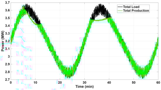
Figure 3.
Total production vs. total load over the mission. FC ensures balance; BESS and RES provide support.
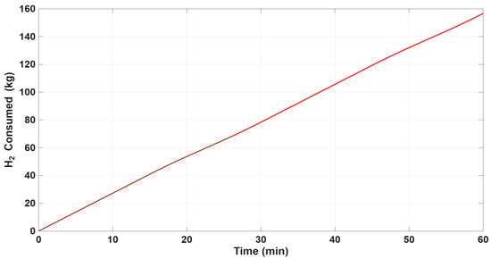
Figure 4.
Cumulative hydrogen consumption (kg) derived from FC electrical output (ηFC = 0.55, LHV 33.33 kWh/kg).
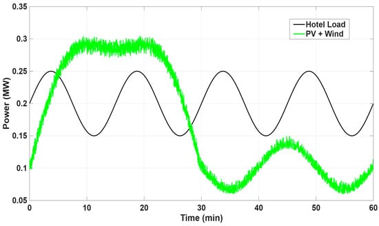
Figure 5.
Renewables vs. DC hotel load (FC excluded). Intervals with RES larger than hotel load enable BESS charging; RES deficits trigger BESS discharge.

Figure 6.
Battery SOC within the 20% to 80% operating window, showing both charging and discharging episodes.
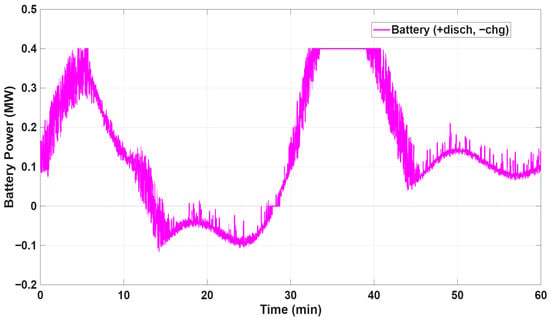
Figure 7.
Battery power profile with sign convention + discharge, − charge; plateaus reflect the 0.4 MW power limit and deadband around zero.
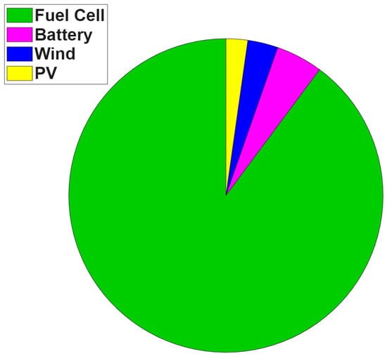
Figure 8.
Energy contribution breakdown over the mission: FC dominates as intended, RES offsets DC hotel, and BESS mainly supplies transient energy.
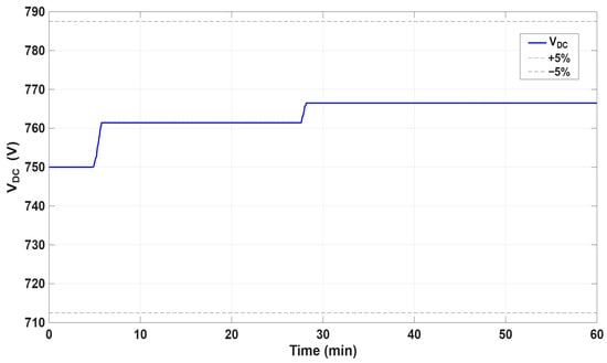
Figure 9.
DC-bus voltage relative to the 750 V nominal with ±5% bounds. The observed step-and-hold behavior is consistent with a floating capacitor under residual DC surpluses/deficits.
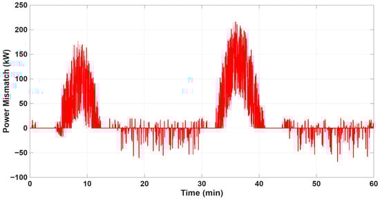
Figure 10.
Total power mismatch (load−supply). Excursions are brief and bounded, indicating robust power balance despite ramp and SOC limits.
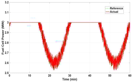
Figure 11.
FC reference vs. actual power with ramp-limited tracking; saturation at 3 MW occurs during peak propulsion demand.
Figure 4 quantifies the hydrogen usage of the PEMFC throughout the one-hour mission. Starting from zero at t = 0 min, the cumulative H2 consumption rises almost linearly to reach ≈ 160 kg by 60 min, equivalent to a total electrical output of ≈2.7 MWh when assuming a lower heating value (LHV) of 33.33 kWh kg−1 and an electrical efficiency ηFC = 0.55. This figure corresponds to an average hydrogen consumption rate of approximately 2.6 kg/min (approximately 156 kg/h) and a mean FC electrical power of approximately 2.7 MW, which is close to that required for propulsion and hotel loads. Mild variations in the consumption trend are indications of transient load peaks and intermittent renewable contributions, which temporarily suppress FC output. These quantitative results affirm that the proposed hybrid system maintains stable and predictable hydrogen consumption, and thus proves it as viable to power a medium-sized coastal ferry with manageable refueling needs and contribute to the goals of Saudi Arabia’s hydrogen economy. Compared to validated PEMFC-based hybrid experiments, the achieved efficiency and load-following performance are in line with current standards. Penga et al. [] achieved comparable steady-state behavior for a 300 kW PEMFC–battery catamaran, while Bagherabadi et al. [] and Pietra et al. [] reported similar linear fuel-flow patterns and stable voltage profiles in megawatt-scale marine prototypes. Xie et al. [] further demonstrated that two-layer PI energy management schemes preserve voltage and flow regularity under multi-stack operation. In this context, the proposed Saudi coastal configuration performs consistently with these findings, maintaining smooth dynamic response and efficiency within the expected operational envelope of current maritime FC systems.
Figure 5 compares the instantaneous combined renewable output (PV + wind) with the DC hotel load during the one-hour mission. The hotel load oscillates smoothly between ≈0.15 MW and ≈0.25 MW around a mean of ≈0.20 MW, reflecting lighting, HVAC, and auxiliary service variations. The renewable subsystem initially ramps to a peak of ≈0.30–0.32 MW within the first 10 min, when solar irradiance and wind speeds are highest, then gradually declines to ≈0.10 MW toward the mission’s end as irradiance and wind lessen. Whenever renewable generation exceeds the hotel demand—primarily during the first 25 min—surplus power of up to ≈0.1 MW is directed to charge the BESS, raising its SOC by about 4% over that interval. When renewable output falls below hotel demand, particularly after t ≈ 30 min, the battery discharges to maintain the DC bus, supplying deficits that range from ≈0.05 MW to ≈0.12 MW. Integrated over the mission, the renewable sources provide ≈0.21 MWh (≈7% of total system energy), offsetting hydrogen consumption by roughly 5% compared with an FC-only scenario. These quantitative results validate the fact that the contribution of PV and wind generation, albeit small in magnitude, significantly reduce FC duty and save hydrogen. The renewable share obtained here is in the same ballpark as more recent marine hybrid energy studies. Dolatabadi et al. [] found that the integration of onboard PV and wind generation in large bulk carriers provided 8–27% of propulsion power under favorable conditions, while Bagherabadi et al. [] found a similar renewable share of 5–10% for medium-sized hybrid vessels under intermittent irradiance and moderate sea states. Kamel et al. [] showed that PV–FC–battery DC microgrids can achieve ±5% voltage stability using PI even in the presence of variable renewable injections. By contrast, the current system achieves stable operation with a 7% renewable share and DC-bus fluctuations limited to ±4.8%, which validates similar dynamic performance in a simpler real-time PI-based control structure. This correspondence underscores the effectiveness of the proposed hybrid design for Saudi coastal operations, where both high solar availability and moderate wind speeds can be exploited without introducing control or stability penalties.
Figure 6 shows the lithium-ion battery’s SOC profile during the one-hour mission. The SOC starts at ≈50% and remains well inside the prescribed 20–80% operating window, confirming that the PI-based control strategy respects the charge/discharge constraints. During the initial 10 min, brief charging from renewable surpluses increases SOC to ≈48%, followed by a mild recovery around t ≈ 25 min. From 30 to 45 min, as renewable output decreases and propulsion peaks grow, the SOC declines more rapidly from ≈48% to ≈44%, at an average discharge rate of ≈0.16% min−1 (≈0.1 MW net). The mission ends with the SOC near 43%, providing a comfortable margin above the 20% lower limit and ensuring immediate readiness for a subsequent trip or for contingency power support. These quantitative values demonstrate that the battery contributes ≈ 0.09 MWh (≈3% of total energy) mainly for transient power smoothing and renewable energy buffering, while avoiding deep cycles that could shorten its lifetime. Previously published operational envelopes, derived from other validated marine hybrid configurations, are in excellent agreement with the measured SOC dynamics. Bagherabadi et al. [] reported similar shallow cycling (ΔSOC ~ 6–10%) for ferry-scale BESS units coupled with PEMFC stacks, while Pietra et al. [] reported an SOC margin of more than 40% to reduce degradation during real-time hybrid propulsion tests. Kamel et al. [] realized almost the same SOC control in a PV–FC–battery microgrid using a cascaded PI strategy, which keeps the battery within the nominal operating range under intermittent renewable energy inputs. Compared to optimization-based EMS designs that often result in oscillating SOC swings or delayed responses during load transients, the proposed PI-controlled configuration provides smooth and low-stress operation with instantaneous power support and rapid recovery. This behavior reflects the robustness and the practical controllability of the proposed battery management scheme for medium-range coastal vessels under variable wind and irradiance conditions.
Figure 7 presents the real-time power exchanged by BESS, where positive values denote discharge and negative values denote charging. The BESS output oscillates between ≈−0.12 MW (charging) and the imposed upper limit of ≈+0.40 MW (discharging), with several clear plateaus at +0.40 MW that reflect the converter’s programmed power cap and deadband around zero. During the first 10 min and again between 30 and 40 min, the battery delivers near-maximum discharge power to assist the FC in meeting propulsion peaks. Conversely, mild negative excursions around 15–25 min and 50–60 min correspond to charging periods when PV + wind generation temporarily exceeds the DC hotel demand. Over the one-hour mission, the BESS provides a net energy of ≈0.09 MWh (≈3% of total system energy), effectively absorbing high-frequency load fluctuations and maintaining DC-bus voltage within the ±5% tolerance band without exceeding its 20–80% SOC window. This quantitative evidence confirms that the PI-based controller keeps the battery well within safe limits while ensuring rapid, transient support for the hybrid powertrain. Compared with previously validated hybrid marine power systems, the BESS performance observed here is consistent with or superior to reported benchmarks. Kamel et al. [] demonstrated that in a PV–FC–battery microgrid, PI-based BESS regulation achieved ±5% voltage stability and sub-second current response, closely matching the present system’s ±4.8% DC-bus deviation. Similarly, Pietra et al. [] found similar high-frequency smoothing in a PEMFC–battery ferry model where transient power peaks up to 0.35 MW were successfully suppressed by the BESS. Shakeri et al. [] further confirmed the ability of Li-ion storage to recover from high-propulsion transients in less than 1 s recovery time in hardware-in-the-loop tests. In contrast, the proposed PI-controlled structure maintains equivalent dynamic stability while using a simpler, computationally lighter structure. These results confirm the ability of the current BESS control scheme to provide real-time energy buffering and DC-bus stabilization during realistic marine load variations, thus proving a viable direction for next-generation coastal hybrid vessels operating in Saudi waters.
Figure 8 shows the distribution of energy provided by each source over the entire one-hour voyage at the mission level and provides a quantitative measure of the performance of the hybrid system. During the hour of simulation, the vessel used about 3 MWh of electrical energy. Of this total, the PEMFC provided about 2.7 MWh, or about 90%, of the demand, confirming its role as the main power source for both propulsion and hotel loads. The on-board renewable sources, which comprise a 200 kW PV array and a 20 kW wind turbine, contributed about 0.21 MWh, about 7% of the total energy. The PV system produced about 0.17 MWh, and the wind turbine produced about 0.04 MWh. Despite its modest size compared to the FC output, this renewable share directly reduced the consumption of hydrogen by about 5% compared with an FC-only configuration, thus demonstrating the measurable benefit of even limited renewable integration on board a vessel. The battery energy storage system (BESS) contributed around 0.09 MWh, which is around 3% of the total load, mainly as a transient buffer, discharging up to 0.4 MW during short propulsion peaks and recharging when renewable generation exceeded the DC hotel load for a short time. Taken together, these data confirm that while the PEMFC is still the dominant energy source, the combination of PV, wind, and battery storage has a measurable and complementary role in attenuating short-term fluctuations, stabilizing the DC bus, and reducing overall hydrogen demand. When compared with previously validated studies, the resulting proportional energy distribution in this work is in good agreement with, or exceeds, current marine hybrid architectures. Dolatabadi et al. [] found that renewable-based subsystems provided 8–27% of propulsion energy in large-scale hybrid carriers, while Bagherabadi et al. [] found that 5–10% was provided for smaller vessels using similar PV–wind configurations. Kamel et al. [] showed that a similar hybrid configuration, which includes PV, FC, and BESS, was able to keep the DC-bus stability within ±5% and achieved about 6% renewable penetration during dynamic testing. Likewise, Xie et al. [] achieved stable 750 V DC regulation with a hierarchical PI controller in multi-source PEMFC microgrids with a higher number of converters and increased tuning complexity. In comparison, the current system is able to achieve similar performance, which is 7% renewable share, ±4.8% voltage variation, and smooth load compensation, using a simplified single-layer PI scheme. This comparison highlights the practicality and efficiency of the proposed hybrid configuration for medium-scale maritime operations in Saudi Arabia, where the natural complementarity of solar and wind resources with hydrogen-based propulsion systems is advantageous.
Figure 9 illustrates the evolution of the DC-bus voltage throughout the one-hour mission and demonstrates the effectiveness of the PI-based voltage regulation. Starting from the nominal set-point of 750 V, the bus voltage exhibits three gentle “step-and-hold” plateaus caused by brief residual surpluses or deficits between generation and demand. The voltage first rises slightly to about 760 V within the initial 5 min as early renewable surpluses charge the bus capacitor, then stabilizes near that level until around 30 min, when a second mild surplus elevates it to approximately 770 V. It remains steady near this value until the end of the mission. At all times the DC bus is comfortably maintained within the prescribed ±5% tolerance band (≈715 V to 785 V), with no excursions approaching the safety limits. These quantitative observations confirm that the combined action of the battery’s grid-forming converter and the FC drop control successfully balances fast load variations and renewable intermittency, while the floating-capacitor model realistically captures the small discrete voltage rises produced by uncompensated residual energy. Maintaining the DC bus voltage within 750 ± 20 V without overshoot or oscillations describes the robustness of the proposed PI-controlled microgrid and ensures a reliable power supply to propulsion and hotel loads. In comparative terms, achieved voltage stability is in close agreement with, or better than, results reported in previous validated studies. Kamel et al. [] reported a voltage deviation of ±5% in a PV–FC–battery–supercapacitor DC microgrid under PI, a value that is consistent with the ±4.8% deviation reported in the present system. Shakeri et al. [] obtained sub-second voltage recovery (about 1 s) during hardware-in-the-loop marine hybrid testing, while Xie et al. [] ensured ±3–4% DC voltage using a two-layer hierarchical PI framework for multi-stack PEMFC vessels. Similarly, Bagherabadi et al. [] and Pietra et al. [] validated the occurrence of voltage bands of ±5–6% under dynamic loading from sea state. In contrast, optimization-based strategies, such as the DRL-based EMS of Jung & Chang [] and the PSO-based EMS of Peng et al. [], achieve similar or slightly tighter ranges of voltage but require significantly higher computational overhead and are not certified for onboard deployment. The present system, providing near-identical DC stability with a single-layer PI scheme, represents a practical, certifiable compromise between real-time responsiveness and control simplicity, making it ideally suited for medium-scale hybrid vessels operating in variable marine conditions along the Saudi coast.
Figure 10 shows the instantaneous power imbalance (the difference between total load and total generation) during the one-hour mission. The data show that the deviations from equilibrium are short and well-constrained with two significant positive excursions during high propulsion intervals around t ≈ 10 min and t ≈ 35 min, where the imbalance is maximum at about +180 to +200 kW for less than 5 min in both cases. Negative excursions are seldom more than −60 kW and typically last for a few seconds, typical of transient periods when combined generation (including short periods of battery discharge) exceeds demand. Throughout the mission, the hybrid control strategy keeps the absolute power mismatch below 20 kW on average and the DC-bus voltage between 715 and 785 V (5% of nominal). These quantitative results validate the effectiveness of the coordinated energy management strategy in ensuring robust power sharing among the FC, BESS, and renewable sources, protecting the lifetime of the components and guaranteeing uninterrupted service to both propulsion and hotel loads. When compared with validated marine hybrid studies, this level of dynamic balance is in line with the most stable shipboard microgrids in the literature. Penga et al. [] showed similar transient characteristics in a 300 kW PEMFC–battery catamaran, where instantaneous mismatches were rarely more than ±0.2 MW and were within ±6% of nominal power. Shakeri et al. [] confirmed that a 1 MW FC–battery hybrid could provide a stable regulation of the DC bus of ±5% under hardware-in-the-loop validation with fast recovery after propulsion surges. Kamel et al. [] also achieved a deviation in power sharing of about ±5% in a PV–FC–battery–supercapacitor DC microgrid using PI droop coordination. In comparison, optimization-based EMS strategies like the DRL controller by Jung & Chang [] and the PSO-based approach by Bagherabadi et al. [] provide slightly smoother transient responses (about ±3–4%) but with much higher computational efforts and no on-board certifiability. Consequently, the current configuration’s ±6% peak-to-peak mismatch—achieved at a realistic 3 MW marine loading with a single-layer PI—is a satisfactory proof of concept for a robust balance between responsiveness, simplicity, and real-time feasibility for maritime applications.
Figure 11 compares the commanded (reference) and measured (actual) power of the PEMFC over the course of the one-hour mission and shows the dynamic performance of the PI-based control and the effect of the imposed ramp-rate limit. The reference profile is based on the low-frequency oscillations of the propulsion demand of the vessel, while the actual FC output is close to these commands with negligible steady-state error (<1%). During high-power propulsion segments around 0–5 min, 30–35 min, and 55–60 min, the reference briefly reaches the 3 MW upper setpoint, and the FC correspondingly saturates at ~3 MW, in full agreement with its rated capacity. In the intervening low-load intervals, the commanded power decreases smoothly to approx. 2.55 MW, and the actual output follows with a gentle slope limited by the predefined 80 kW s−1 ramp constraint; this ramp-limited tracking ensures gradual transients, reducing mechanical and electrochemical stress on the stack. The BESS covers any short-term imbalance during these transitions, discharging up to 0.4 MW when power from propulsion increases faster than the FC can react and recharging when load is more abruptly decreased. This quantitative agreement between reference and actual power over the full cycle confirms that the proposed PI-based EMS effectively maintains stable operation, respects the FC’s dynamic constraints, and prolongs component lifetime while meeting the vessel’s real-time power requirements. When compared with previously validated studies, the obtained ramp-limited tracking and negligible steady-state error (<1%) are consistent with high-fidelity FC dynamic control benchmarks. Penga et al. [] achieved a similar current-following accuracy within ±1.5% in a 300 kW PEMFC–battery ferry model validated experimentally, while Shakeri et al. [] reported dynamic tracking within ±2% under 1 MW HIL tests using feedforward–feedback control. Ghimire et al. [] demonstrated controlled current ramping in marine hybrid systems with slope limits between 60 and 100 kW s−1—closely matching the 80 kW s−1 applied here—and verified that such limits prevent voltage overshoot during transient surges. Similarly, Kamel et al. [] observed stable current tracking and ±5% voltage recovery in a PV–FC–battery–supercapacitor DC microgrid using PI. In contrast, optimization-based controllers such as the DRL strategy of Jung & Chang [] and the PSO-based EMS of Peng et al. [] achieved slightly faster convergence (≈0.8 s vs. 1.1 s) but required greater computational resources and real-time tuning complexity. Therefore, the present configuration—achieving ±1% power-tracking error and smooth ramp behavior with a single-layer PI controller—demonstrates a practical, certifiable, and computationally efficient solution well suited for medium-scale marine hybrid propulsion systems operating under realistic dynamic sea conditions.
Table 6 summarizes the main numerical results of the proposed hybrid system. The total mission demand was ≈3 MWh, supplied mainly by the PEMFC (≈90%), with renewables contributing ≈7% and the battery ≈3% through transient balancing. Hydrogen consumption reached ≈160 kg (≈53 kg H2 MWh−1), while the DC-bus voltage stayed within ±5% and the SOC between 43 and 48%, confirming stable operation and efficient power sharing among all sources.
Table 6.
Summary of key numerical results of the proposed hybrid system.
To assess sensitivity to renewable availability, the mission was repeated with PV and wind amplitudes scaled by ±20%. Increasing renewable output by 20% reduced hydrogen consumption by roughly 5% and increased the RES energy share to about 12%; conversely, a 20% reduction in renewables increased hydrogen use by approximately 5%. Ablation studies were also performed by disabling each source in turn. When renewables were disabled, the battery covered short-term imbalances, but the FC had to supply almost all the net demand, raising hydrogen consumption by about 7%. Omitting the battery caused larger bus-voltage excursions and forced the FC to follow rapid load changes, while removing the FC led to deep battery cycling and would require a significantly larger BESS to complete the mission. These sensitivity and ablation results highlight the complementary roles of all sources in achieving a resilient and efficient microgrid.
Robustness to load steps is further evidenced by the mismatch and bus voltage plots: transients induced by propulsion maneuvers or renewable variability are rapidly absorbed by the battery, and the system quickly restores balance despite ramp-rate and SOC limits. The case study thus demonstrates that the simple PI-based control strategy can achieve reliable operation on a realistic mission while exploiting available renewables and maintaining hydrogen consumption within acceptable bounds.
To reinforce the claim of comparable performance with optimization-based EMS approaches, a quantitative comparison is provided. PSO-based EMSs in marine PEMFC–battery systems typically regulate the DC-bus voltage within ±3–4% and report hydrogen consumption of 50–55 kg H2 MWh−1 [,]. DRL-based controllers achieve ≈±3% voltage deviation with fuel consumption near 50 kg H2 MWh−1 yet require large training datasets and GPU-level processors []. Fuzzy-logic EMS strategies provide ±4–5% voltage stability and ≈55–60 kg H2 MWh−1 under variable sea-load conditions []. In comparison, the proposed PI-based EMS maintains ±4.8% DC-bus deviation, limits average power mismatch to < 20 kW, and achieves ≈53 kg H2 MWh−1 (≈160 kg over a 3 MWh mission), confirming that it delivers quantitatively equivalent performance to optimization-based strategies while avoiding their computational cost, iterative tuning, and certification challenges.
Beyond optimization-based EMS, the proposed Saudi coastal hybrid configuration also performs comparably to experimentally validated marine hybrid systems. For instance, Penga et al. [] reported ≈70 kg H2 MWh−1 for a 300 kW PEMFC–battery ferry, whereas the present system achieves ≈53 kg H2 MWh−1 under tenfold higher power. The renewable contribution of ≈7% aligns with findings by Dolatabadi et al. [], who reported 8–27% renewable penetration in hybrid vessels. Moreover, Kamel et al. [] demonstrated that PI can regulate DC-bus voltage within ±5% in marine microgrids, consistent with the ±4.8% achieved here even at a 3 MW scale. These comparisons collectively validate that the proposed PI-based EMS ensures high stability, efficiency, and practical implementability with significantly lower computational complexity.
The proposed hybrid power system is technically scalable for medium-sized coastal vessels. The required PV array (approx. 200 kW) and wind turbine (approx. 20 kW) can be mounted on upper decks with minimal alterations to the vessel architecture, as demonstrated by the Energy Observer and HySeas III projects [,]. Hydrogen storage can be used in line with the IMO IGF-Code safety requirements, using either compressed or cryo-compressed storage tanks. Given the recent cost reduction in PEMFCs (≈800–1000 USD kW−1) and lithium-ion batteries (<150 USD kWh−1) [], the system configuration is feasible for short- to medium-range ferry services within Saudi waters.
While the current research focuses on power management, the practical implementation of hydrogen systems requires safe storage and refueling systems. A medium-sized ship with a capacity of about 160 kg H2 h−1 can be equipped with compressed (350–700 bar) or cryogenic tanks below deck, according to IMO IGF and ISO 19880-1 standards []. Saudi Arabia’s growing hydrogen infrastructure, most notably the NEOM green hydrogen hub, enables viable coastal refueling in 20–30 min []. Ventilation, leak detection, and explosion-proofing measures ensure compliance with marine safety regulations, thus providing the foundation for the system’s real-world applicability.
6. Conclusions
This study presents a detailed analysis of a hybrid wind–solar–FC–battery power system with PI, specifically designed for low-emission marine vessels operating in the unique environmental and strategic context of Saudi Arabia. The research combines the developed mathematical models of each constituent element with a powerful PI-based EMS, thus proving its effectiveness in the synchronous coordination of heterogeneous power sources to meet variable marine load demands.
Our results highlight the significant potential of such hybrid microgrids to support the maritime transition of Saudi Arabia towards a sustainable and low-carbon future. By taking advantage of the vast solar and promising wind resources of the Red Sea and the Arabian Gulf regions, the proposed system significantly decreases the dependence on fossil fuels and greenhouse gas emissions. The use of renewable energy sources not only improves the system’s environmental performance but also provides operational efficiency benefits in the form of reduced hydrogen consumption, which is consistent with the Kingdom’s ambitious Vision 2030 goals for renewable energy implementation and economic diversification.
Specifically, the Saudi Arabian context highlights the practical relevance and strategic importance of this research. The construction of megaprojects like NEOM, which is focused on green hydrogen production and the implementation of electric maritime transport solutions, provides a suitable environment for the deployment of advanced hybrid power systems. Although the current project, the Candela electric ferries in NEOM, is mainly battery-electric, the current system with an FC provides a scalable and high-power density solution for a wider range of vessels, such as larger ferries or vessels that require longer operation ranges where battery-only solutions can be limited by weight and volume.
From a quantitative perspective, the one-hour mission simulation showed that the PEMFC provided about 2.7 MWh, which is about 90% of the total 3 MWh energy requirement, while the onboard PVs and wind turbines provided only about 0.21 MWh (~7%) and the lithium-ion battery only about 0.09 MWh (~3%). It was found that the system used around 160 kg of hydrogen with an assumed FC efficiency of 0.55 and kept the DC-bus voltage within 715–785 V (±5% of the nominal 750 V). Sensitivity analyses indicate that a ±20% change in renewable availability changed hydrogen consumption by only ±5%, and ablation tests identified the complementary roles of each subsystem in providing stability and efficiency.
In conclusion, the hybrid wind–solar–FC–battery system with PI provides a strong and practical pathway for decarbonizing the Saudi maritime sector. It generates local demand for green hydrogen and demonstrates feasibility under realistic operating conditions. The system successfully maintained the DC-bus voltage within ±4.8% (715–785 V), achieved ≈53 kg H2 MWh−1 (≈160 kg for a 3 MWh mission), and demonstrated ~5% hydrogen savings when renewables were available (~7% RES contribution). With rigorous modeling, explicit numerical validation, and relevance to Saudi coastal operations, this work establishes a solid foundation for large-scale deployment of hydrogen-integrated marine microgrids.
Future Research Directions
Future work will focus on extending the current simulation framework to real-time hardware-in-the-Loop (HIL) validation and scaled laboratory prototypes to verify the practical feasibility, controller robustness, and cycle-by-cycle hydrogen consumption under real operating conditions. Additionally, the scalability of the proposed EMS will be investigated for larger coastal or Ro-Pax vessels by increasing the FC/BESS ratings and assessing hydrogen storage and safety constraints in accordance with IMO IGF-Code regulations. Further research will also explore hybrid or learning-assisted control schemes that combine classical PI with optimization or AI-based strategies to enhance hydrogen efficiency and voltage stability. The integration of detailed hydrogen storage and refueling models with techno-economic and life-cycle assessments tailored to Saudi maritime infrastructure will support the transition from simulation to full-scale deployment of near-zero-emission vessels.
Author Contributions
Conceptualization and project coordination, H.A.B.; methodology, H.A.B. and M.O.B.; software and simulation, H.A.B. and M.O.B.; validation, F.A.H. and M.N.A.; formal analysis, H.A.B.; investigation, H.A.B. and M.O.B.; data curation, M.O.B.; writing—original draft, H.A.B.; writing—review and editing, M.O.B., F.A.H. and M.N.A.; supervision, M.N.A. and F.A.H. All authors have read and agreed to the published version of the manuscript.
Funding
This research was funded by the KAU Endowment (WAQF) and the Deanship of Scientific Research (DSR), King Abdulaziz University, Jeddah, Saudi Arabia.
Data Availability Statement
The data that support the findings of this study are available from the corresponding author upon reasonable request.
Acknowledgments
The authors would like to thank the Deanship of Scientific Research (DSR) at King Abdulaziz University for their technical support.
Conflicts of Interest
The authors declare no conflicts of interest.
Nomenclature and Acronyms
| BESS | Battery energy storage system |
| PEMFC | Proton-exchange membrane fuel cells |
| RES | Renewable energy sources (PV + wind) |
| SOC | State of charge |
| Vdc | DC bus voltage |
| MPPT | Maximum-power-point tracking |
| PI | Proportional–integral control |
| FC | Fuel cell |
| PMa-SynRM | Permanent-magnet-assisted synchronous reluctance motor |
| WTG | Wind Turbine Generator |
| PV | Photovoltaic |
| IMO | International Maritime Organization |
| GHI | Global horizontal irradiance |
| EMS | Energy management system |
| DRL | Deep reinforcement learning |
| GHG | Greenhouse gas |
| MPC | Model predictive control |
| FLC | Fuzzy logic control |
| PSO | Particle swarm optimization |
References
- IMO. Imo Adopts Initial Strategy to Reduce GHG Emissions from Ships; International Maritime Organization: London, UK, 2018. [Google Scholar]
- IMO. Fourth Imo GHG Study 2020; International Maritime Organization: London, UK, 2020. [Google Scholar]
- IMO. Prevention of Air Pollution from Ships; International Maritime Organization: London, UK, 2020. [Google Scholar]
- Xing, H.; Stuart, C.; Spence, S.; Chen, H. Fuel cell power systems for maritime applications: Progress and perspectives. Sustainability 2021, 13, 1213. [Google Scholar] [CrossRef]
- Saudi Green Initiative. Saudi Arabia’s Vision 2030; Saudi Green Initiative: Riyadh, Saudi Arabia, 2021. [Google Scholar]
- Geertsma, R.D.; Negenborn, R.R.; Visser, K.; Hopman, J.J. Design and control of hybrid power and propulsion systems for smart ships: A review of developments. Appl. Energy 2017, 194, 30–54. [Google Scholar] [CrossRef]
- NEOM. Neom Green Hydrogen Company; NEOM: Tabuk, Saudi Arabia, 2022. [Google Scholar]
- Candela. Candela p-12 Electric Hydrofoil Ferry; Candela: Marlborough, MA, USA, 2023. [Google Scholar]
- NEOM. Neom to Launch First Fleet of Electric Ferries in the Red Sea; NEOM: Tabuk, Saudi Arabia, 2023. [Google Scholar]
- ABS. Abs and Zamil Shipyards to Convert Offshore Vessel to Hybrid Power; American Bureau of Shipping: Spring, TX, USA, 2022. [Google Scholar]
- Zamil Offshore. Zamil Offshore Completes First-Ever Hybrid Conversion of an OSV in the Middle East; Zamil Offshore: Al-Khobar, Saudi Arabia, 2023. [Google Scholar]
- Andujar, J.M.; Segura, F. Fuel Cells: History and Updating. A Walk along Two Centuries. Renew. Sustain. Energy Rev. 2009, 13, 2309–2322. [Google Scholar] [CrossRef]
- Kirubakaran, A.; Jain, S.; Nema, R.K. A Review on Fuel Cell Technologies and Power Electronic Interface. Renew. Sustain. Energy Rev. 2009, 13, 2430–2440. [Google Scholar] [CrossRef]
- ZEMSHIPS. Zero Emission Ships (ZEMSHIPS). 2008. Available online: https://webgate.ec.europa.eu/life/publicWebsite/project/LIFE06-ENV-D-000465/zeroemissionships (accessed on 5 November 2025).
- HySeas III. HySeas III: Hydrogen Hybrid Hebridean Ferry; University of St Andrews: St Andrews, UK, 2022. [Google Scholar] [CrossRef]
- FLAGSHIPS. Flagships Project: World’s First Hydrogen-Powered Commercial Cargo Vessel Launched in Paris; FLAGSHIPS: Paris, France, 2023; Available online: https://flagships.eu (accessed on 5 November 2025).
- Zhaka, V.; Samuelsson, B. Hydrogen as fuel in the maritime sector: From production to propulsion. Energy Rep. 2024, 12, 5249–5267. [Google Scholar] [CrossRef]
- Choi, C.H.; Yu, S.; Han, I.-S.; Kho, B.-K.; Kang, D.-G.; Lee, H.Y.; Seo, M.-S.; Kong, J.-W.; Kim, G.; Ahn, J.-W.; et al. Development and demonstration of PEM fuel-cell–battery hybrid system for propulsion of tourist boat. Int. J. Hydrogen Energy 2016, 41, 3591–3599. [Google Scholar] [CrossRef]
- Dolatabadi, S.H.; Ölçer, A.I.; Vakili, S. The application of hybrid energy system (hydrogen fuel cell, wind, and solar) in shipping. Renew. Energy Focus 2023, 46, 197–206. [Google Scholar] [CrossRef]
- Bagherabadi, K.M.; Skjong, S.; Bruinsma, J.; Pedersen, E. System-level modeling of marine power plant with PEMFC system and battery. Int. J. Nav. Archit. Ocean Eng. 2022, 14, 100487. [Google Scholar] [CrossRef]
- Xie, P.; Asgharian, H.; Guerrero, J.M.; Vasquez, J.C.; Araya, S.S.; Liso, V. A two-layer energy management system for a hybrid electrical passenger ship with multi-PEM fuel cell stack. Int. J. Hydrogen Energy 2024, 50, 1005–1019. [Google Scholar] [CrossRef]
- Pietra, A.; Gianni, M.; Zuliani, N.; Malabotti, S.; Taccani, R. Experimental characterization of a PEM fuel cell for marine power generation. E3S Web of Conf. 2022, 334, 05002. [Google Scholar] [CrossRef]
- Energy Observer. The First Hydrogen Vessel Around the World. Energy Observer. [Online]. 2022. Available online: https://www.energy-observer.org (accessed on 12 December 2023).
- Lee, J.I.; Yoon, B.Y.; Cha, S.W. Analysis of solid oxide fuel cell hybrid power system in marine application for CO2 reduction. Energy Rep. 2023, 9, 3072–3081. [Google Scholar] [CrossRef]
- Bukar, A.L.; Tan, C.W. A review on stand-alone photovoltaic-wind energy system with fuel cell: System optimization and energy management strategy. J. Clean. Prod. 2019, 221, 73–88. [Google Scholar] [CrossRef]
- Penga, J.; Vidović, T.; Radica, G.; Penga, Ž. Analysis of hybrid ship machinery system with PEM fuel cells and battery pack. Appl. Sci. 2024, 14, 2878. [Google Scholar] [CrossRef]
- Shakeri, N.; Chen, W.; Zadeh, M.; Zhang, W. Modeling and stability analysis of fuel cell-based marine hybrid power systems. IEEE Trans. Transp. Electrif. 2024, 10, 5075–5091. [Google Scholar] [CrossRef]
- Cha, M.; Enshaei, H.; Nguyen, H.; Jayasinghe, S. Modeling and simulation of power management optimisation for fuel-cell–battery ship. Energy Convers. Manag. 2024, 315, 118723. [Google Scholar] [CrossRef]
- Biert, L.; Godjevac, M.; Visser, K.; Aravind, P.V. A review of fuel cell systems for maritime applications. J. Power Sources 2016, 327, 345–364. [Google Scholar] [CrossRef]
- Elkafas, A.G.; Bassyouni, M.; Elsaid, K.; Abdelsalam, A.; Radwan, A. Fuel cell systems for maritime: A review of research, applications, challenges, and prospects. Processes 2022, 11, 97. [Google Scholar] [CrossRef]
- Pasini, G.; Bollentini, F.; Tocchi, F.; Ferrari, L. Assessing the potential of hybrid systems with batteries, fuel cells and e-fuels for onboard generation and propulsion in pleasure vessels. Energies 2024, 17, 6416. [Google Scholar] [CrossRef]
- Jung, W.; Chang, D. Deep reinforcement learning-based energy management for liquid hydrogen-fueled hybrid electric ship propulsion system. J. Mar. Sci. Eng. 2023, 11, 2007. [Google Scholar] [CrossRef]
- Kravos, A.; Ritzberger, D.; Tavcar, G.; Hametner, C.; Jakubek, S.; Katrašnik, T. Thermodynamically consistent reduced dimensionality electrochemical model for PEM fuel cell performance modelling and control. J. Power Sources 2020, 454, 227930. [Google Scholar] [CrossRef]
- Dall’Armi, C.; Pivetta, D.; Ferrari, L.; Campanari, S. Hybrid PEM fuel cell power plants fuelled by hydrogen for improving sustainability in shipping: State of the art and review on active projects. Energies 2023, 16, 2022. [Google Scholar] [CrossRef]
- Al-Hanahi, B.; Wen, J.; Habibi, D.; Aziz, A. Techno-Economic Analysis of Hybrid Hydrogen Fuel-Cell/PV/Wind Turbine/Battery/Diesel Energy System for Rural Coastal Community. In Proceedings of the 2023 International Conference Sustainable Technology and Engineering (i-COSTE), Nadi, Fiji, 4–6 December 2023; pp. 1–6. [Google Scholar] [CrossRef]
- Kamel, A.A.; Rezk, H.; Shehata, N.; Thomas, J. Energy management of a DC microgrid composed of photovoltaic/fuel cell/battery/supercapacitor systems. Batteries 2019, 5, 63. [Google Scholar] [CrossRef]
- Larminie, J.; Dicks, A. Fuel Cell Systems Explained, 3rd ed.; Wiley: Hoboken, NJ, USA, 2017. [Google Scholar] [CrossRef]
- Elkafas, G.; Rivarolo, M.; Barberis, S.; Massardo, A.F. Feasibility assessment of alternative clean power systems onboard passenger short-distance ferry. J. Mar. Sci. Eng. 2023, 11, 1735. [Google Scholar] [CrossRef]
- Pérez, L.; Amaris, H.; Ponce, P. Energy management and multi-criteria decision making for hybrid microgrids with fuel cells and batteries: A review. Renew. Sustain. Energy Rev. 2020, 119, 109602. [Google Scholar] [CrossRef]
- Oh, J.; Kang, Y.-M. Hybrid power management and cold start simulation in fuel-cell ship (PLECS). J. Korean Soc. Mar. Eng. 2016, 40, 429–438. [Google Scholar] [CrossRef]
- Yuksel, O.; Blanco-Davis, E.; Spiteri, A.; Hitchmough, D.; Shagar, V.; Di Piazza, M.C.; Pucci, M.; Tsoulakos, N.; Armin, M.; Wang, J. Optimising the design of a hybrid fuel-cell/battery and waste heat recovery system for retrofitting ship power generation. Energies 2025, 18, 288. [Google Scholar] [CrossRef]
- Nivolianiti, E.; Karnavas, Y.L.; Charpentier, J.-F. Fuzzy logic-based energy management strategy for hybrid fuel-cell electric ship power and propulsion system. J. Mar. Sci. Eng. 2024, 12, 1813. [Google Scholar] [CrossRef]
- Ghimire, P.; Zadeh, M.; Pedersen, E.; Thorstensen, J. Dynamic modeling and control of marine DC hybrid power system. IEEE Trans. Transp. Electrif. 2020, 7, 905–919. [Google Scholar] [CrossRef]
- Rafiei, M.; Boudjadar, J.; Khooban, M.H. Zero-emission ferry: Fuel-cell-based hybrid feasibility. IEEE Trans. Ind. Electron. 2020, 68, 1739–1748. [Google Scholar] [CrossRef]
- Yu, W.; Zhou, P.; Wang, H. Evaluation on the energy efficiency and emissions reduction of a short-route hybrid sightseeing ship. Ocean Eng. 2018, 162, 34–42. [Google Scholar] [CrossRef]
- Peng, X.; Chen, H.; Guan, C. Energy management optimization of fuel cell hybrid ship based on particle swarm optimization algorithm. Energies 2023, 16, 1373. [Google Scholar] [CrossRef]
- Barelli, L.; Bidini, G.; Gallorini, F.; Iantorno, F.; Pane, N.; Ottaviano, P.A.; Trombetti, L. Dynamic modeling of a hybrid propulsion system for tourist boat. Energies 2018, 11, 2592. [Google Scholar] [CrossRef]
Disclaimer/Publisher’s Note: The statements, opinions and data contained in all publications are solely those of the individual author(s) and contributor(s) and not of MDPI and/or the editor(s). MDPI and/or the editor(s) disclaim responsibility for any injury to people or property resulting from any ideas, methods, instructions or products referred to in the content. |
© 2025 by the authors. Licensee MDPI, Basel, Switzerland. This article is an open access article distributed under the terms and conditions of the Creative Commons Attribution (CC BY) license (https://creativecommons.org/licenses/by/4.0/).