


Abstract
This paper deals with the development of a novel mesoscopic model of polycrystalline diamond compact (PDC) drill bits that can be implemented in complex drill string models for simulations to analyse the influence of rock inhomogeneities or the impact of anti-whirl bits on drill string dynamics. In contrast to existing modelling approaches, the model is developed at a mesoscopic level, where the basic bit–rock interaction is taken from the macroscopic bit model and the cutting characteristics are summarised at a microscopic cutting level into a simplified configuration via cutting blades. This model can therefore effectively describe asymmetries and thus interactions between the torsional and lateral dynamics of the drill bit, and is particularly suitable for investigating the effects of drilling into rock inhomogeneities and fault zones on drilling dynamics. By integration into a complex drill string model, simulation studies of drilling through a sandwich formation were carried out. The simulation results allow detailed stability statements and show the influence of formation properties and bit design on torsional and lateral drill string dynamics.
1. Introduction
Boreholes for the exploration and exploitation of fossil and geothermal reservoirs are several kilometres deep. These deep wells are usually drilled in sections using the rotary drilling method. The drill string, consisting of drill pipes, the bottom hole assembly (BHA) and the drill bit, is mounted on a hook on the surface rig and rotated by a top drive. At the bottom of the drill string, the drill bit uses the torque on the bit and the weight on the bit to drill into the rock. The cuttings are transported to the surface by the drilling fluid. During the deep drilling process, mechanical vibrations in the drill string are almost unavoidable and generally undesired as they can lead to reduced drilling efficiency, damage, reduced lifetime, and thus loss of time and money.
The rock cutting process at the drill bit is one of the main sources of excitation for drill string vibration. The drill bit is selected to suit the type of rock to be drilled. There are three main types of bits, tri-cone, polycrystalline diamond compact (PDC) and impregnated bits, of which the PDC bit has by far the largest market share [1] and is the focus of this research work. For a realistic simulation of drill string dynamics, the quality of the drill bit model is essential in addition to a suitable drill string model. For analysis purposes, the resulting vibrations are often classified into their operating direction, torsional, lateral and axial vibration [2]. Due to non-linearities, there are mutual influences between the vibrations. Inhomogeneities and fault zones in the rock to be drilled cause or intensify critical vibrations.
The dynamic behaviour of drill strings is significantly influenced by several inherent characteristics of the system. For example, the elastic behaviour is characterised by its large length to diameter ratio of approximately 20,000:1–50,000:1. In addition, the movement of the drill string is constrained by the borehole, which requires the modelling of frictional and impact contacts between the drill string and the borehole. Therefore, the dominant degrees of freedom (DOF) of the drill string are rotation around its longitudinal axis and lateral displacements. In addition, the drilling fluid must also be considered at least as a co-moving mass and as a damping factor as well as a buoyancy force. During the complex deep drilling process, many dynamic phenomena occur due to various excitation sources [3], which can negatively affect the drilling process or even damage the drill string. Torsional vibrations are often self-excited and are induced by the rock destruction process at the drill bit or by tangential wall contact forces. Stick–slip is the best-known torsional phenomenon in which the first torsional natural frequency of the drill string is excited at frequencies below 1 Hz [4]. This self-excitation mechanism can be described by velocity-dependent, falling resistance curves of the torque on the bit as they have also been observed in measurements in the laboratory [5]. Furthermore, due to improved downhole measurement technology, torsional oscillations in the frequency range from 50 Hz to about 400 Hz, so-called high-frequency torsional oscillations (HFTOs), have been observed in the field for several years [6]. As these can severely affect the drilling process and can lead to massive damage to the drill string, especially in the BHA section, HFTOs have become the focus of current research [7,8,9]. Lateral vibrations are excited in the frequency range of the top drive and downhole motor rotational speed and often cause whirl phenomena. A distinction is made between forward whirl and backward whirl. The drill string speed or an additional drilling motor determines the rotational frequency of the unbalanced forces that induce energy in the lateral modes. In addition, modes can also be coupled by the interaction between the drilling fluid and drill string [10]. The “forward whirl” effect describes an excited circumferential lateral mode with sliding of a contact point of the drill string against the borehole wall influenced by the unbalance and the friction characteristics. However, this dynamic state is unstable and even a small disturbance can result in a transition to, for example, backward whirl. The “backward whirl” effect causes high lateral and tangential accelerations with high frequencies. In the case of wall contact and high friction at the contact point, a backward rolling motion of the drill string occurs in the borehole. The centre of the drill string rotates in the opposite direction to the direction of rotation of the drill string. The smaller the annulus clearance between the drill string and the borehole is, the higher the rolling frequency of the backward whirl at frequencies much higher than the drill string rotational drive frequency.
Different approaches are used in the modelling of drill strings. There are a number of models based on multibody systems [5,11,12,13,14]. They are particularly suitable for time-domain considerations as they require less computational effort than complex models. For example, Jansen [15] developed a reduced lateral model of the BHA to simulate whirl vibration, and [11] focused on torsional stick–slip vibration and developed a bit–rock interaction model coupled with a simple 1DOF mass–spring model to reproduce the dynamics obtained from measurements. Christoforou [13] developed a coupled torsional, lateral model using a lumped mass model in order to simulate coupled torsional and lateral vibration at the BHA. Furthermore, various reduction methods have been investigated to generate problem-adapted simple models for selected dynamic phenomena from complex models [10,16,17,18,19]. Thus, both complex models and minimal models derived from them are currently being used for HFTO studies [7,8,9]. Complex drill string models describe the entire drill string from rig to bit in a great detail, providing many degrees of freedom in multiple spatial directions that may be strongly coupled. These models can simulate the non-linear, state-dependent, dynamic behaviour of drill strings in arbitrarily curved boreholes, depending on the purpose of the model. In addition to the drill string assembly, the effects of the cutting process and the mud, as well as changing wall contacts, must be adequately modelled. The quality of the solution in terms of detail and accuracy is achieved by high computational requirements and computation times. Modelling approaches have been developed and published by many authors [11,19,20,21]. In this work, the Ostermeyer model OSPLAC [20] is used to investigate the novel mesoscopic drill bit model for deep drilling applications and its influence on the drilling dynamics.
The drill bit is one of the main sources of vibration. In the torsional direction, Kyllinstad [22] showed that the contact between the drill bit and the borehole, known as the bit–rock interaction, is the main cause of stick–slip instability. In the lateral direction, anything that puts lateral pressure on the bit increases its tendency to whirl, e.g., mass imbalance, aggressive face/side cutting. The models that have been developed to describe the friction and cutting processes between the bit and the borehole bottom vary in the degree of complexity and detail. At the macroscopic level, the drill bit is considered as a rigid body described in FEM as an element. Brett [23] presented one of the first results showing a weakening of the bit torque with increasing rotary speed, which led to the identification of a bit specific coefficient of torque [24]. This falling torque behaviour can be identified experimentally and is considered in the calculation of bit–rock induced forces and torques. This approach is only able to generate torques and therefore torsional vibrations. Asymmetries in the bit cutter configuration or drilling through inhomogeneous rock cannot be considered. A more complex model considers forces and torques at a microscopic level at each individual cutter of the drill bit. This model was first developed for an isolated cutter moving at an imposed constant speed and depth of cut [25,26]. The results from the individual cutter are then used to construct the bit–rock interaction law. Tergeist [27] developed a model to simulate the cutting process using data obtained from single cutter experiments, considering rock formations as particles. This approach is well suited to describe the different bit–cutter configurations. Fu et al. [28,29] extended and modified this modelling approach to investigate the velocity-dependent cutting process using DEM simulations. The parameter studies that have been carried out show possibilities of mitigating self-excited drill string vibrations by changing operating states or cutter design. This model approach also provides forces and torques on each individual cutter, resulting in not only torsional but also axial vibrations. However, with DEM methods, the simulation of a few seconds of drilling is very time consuming. The development of a mesoscopic drill bit model was also motivated by these long computation times.
However, in order to carry out necessary simulation studies in the time domain, effective models are required. This work starts with the development of a novel mesoscopic bit model. For investigations of the overall drill string dynamics, the mesoscopic bit model is integrated into a complex drill string model, which is presented in the following, and which is already optimised to deal with issues of deep drilling technology.
2. Drill String Model
For the investigation of the dynamic behaviour of drill strings, the in-house simulation tool OSPLAC is used in this work [20]. OSPLAC describes the drill string in arbitrarily curved boreholes as a non-linear FE model with beam elements, in which sub-models of different complexity levels for the drill bit and for dissipation mechanisms, e.g., impact-like contacts between drill string and borehole, are integrated and can be extended modularly. A variable definition of the number of degrees of freedom is supported up to six per node depending on the problems being investigated. The original version developed by Ostermeyer was used to describe directional drilling and included the lateral degrees of freedom per node [20]. Currently, a model with five degrees of freedom per node is typically used for studies of drill string dynamics, which also describes the rotational degree of freedom in addition to the lateral degrees of freedom [8,10].
2.1. Borehole Geometry
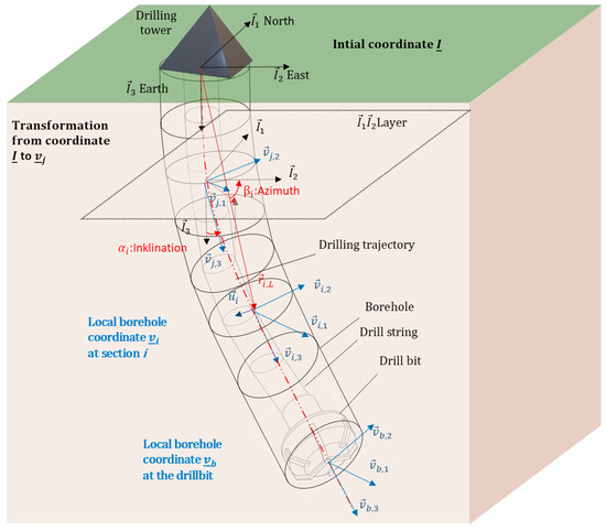
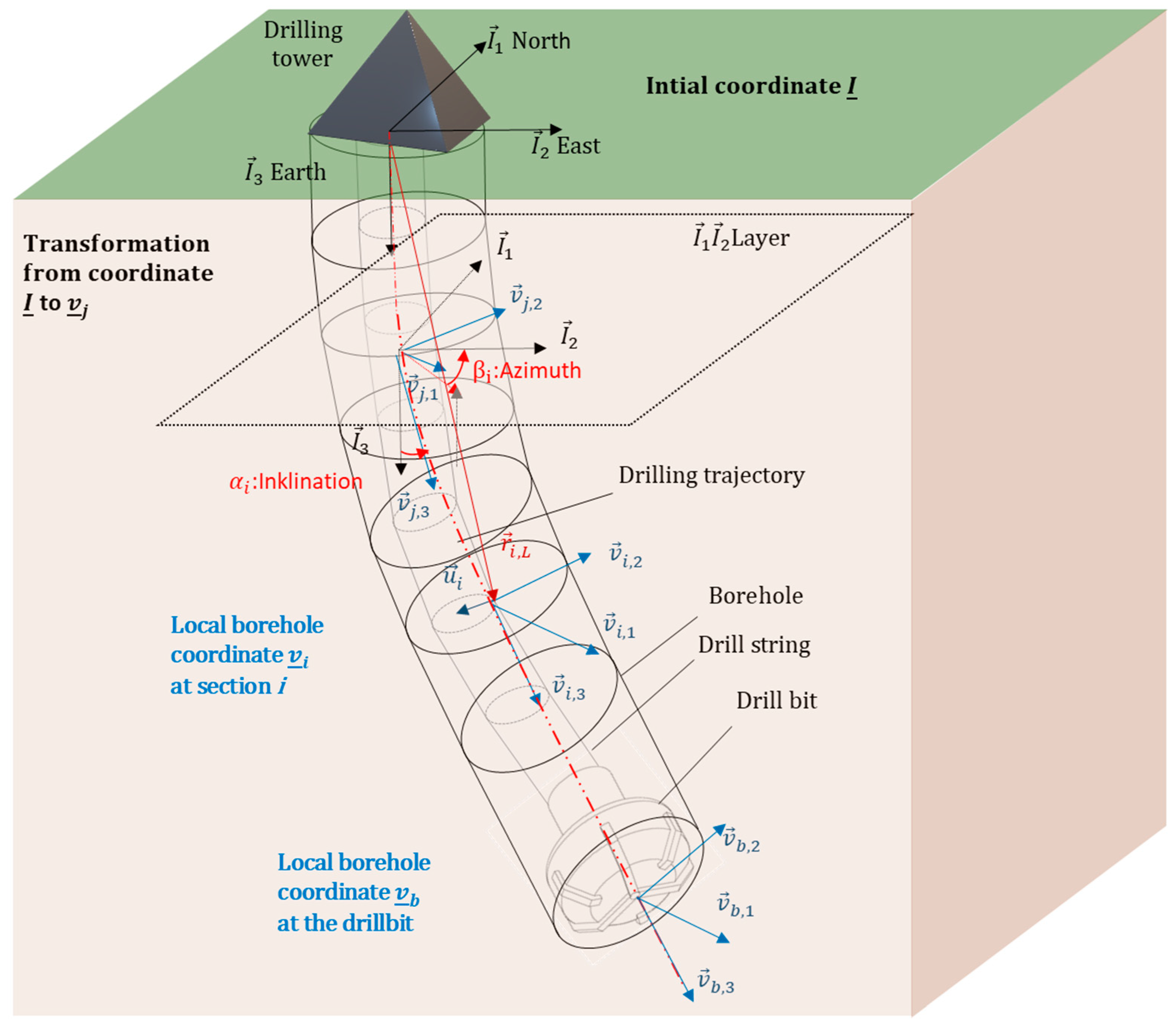
An inertial coordinate system is used to describe the borehole, which is located on the borehole centreline at the Earth’s surface, see Figure 1. The drilling trajectory is described by its centreline , where is the arc length along the borehole centreline. The borehole cross-section is typically assumed to be ideally circular in sections. In addition, a description of arbitrary cross-sections, as used in [21], can be implemented.
Figure 1.
Model of a drill string in a borehole with its reference and local coordinate systems.
Drilling trajectories are typically specified by discrete points along the borehole. In addition to the measured depth, the discrete points contain information about the inclination angle from the vertical and the azimuth angle , which indicates the deviation from the north direction. The minimum curvature method generates a continuous spatial curve that is continuous between two points and ensures a continuously differentiable curve of the coordinates over the arc length along the borehole centreline (). Ostermeyer [20] also introduced local coordinates along the borehole path to describe the motional behaviour of the string in the borehole. With the abbreviation for the partial derivative according to the arc length s, the tangent base vector becomes
The base vector points towards the centre of curvature and completes the orthonormal base
The transformation from the inertial base to the fixed-borehole base can be described in terms of elementary rotations with the azimuth , the inclination and about the vertical axis as
where is the total rotation matrix.
2.2. Equations of Motion of the Drill String
First, the main modelling approaches to describe the drill string kinematics and the strain variables are presented. The position of the deformed drill string in the borehole over the time t is described by Ostermeyer [20], starting from a displacement relative to the borehole centreline with
where is the vector to the borehole centreline of the ith borehole section and are the local displacements. The strain of the drill string element modelled as a beam is given by
where only terms up to order 2 are considered in the calculation [10,20]. By deriving the displacement by the arc length, Ostermeyer [20] obtained an expression for the strain . The normalised vector is tangent to the beam and is used to construct a base attached to the drill string. The transformation from to gives
where the total rotation matrix describes the three successive rotations according to the Cardan angles , and . Deriving by the arc length s yields
The Darboux matrix contains terms for the bending and torsion , and has the form
The total bending of the beam element is given by .
To derive the equation of motion of the drill string, Ostermeyer [20] used Hamilton’s principle of least action. The integral form of the equation of motion is
where T is the kinetic energy, is the energy of deformation and W is the work of the external forces. The kinetic energy of a rigid body is given by
where are the velocities relative to the displacement and are the angular velocities. is the material density, is the circular area of the drill string and are its rotational inertias. Since the rotation around the longitudinal axis of the drill string dominates the dynamic behaviour of the drill string, it is assumed that the moments of inertia and the angles are very small, and therefore negligible [20]. For the same reason is set equal to the time derivative of the cardan angle . It is also assumed that , so that the kinetic energy in the 3-direction can also be neglected [8]. This leads to a simplified equation for the kinetic energy
The deformation energy is
where and are drill string stiffness terms. A detailed discussion of the strain variables can be found in [10,20]. It is usually assumed that the strain is zero. This eliminates one degree of freedom. However, it should be noted that the axial displacement is not equal to zero and can be determined from the lateral degrees of freedom. The same applies to the static axial force. The work of external forces can be divided into volume forces acting on the whole drill string and local point forces acting on the nodes of a drill string element. For point-symmetric and constant string cross-sections, the work of the volume forces is given by
where is the distributed force per length. This includes forces such as weight and fluid damping for instance. The work of local point forces is given by
By calculating , and the variations , and can be obtained. This gives the equation of motion (9). However, this can only be solved analytically for certain boundary conditions, see [30]. To obtain solutions for arbitrary boundary conditions, the entire drill string is discretised with N discrete beam elements according to the finite element method (FEM).
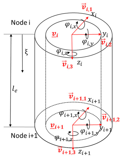
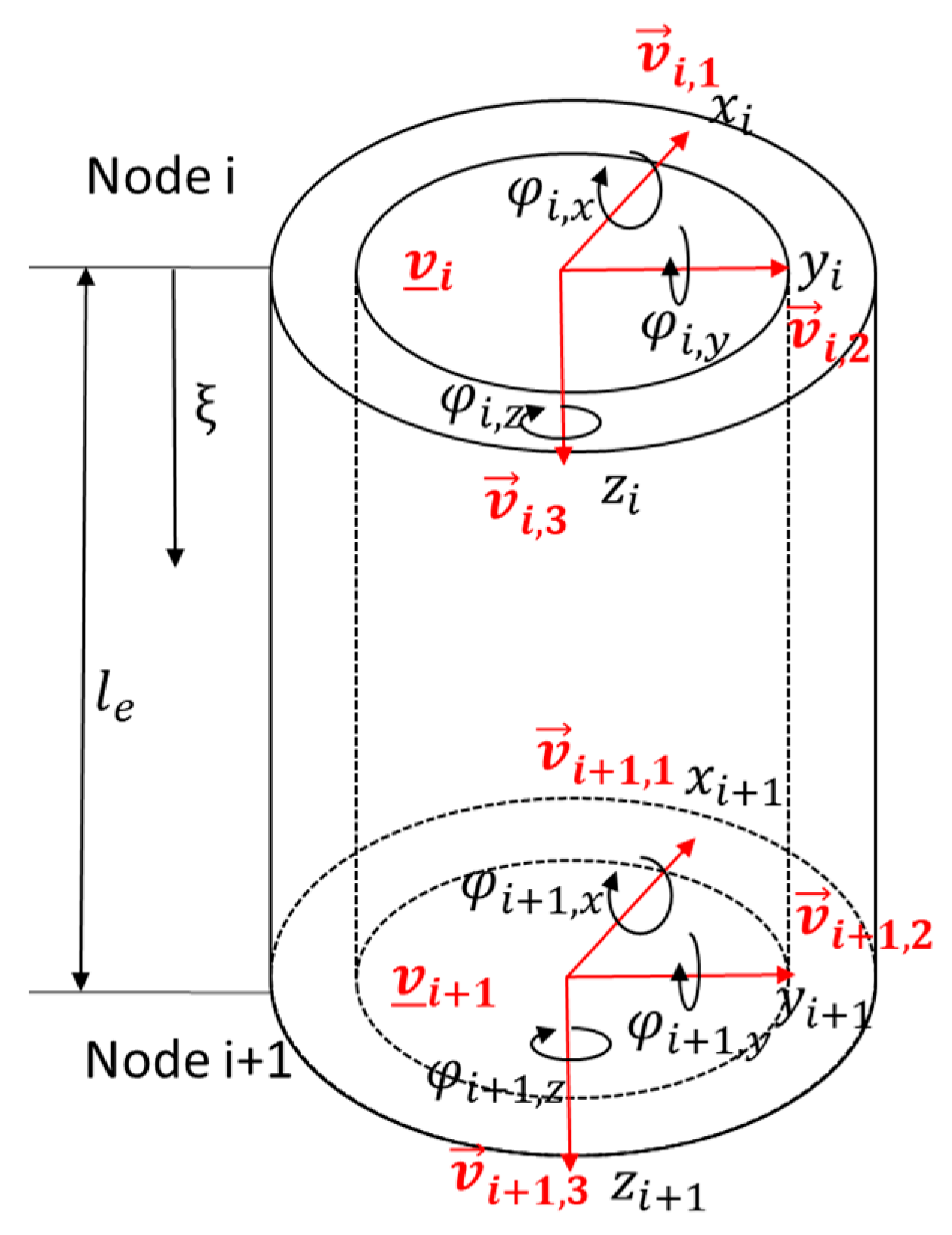
According to Figure 2, nodes 1 and 2 each have six degrees of freedom. Three of these are for translation () and three for rotation (). The focus of this work is on the study of lateral and torsional vibrations and, with the assumptions made above, the translation in the z-direction is neglected and five DOF per node are obtained. The generalised variables of a FEM node i are summarised in the column matrix u
where in and are the lateral displacements perpendicular to the borehole centerline. The tilt angles about the axes and are described by and , respectively. The rotation around the z-axis, which is also used to drive the drill string on the surface, is described by the angle . Following the standard approaches for FE beam elements, third-order experimental functions are selected for the bending about and , while the torsion about the longitudinal axis is described with a linear experimental function. In addition, the appropriate modelling of the external forces plays a crucial role for a realistic description of the drill string dynamics. In addition to the volumetric forces, which describe the self-weight and lift of the drill string, time-varying and event-driven forces are also essential. These include forces from the contact between the drill string and the borehole wall, from the cutting process at the drill bit and from lateral imbalance forces.
Figure 2.
Single FEM element.
The equations of motion for the entire drill string can be written as
where is inertia matrix, is the damping matrix, is the stiffness matrix and is a column matrix summarising all external forces. The stiffness matrix also includes non-linear components from the elastic restoring forces, also with respect to the arbitrarily curved borehole path. Material damping can be described by Rayleigh damping, as often used in FEM. Based on practical experience, the damping due to the drilling fluid can also be approximated in a rough first approximation by selecting appropriate parameters when creating the damping matrix . Dissipation due to friction and impact of the drill string against the borehole wall is also considered by unilateral constraints, where the constraining force is the contact normal force. The associated tangential contact force can be described by a friction law. As this contact formulation in OSPLAC is also elementary for modelling at the drill bit, it is described in more detail below.
2.3. Contact between Drill String and Borehole
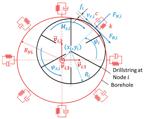
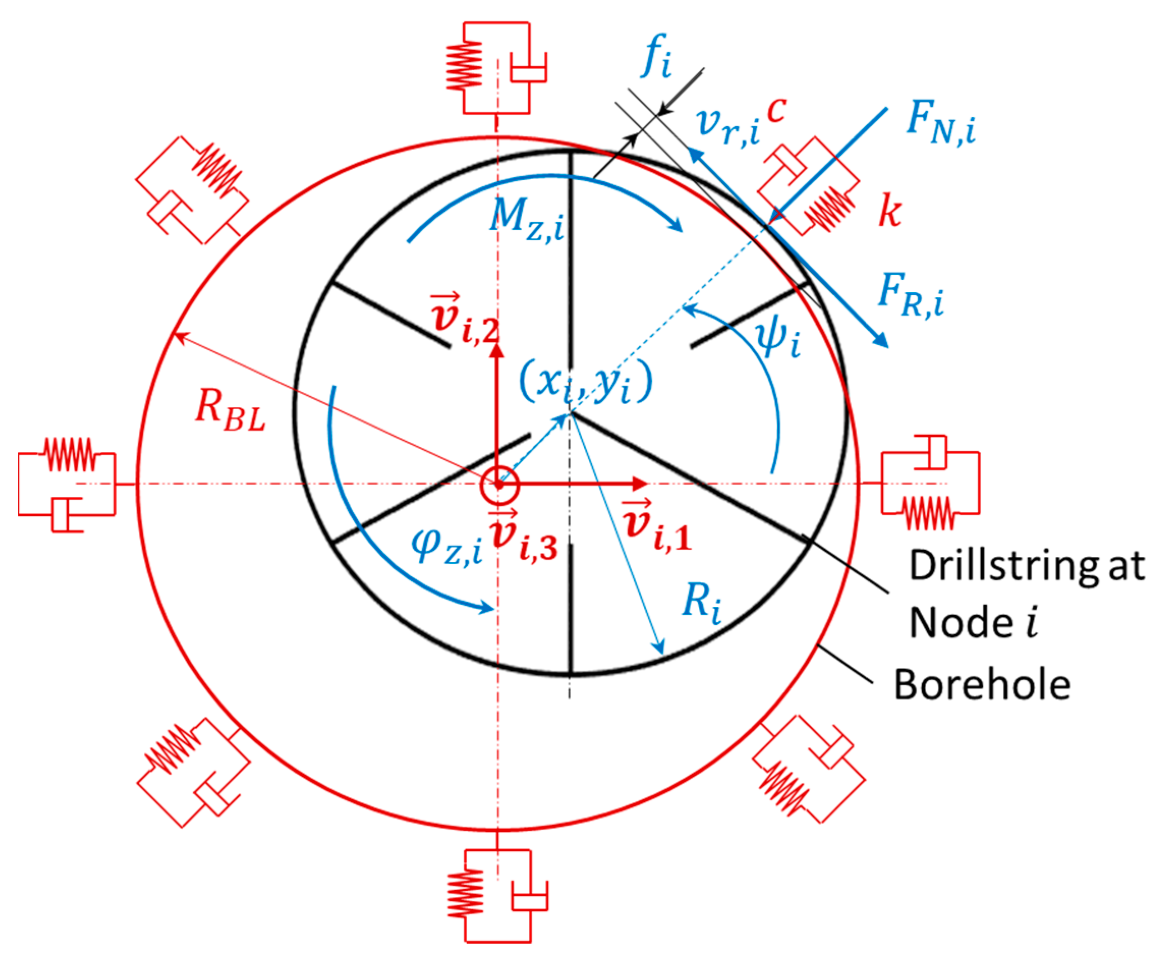
The contacts between the drill string and the borehole are modelled by unilateral constraints, which ensure that the drill string always remains within the borehole, see Figure 3. This macroscopic contact model assumes that the borehole is elastic and the drill string is a rigid body, resulting in normal forces, wall friction forces and torques at the element nodes of the drill string. The borehole parameters such as contact stiffness k, the contact damping c and the friction factor μ are important for the modelling and characterising of the contact dynamics. In addition, these contacts are event-driven and can be highly dynamic, especially during impacts. The modelling used in OSPLAC [20] is explained in more detail here, as it is also used to model the drill bit in this paper.
Figure 3.
Contact model at drill string node .
The drill string at node is assumed to be enclosed in a cylindrical borehole with a clearance
which is the difference between the borehole radius and the drill string outer radius .
When the drill string penetrates the borehole wall as shown in Figure 3, a normal force consisting of stiffness and damping forces occurs
where the depth of penetration is
and the speed of the penetration is
where are the lateral displacements and are the associated velocities of the drill string-node with respect to the base vectors of the borehole fixed coordinate system . The angle in Figure 3
describes the angle of the rotating drill string around the tangent base vector and is also used as a measure to identify whirl vibrations. Thus, the normal force vector at node is
When the rotating drill string node is pushed against the borehole by the normal force , a friction force and torque are generated
where is a velocity-dependent coefficient of friction, and is the relative velocity depending on the torsional rotational speed of the drill string node around its own axis and the whirling velocity . The relative velocity is given by
with the whirling velocity
Consequently, the frictional force vector at node is given by
3. Mesoscopic Drill Bit Model
During the deep drilling process, the drill bit interacts with the drill string and the rock. The drill string exerts forces (e.g., normal force) and torques (e.g., torque on bit) on the bit to drill the rock. On the other hand, the rock exerts resistance forces and torques. This bit–rock interaction is the main source of excitation of drill string vibration. In the introduction, we briefly described different approaches to bit modelling that approximate these interactions at different levels of detail.
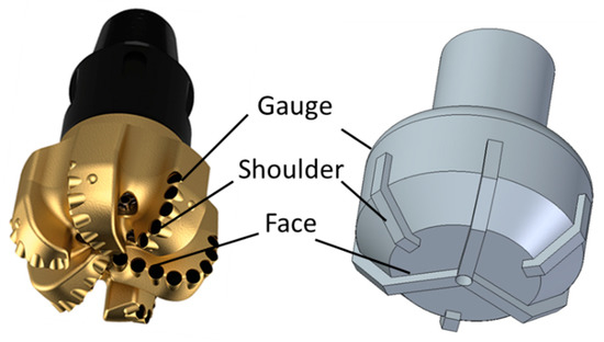
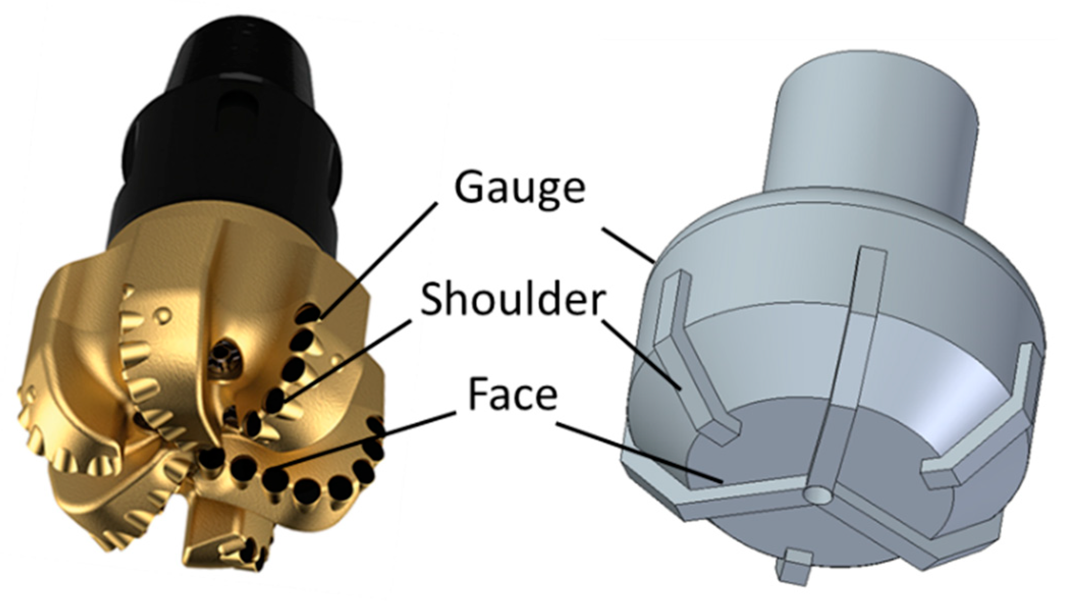
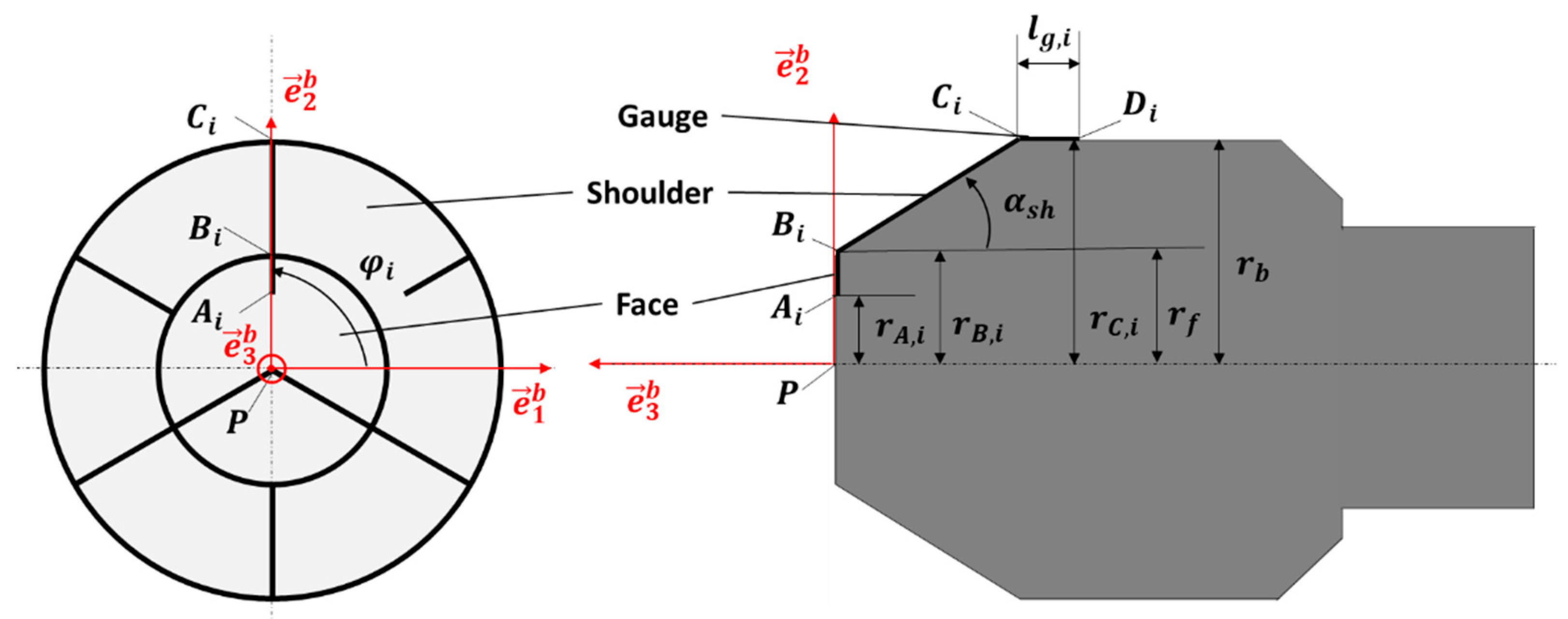
The new modelling approach focuses on the description of PDC bits, which are currently the most used types. PDC bits mainly cause lateral and torsional vibrations in the drill string. Figure 4(left) shows a PDC bit consisting of six cutting blades with cutting elements on the face, the bit shoulder and the gauge. As shown schematically in Figure 4(right), the bit is modelled as a rigid body and the cutting forces on the drill bit are not described for each individual blade but distributed over the blades. The modelling approach is therefore independent of the number and positions of the cutting blades.
Figure 4.
(Left) PDC drill bit, (Right) schematic representation of the mesoscopic drill bit model.
In contrast to established macroscopic drill bit models, which determine the torque on the bit only from the aggressiveness of the bit and the weight on the bit, the mesoscopic drill bit model provides the system-inherent lateral forces in addition to the torque on the bit in the case of asymmetries at the drill bit or rock inhomogeneities. To derive the model, the kinematics of the cutting blades are first determined. Then an approach is developed to determine the cutting forces on the blades, considering the distributed normal and contact forces and the bit aggressiveness. By coupling with the drill string model in OSPLAC, complex time domain simulations can be performed to describe the complex drill string dynamics. In this way, the effect of rock inhomogeneities on the dynamics of the entire drill string can be investigated with respect to the bit cutting geometry. The mesoscopic approach also has significant computational time advantages over complex drill bit models, allowing parameter and sensitivity studies to be performed in pre-well analyses.
3.1. Mesoscopic Drill Bit Kinematics
3.1.1. Coordinate Systems and Geometrical Variables
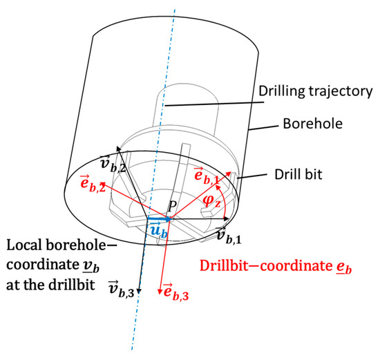
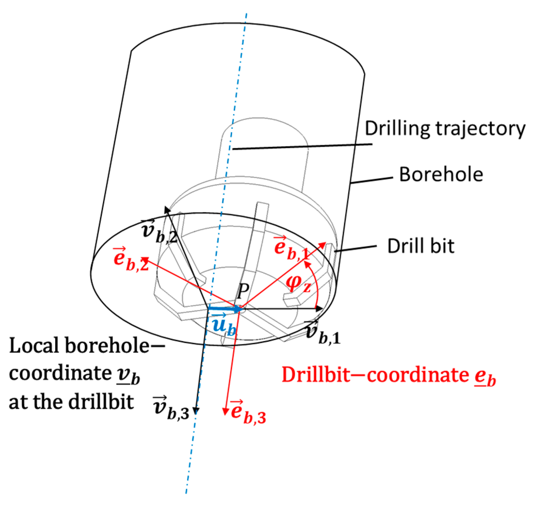
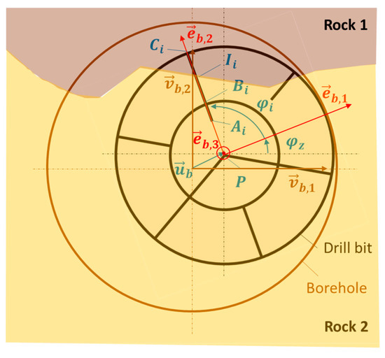
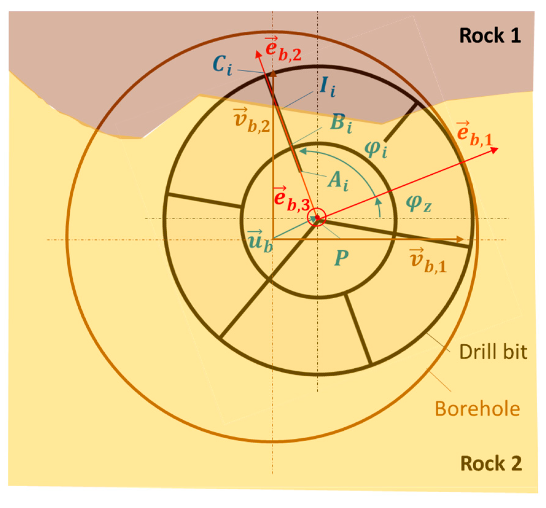
Analogous to the procedure in OSPLAC and for the implementation, a borehole- fixed-coordinate system is introduced at the centre of the bottom of the borehole, see Figure 5. The vector points in the direction of the borehole trajectory. The orientation of this coordinate system is determined by the two rotations around the azimuth and inclination with respect to the initial coordinate system as described in Equation (3).
Figure 5.
Coordinate systems at the drill bit and borehole.
We also introduce a drill-bit-fixed-coordinate system at point P, see Figure 5, to describe the bit translation and orientation. During drilling, only a minimum radial clearance remains between the drill bit and the rock. In this work, a realistic value of 1/16 inch has been chosen [31,32]. It is therefore assumed that the deflection of the bit axis against the borehole axis is negligible, so that
As the drill bit rotates around the axis with the angle , the drill-bit-fixed-coordinate system rotates around the same axis with the angle
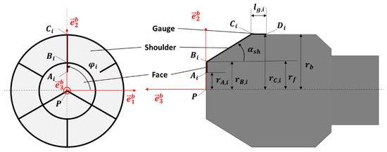
First, the geometric position of the cutting blade on the face, shoulder and gauge of the drill bit is described. For this purpose, characteristic points, see Figure 6, are defined by position vectors in the drill-bit-fixed-coordinate system
where is the angle between blade and axis , depending on the number of blades n. and are the distances between the points and , respectively, and the centre axis of the drill bit. is the shoulder angle. According to Figure 6, the lengths of the cutting blades
are given by the distances between the points defined by Equation (29).
Figure 6.
Dimensions of the cutters on the fixed mesoscopic drill bit.
The gauge length is not included here, as we will assume that the axial force is distributed only at the front side. The gauge length is relevant for considering the lateral normal forces on the drill bit leading to frictional contact with the wall.
For the drill bit dynamics, corresponding lever arm lengths are also required to describe the torque on the bit at . Based on [32], we assume that the weight on the bit is distributed as a constant line load on all blades. The cutting forces of each cutting element are then determined by the aggressiveness of the cutting element. Since the cutting force on an element is almost independent of the cutting speed [31], it is also assumed that the resulting force acts in the centre of the cutting blade. For the lever arm at the bit shoulder blade , this gives
On the face side, the cutting forces can lead to torsional torques with lever arms
Consequently, the resulting lever arm for the torsional torque on the front side (face and shoulder side) is
The lever arm related to the total torque on the bit can now be expressed for n-blades as
The position vectors from Equation (29) can be transformed using Equation (28) from drill bit to drill hole fixed coordinates:
The kinematic variables are available as a function of time, where describes the lateral displacement of the drill bit and the angle of rotation due to the drill string rotation.
3.1.2. Consideration of Different Rocks in the Cutting Zone
A main objective of this paper is to describe both the drill bit and drill string dynamics when drilling through different types of rock simultaneously.
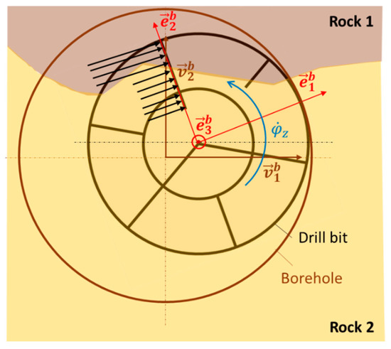
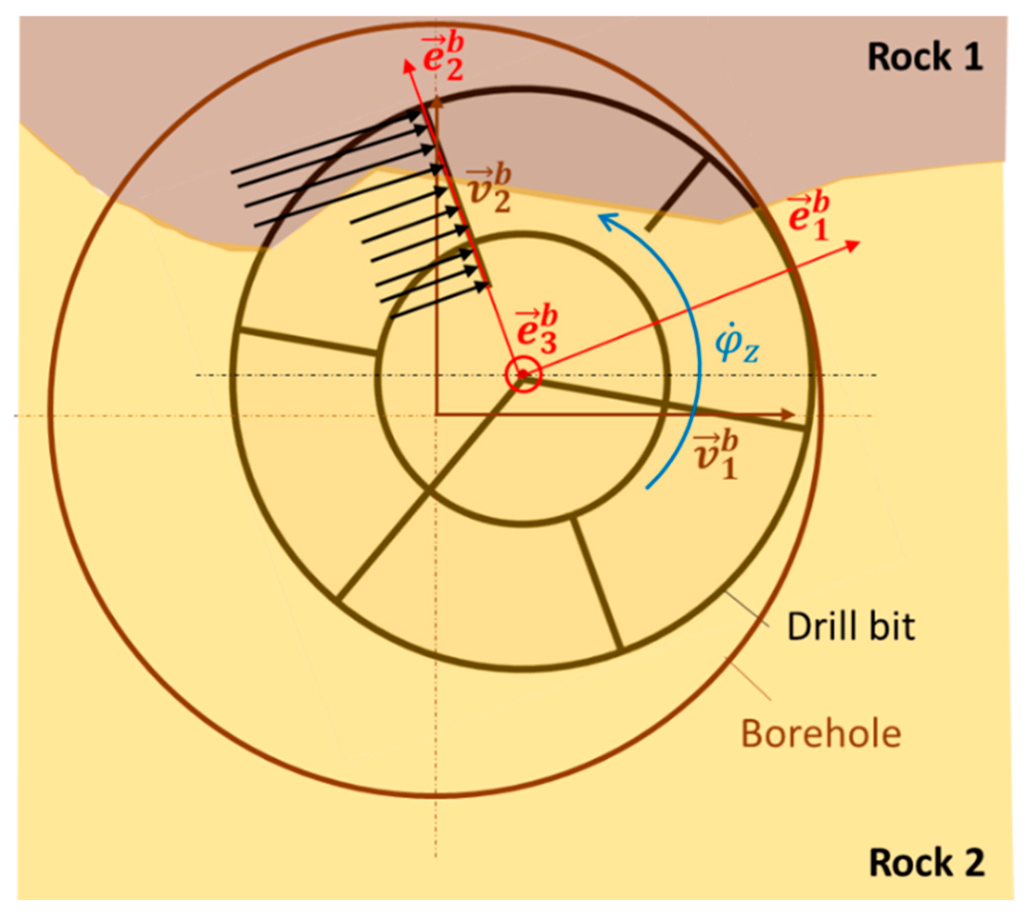
Due to the positioning of the cutting blades on the drill bit, the individual contact of each blade with the type of rock is different. It is therefore essential to determine the parts of the blades that are in instantaneous contact with rock 1 and those that are in contact with rock 2 (see Figure 7). In principle, the number of rocks in the model approach is not limited. Here, we first assume that no more than two rocks occur in the cutting zone. To determine the lengths, we need to identify the position of the intersection between rock 1 and rock 2 on the drill bit. There are four cases for a blade :
Figure 7.
Dimensions of the cutters on the rotating mesoscopic drill bit depending on the rock-type contact.
Case 1: Blade is completely inside rock 1 with the lengths
and the corresponding lever arms
Case 2: Blade is completely inside rock 2 with the lengths
and the corresponding lever arms
Case 3: The point of intersection is between and , and the parts of the blade in contact with the rocks 1 and 2, respectively, are defined as
To calculate the lever arms, we need to find the midpoint between and as well as the midpoint between and, which are given by
This yields to the following lever arms
Case 4: the point of intersection point lies between and and the parts of the blade in contact with the rocks 1 and 2, respectively, are defined as
The midpoint between and as well as the midpoint between and are
and the lever arms yields to
3.1.3. Lateral Contact between Bit and Borehole
For the later calculation of the gauge cutting forces, the penetration and the penetration velocity of each gauge blade must be calculated. The procedure is the same as the calculation of the wall contact forces in Section 2.3. Similar to Equations (19) and (20), the penetration distance and velocity at the point are given by
where are the displacements and are the velocities of the cutting blade at point with respect to of the fixed borehole system. The angle describes the angle of the rotating bit around the borehole rotation axis and is also used as a measure to identify whirl vibrations. The relative contact speed at the drill bit
depends on the rotation speed of the drill bit around its own axis . and the whirling speed.
3.2. Mesoscopic Drill Bit Dynamics
Using the derived geometric and kinematic equations, we can now determine the cutting forces on the cutting blades as a function of the drilling process parameters on the bit using bit-specific and rock-specific resistance curves. The resulting forces and torques on the drill bit are directly derived from the dynamic calculation, which excite the entire drill string to various vibration phenomena.
3.2.1. Resistance Coefficient of Cutting Blades
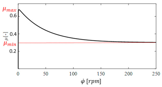
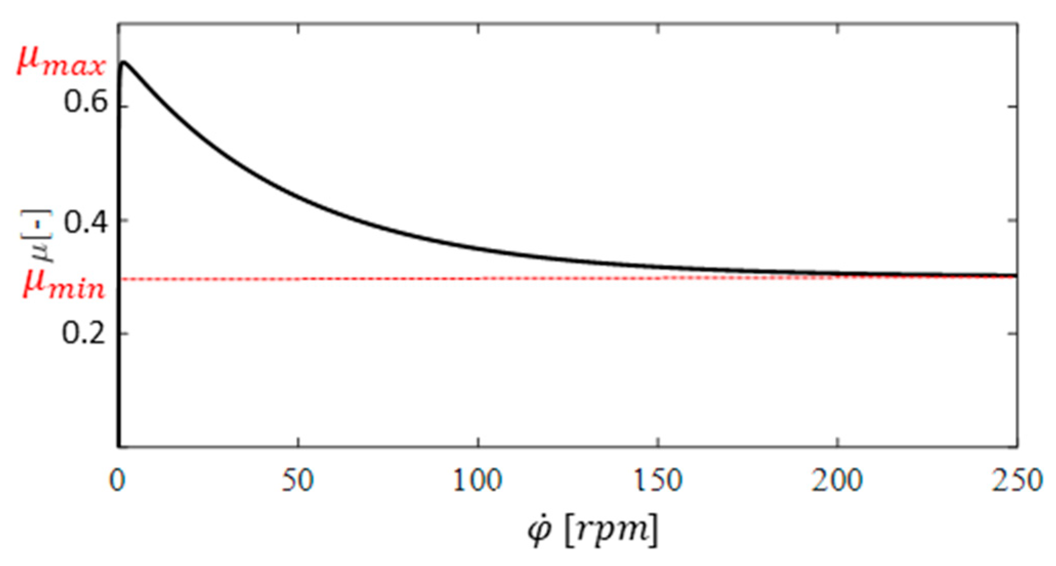
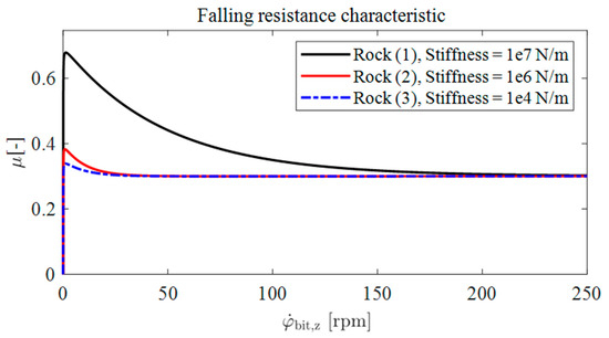
In the early 1990s, initial laboratory results indicated a decrease in mean bit torque with increasing rotational speed, which was interpreted as a major cause of self-excited torsional drill string vibration [1]. The torque on the bit can be determined experimentally in field tests or laboratory tests specifically for a drill bit and a rock type as a function of drilling parameters. The bit-specific resistance coefficient, which normalises the bit torque with respect to the weight on bit , is referred to in Figure 8 as the falling resistance characteristic. can then be derived from the falling resistance torque at the drill bit via
where is the lever arm of the bit, considering the cutting blades on the frontal side.
Figure 8.
Falling resistance characteristic with respect to the rotational speed at the bit.
In this work, the characteristic curve of [33] will be used, which is given by
The parameters and are used to describe the shape of the characteristic.
3.2.2. Cutting Force and Torque Analysis on the Frontal Side (Face and Shoulder Cutters)
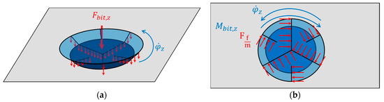
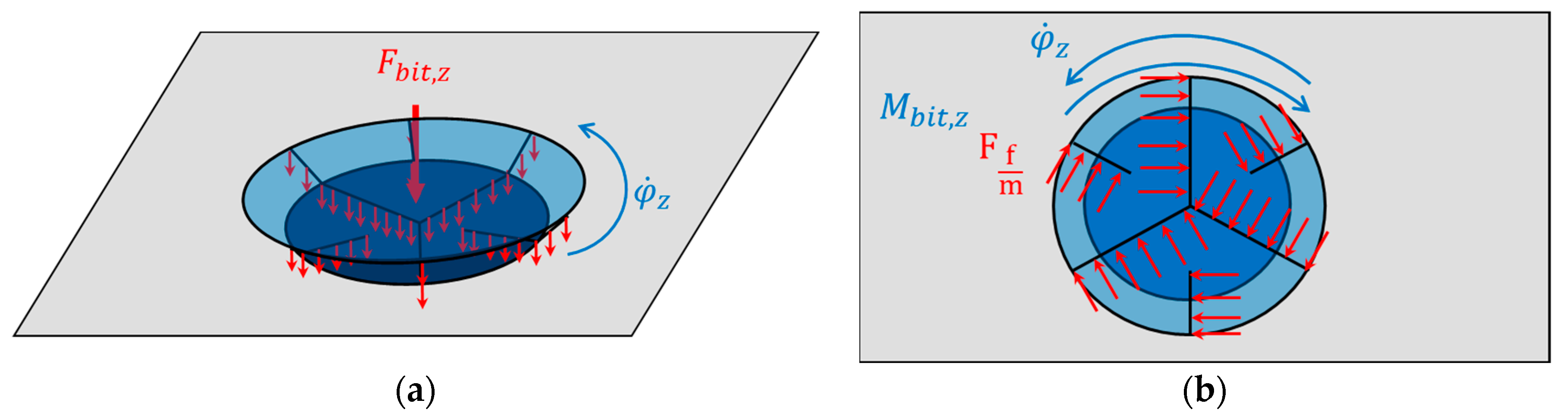
When drilling, the bit is subjected to an axial normal force, which is distributed on the cutting blades of the bit face, see Figure 9a.
Figure 9.
(a) Normal force distribution on the frontal cutters. (b) Cutting force distribution.
The normal force per length is assumed to be
and the cutting force per length
is then defined as the product of the normal force and the resistance coefficient from Section 3.2.1.
Based on Equation (31), the normal force
is the part of the axial force that presses on each cutting blade , assuming that the face is in permanent contact with the bottom of the borehole. By multiplying the resulting face cutting force on each blade
with the lever arm of the front blade, we obtain the resistance torque
of each cutting blade. The sum of all the torques gives the torque on the bit
should be equal to the torque on bit obtained from the falling torque curve in Section 3.2.1. For further analysis of the lateral stability, the components of the cutter force in the plane
are considered. However, when drilling through formation splits, the cutting forces distributed on a blade are unequal due to the different resistance coefficients, see Figure 10. Here we distinguish between the cutting forces on the face and shoulder sides and between those in contact with rock 1 and rock 2, which yields to
using the lengths and introduced in Section 3.1.2. The resulting cutting force is the sum of these distributed forces on blade
and the force components in the plane can then be formulated as
Figure 10.
Cutting force distribution on cutting blade in contact with rock 1 and rock 2.
The cutting torques
are the result of the multiplication of the cutting forces from Equation (47) by the lever arms and of each blade part from Section 3.1.2. The sum of these torques yields the resultant torque
on each cutting blade. The components of the resulting cutting force on the front side
are defined as the sum of all force components of the cutting blades and the cutting torsional torque on the front side of the bit
as the result of the multiplication of these forces by the lever arms and . Consequently, the external force and torque vector of the front side of the bit is
3.2.3. Cutting Force and Torque Analysis on the Gauge Side
The cutting forces and torques on the gauge side are determined in a similar way to the frictional forces between the drill string elements and the borehole in Section 2.3. In fact, when a cutting blade penetrates in the borehole wall, normal forces
consisting of stiffness and damping forces depending on the rock act in contact with the gauge. The resulting normal force vector can then be expressed as
When the rotating gauge blade is pressed with normal forces against the hole with a resistance factor of the resulting cutting force and cutting torque are
where is the relative velocity on the gauge side of the bit, see Equation (24).
Consequently, the force and torque vector at the gauge of blade can be expressed by
Therefore, the resulting normal force vector acting on all sides of the gauge is
and the resulting resistance force and torque vector is defined as
3.2.4. Forces and Torques on the Drill Bit
The resulting forces coming from the cutting process on all sides of the bit (face, shoulder and gauge) are summarised in the vector
The lateral excitation on the bit is generated by the force components () of the torsional resistance forces on the cutting blades and yields to
4. Case Studies with the New Mesoscopic Drill Bit Model
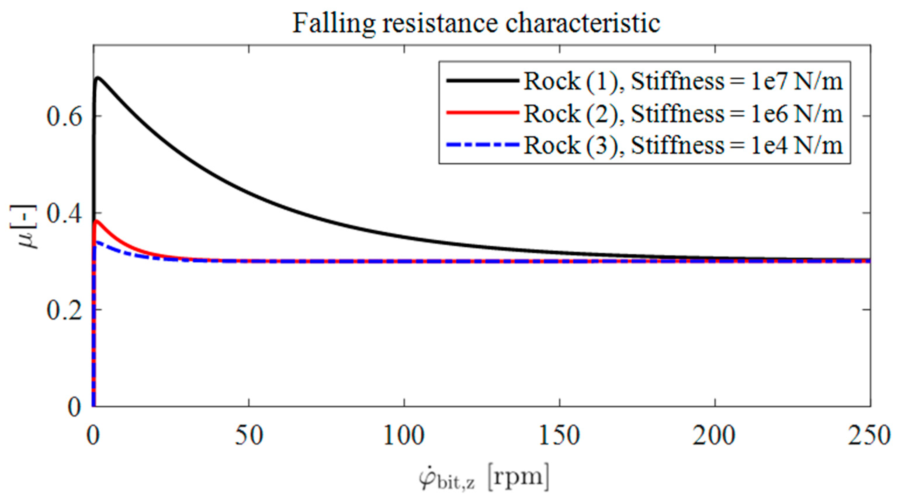
In the following section, an explanatory drill string simulation using the mesoscopic drill bit model is analysed to determine the influence of the rock inhomogeneity on the torsional and lateral dynamics of the drill string. The focus of this study is on the excitation source of the bit (blades)–rock interaction due to the modelled resistance forces and torques and the corresponding lateral forces. Therefore, other forces and phenomena such as mass imbalance or fluid forces are neglected. For the estimation of the cutting forces, two falling resistance characteristics with respect to the angular velocity at the drill bit were assumed for two different rocks: (1) a hard rock leading to a stick–slip tendency, (2) a soft rock leading to steady-state behaviour and (3) a very soft rock (see Figure 11). The simulations in the case studies are carried out using a drill string with the following parameters (Table 1).
Figure 11.
Falling resistance characteristic with respect to the rotational speed at the bit for rocks (1), (2) and (3).
Table 1.
Drill string parameters.
Table 2 gives an overview of the case studies: the drill string drills through a sandwich formation consisting of rock 1 and a thin layer of rock 2. Rock 1 is characterised by a higher Young’s modulus resulting in a higher stiffness and a high resistance at lower rpm resulting in a greater tendency to cause stick–slip (see Figure 11). Rock 2, on the other hand, is a soft rock with a lower stiffness and a lower tendency to stick–slip.
Table 2.
Case studies.
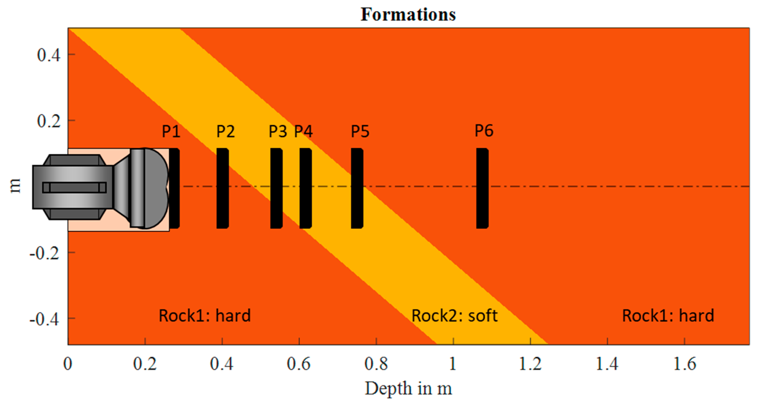
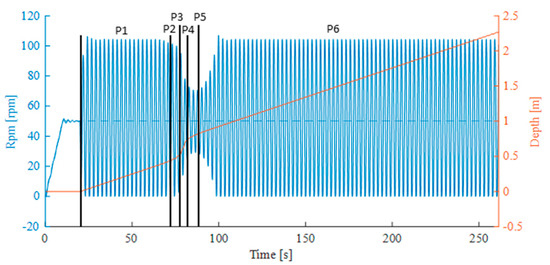
In Figure 12, six positions of the drill bit are selected to be analysed in the following case studies:
- P1, P6: the bit is in contact with rock 1 only.
- P2: 25% of the bit surface is in contact with rock 2 and 75% with rock 1.
- P3: 25% of the bit surface is in contact with rock 1 and 75% with rock 2.
- P4: the bit is in contact with rock 2 only.
- P5: 50% of the bit surface is in contact with both rock 1 and 2.
Figure 12.
Drilling through a sandwich formation with an inclination of 45°, P1–P6: selected observation points of the dynamics.
4.1. Case Study 1: Torsional Stability Map
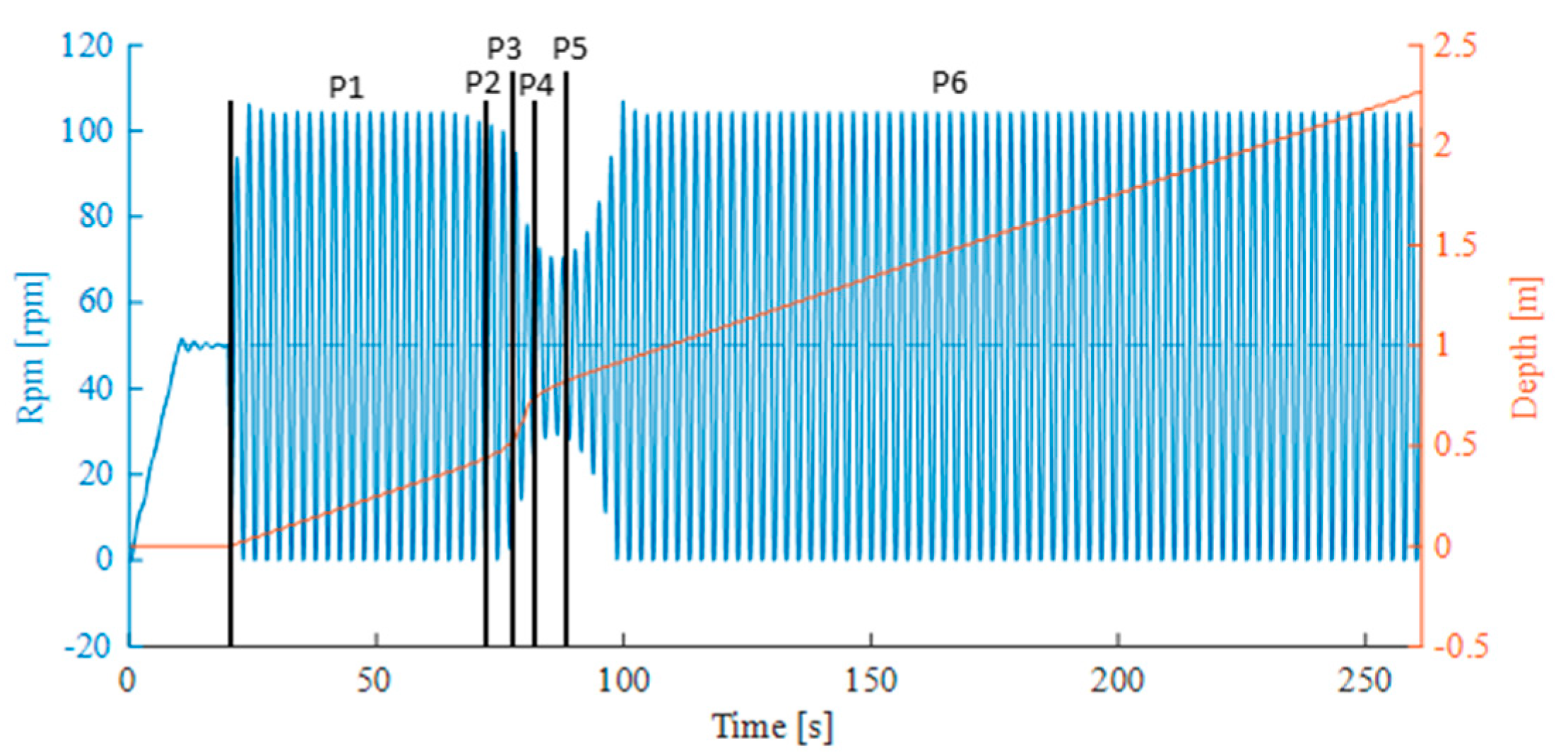
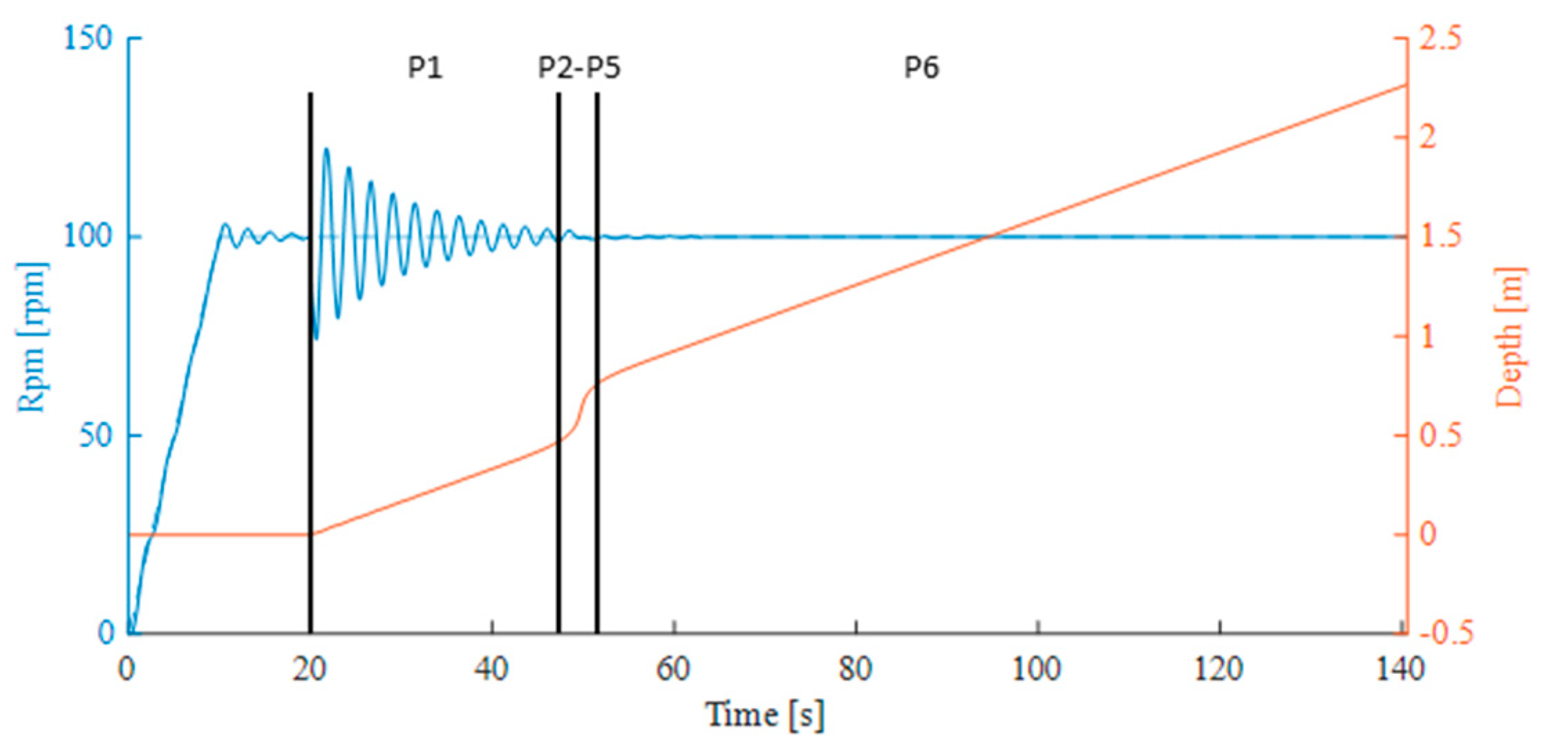
In case study 1 we only focus on the torsional vibrations at the bit. The occurrence of stick–slip depends on the normal force on the bit and the rotational speed of the drill string ( and RPM). So two simulations are run with a constant normal force and two rotational speeds , see Figure 13, and , see Figure 14.
Figure 13.
Torsional oscillation of the bit at when drilling through formations.
Figure 14.
Torsional oscillation of the bit at when drilling through formations of Figure 13.
At the start of each simulation (first 10 s) the top drive speed is linearly increased to the target speed. For the next 10 s, the target speed is maintained but the target normal force is not set to avoid any outward oscillation that could increase the tendency to stick–slip. After 20 s of simulation time, the drilling operation is started by setting the normal force to the target value.
At the bit starts to drill into hard rock 1, causing stick–slip. As the contact with rock 2 increases due to the formation change (see positions 3 and 4), the bit tends towards a steady state. When the formation changes back to rock 1, the drill string becomes unstable again. At , the drill bit oscillates towards a steady state from the beginning to the end of the formation change.
In the classical rigid-cylinder bit models, torsional stability depends, among other things, on only two operational parameters: normal force and bit rotational speed. As a result, corresponding stability maps are two-dimensional and transition phases during formation changes cannot be represented. In addition to normal forces and bit speed, the results of this case study show that we need a third dimension covering another operational parameter, namely the contact area between the bit and the rock, when drilling in inhomogeneities.
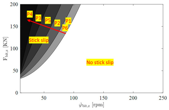
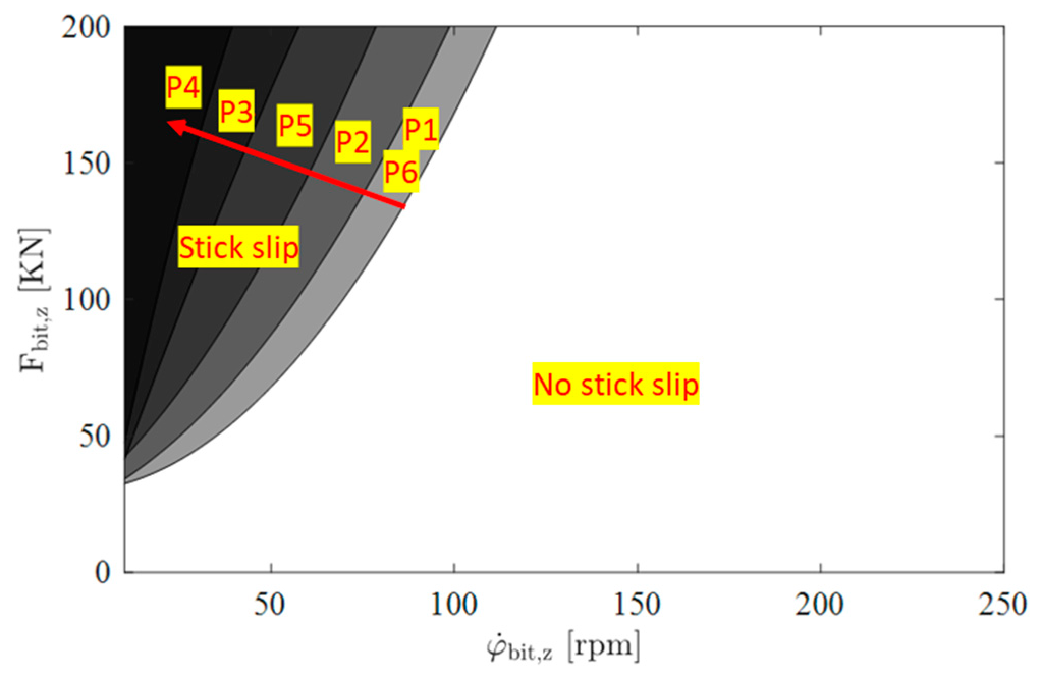
One of the advantages of the mesoscopic drill bit presented in this paper is that it allows the determination of torsional stability maps in inhomogeneous rock formations. To generate these maps, and RPM are varied from 0 to 200 kN and from 0 to 250 rpm, respectively, with a fixed step (5 kN/rpm) and it is assumed that the drill bit is drilling in a fixed position from P1 to P6, see Figure 12.
At each step, a simulation is run for a defined normal force and rotational speed for a long time to allow the system to reach its steady state. As soon as stick–slip occurs, an identification algorithm fills the stability map matrix with one for stick–slip and zero for no stick–slip. In the beginning of this analysis, a method based on scanning all possible (RPM,) combinations was used. However, this was very time consuming. Therefore, an optimised stability map generation algorithm was developed to minimise the number of simulations. This algorithm aims to identify the boundary curve between the stick–slip and no stick–slip zones. Two basic rules were used to do this:
If an value is identified at a certain speed at which stick–slip occurs, then all higher values will also cause stick–slip. In this case, and RPM increase linearly in the next step.
If does not cause stick–slip at a certain speed, only will increase in the next step.
Two zones (stick–slip and no stick–slip zones) are shown graphically in Figure 15: Stick–slip is generally characterised by a high normal force at the bit and low rotational speed RPM. This figure shows different stability zones for six bit positions. The torsional instability zone increases as the contact area between the bit and rock 1 increases.
Figure 15.
Rev/min-F stick–slip stability map using mesoscopic drill bit model in positions P1 to P6.
4.2. Case Studies 2–4: Torsional/Lateral Simulations
These case studies analyse the influence of the formation changes on the lateral and torsional stability of different drill bits (symmetric and asymmetric) and rocks (hard, soft and very soft) is analysed.
Torsional oscillations:
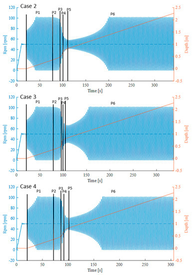
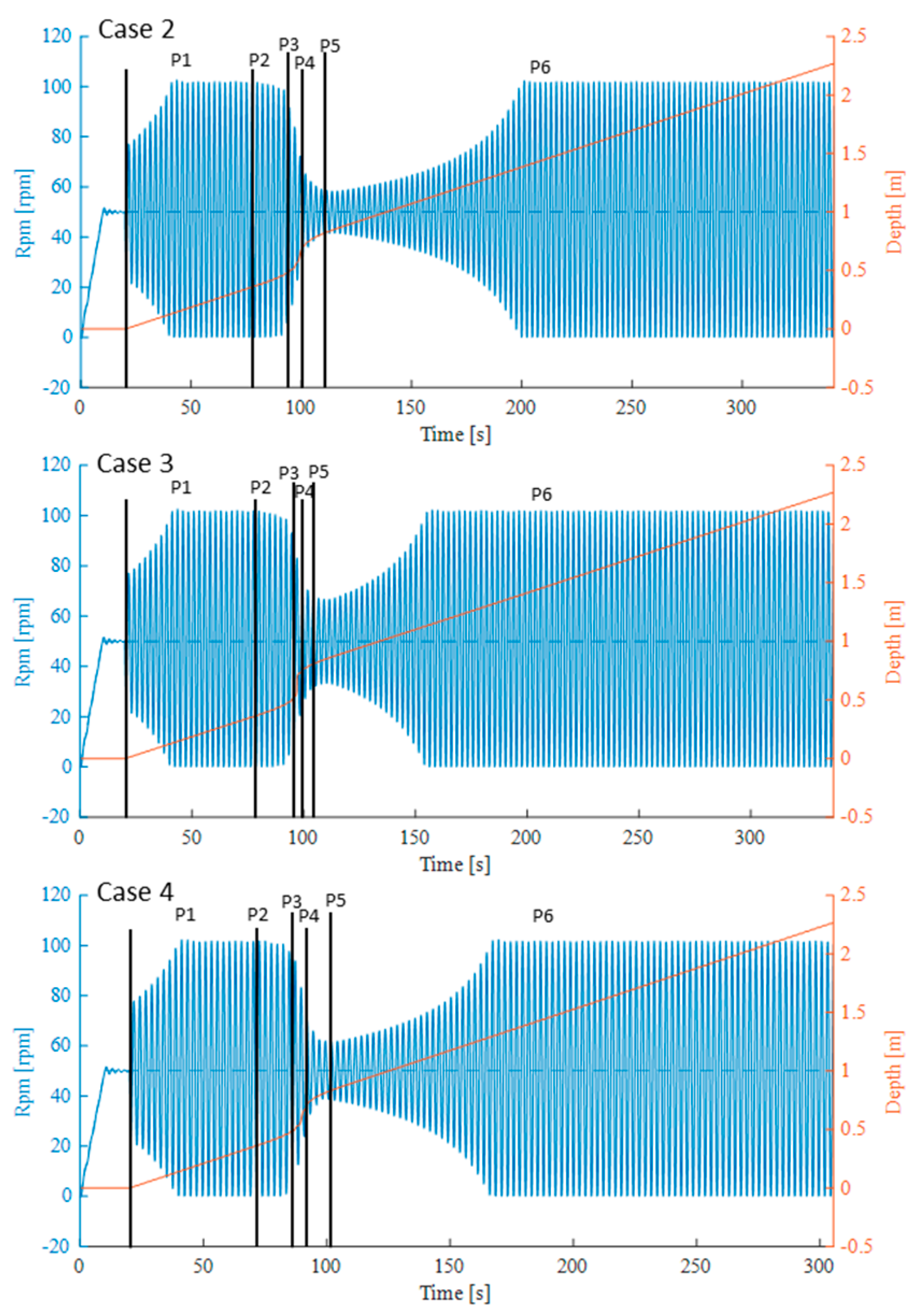
Figure 16 shows the time simulation of the drill string torsional vibration using a symmetric mesoscopic drill bit model when drilling through the sandwich formation of Figure 12. Based on the torsional stability map in Figure 15, the values of 50 rpm and 75 kN will lead to stick–slip when drilling in P1/P6 or P2. For comparison reasons, these positions correspond to the unstable behaviour intervals in Figure 15 where stick–slip vibration is generated. The time intervals where stick–slip decreases are the transition phases from rock 1 to rock 2 and from rock 2 to rock 1. They represent the inhomogeneous bit–rock-contact intervals.
Figure 16.
Time simulation of the torsional oscillation at the bit when drilling through formations of Figure 12.
In case 2, the middle rock (2) is soft, leading to a torsional steady state of the drill bit (from ~100 s). In case 3, the middle rock (2) is replaced by a very soft rock, which leads to a shorter drilling time in rock 2. After leaving the inhomogeneity, the drill bit reaches its torsional unstable state much faster. Case 4 is like case 2 except that the drill bit is replaced by an asymmetric bit. The total drilling time through the formation is shorter than in case 2.
Lateral oscillations:
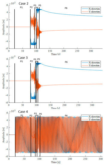
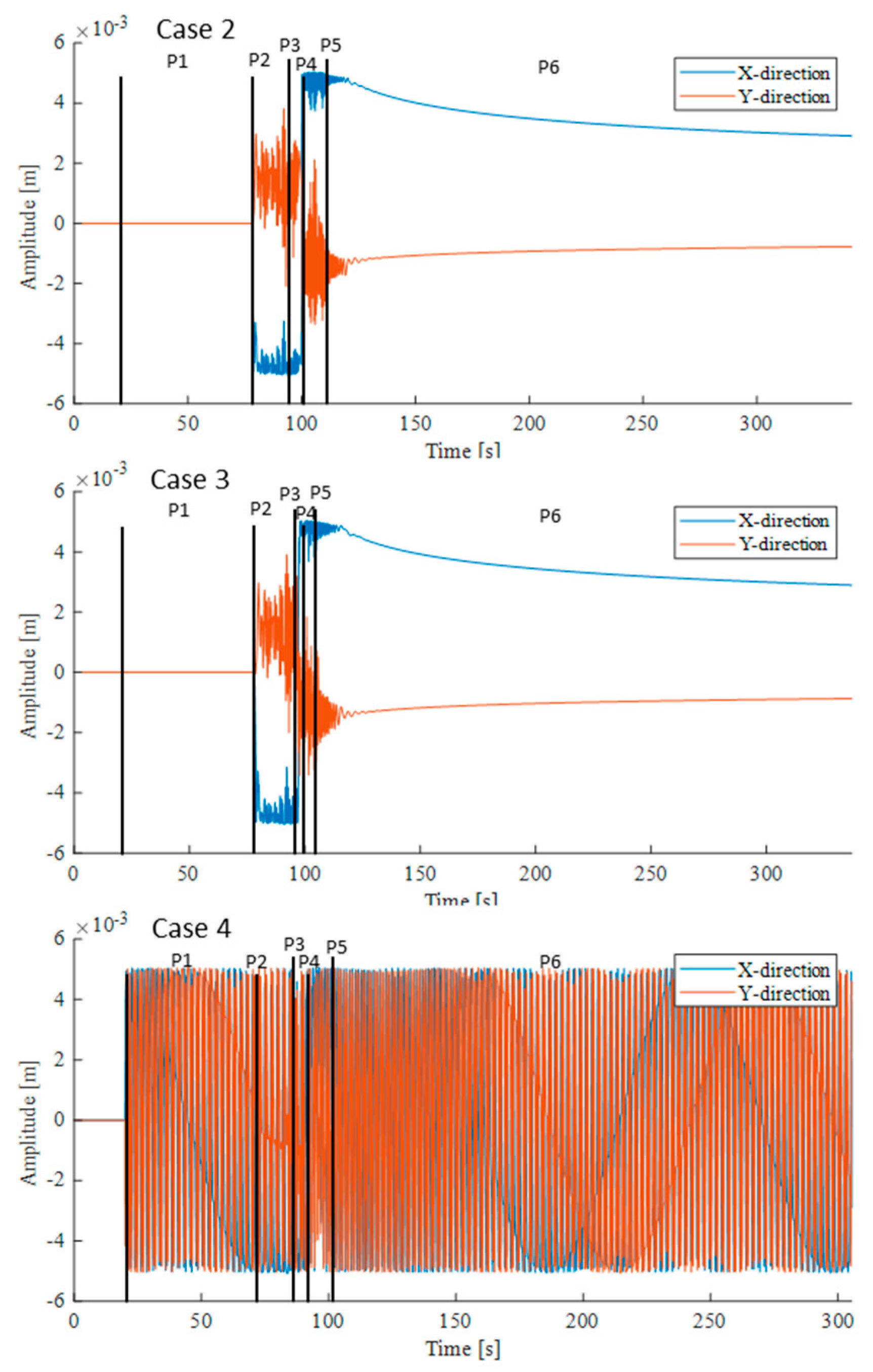
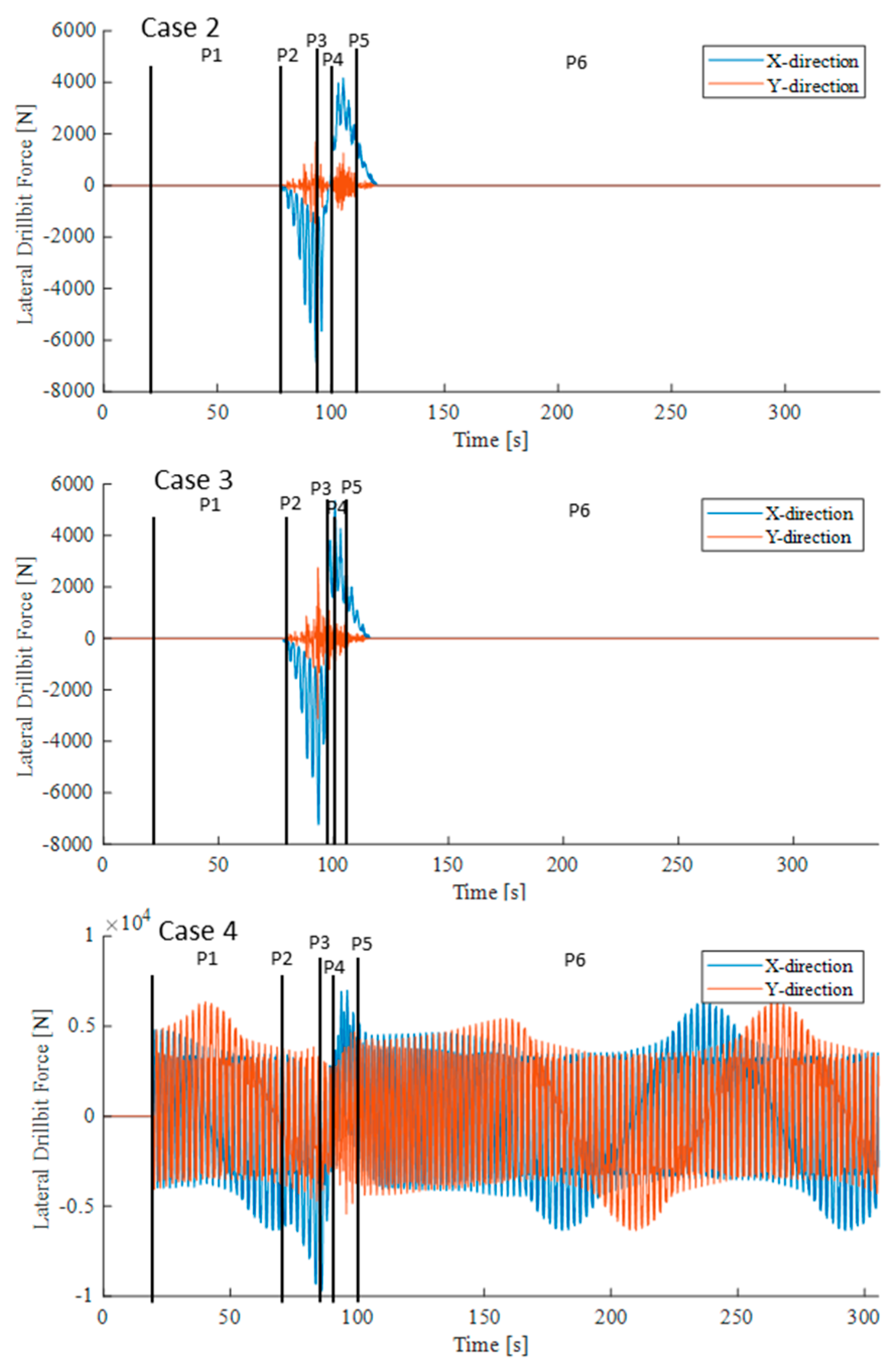
Figure 17, on the other hand, focuses on the lateral vibration behaviour of the bit when drilling through the sandwich formation of Figure 12. A clearance of 0.005 m is set.
Figure 17.
Time simulation of the lateral oscillation and forces at the bit when drilling through formations of Figure 12.
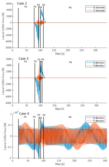
In cases 2 and 3, lateral forces can be seen at the bit level after ~80 s of simulation time due to formation inhomogeneity. In case 4 these forces are to be seen throughout the simulation time due to the asymmetric design of the bit. While these forces are periodic when drilling in a single rock, they are perturbed by inhomogeneities. Comparing cases 2 and 3, it is clear that the stiffness of the formation does not have much influence on the overall lateral vibration behaviour. However, in case 3, where the middle formation is too soft, a shock in the axial transition from rock 1 to rock 2 and then back to rock 1 leads to higher lateral forces, higher frequency of the lateral vibration and longer time to decay.
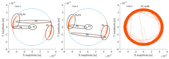
Figure 18 illustrates the orbital oscillations of the bit within the defined clearance (blue circle). In cases 2 and 3 we can clearly see the effect of the inhomogeneities in pushing the drill bit towards the hole. This effect depends on whether the drill bit is running from hard to soft rock (see P2, P3) or otherwise (see P5). In a homogeneous formation, the drill bit is laterally stable (see P1, P4, P6). In case 4, the drill bit is in forward whirling throughout the whole simulation. Thus, when using a symmetrical drill bit (cases 2 and 3), the drill bit is stable when drilling through homogeneous rock. However, when drilling through inhomogeneities, the drill bit will rotate around its own axis while being pushed towards the same point of the hole. This can cause malicious lateral vibrations, such as backward whirl, which can cause tremendous damage. On the other hand, an asymmetric drill bit (case 4) will have a continuous forward whirl in both homogeneous and inhomogeneous formations. However, the forward whirl makes the bit more stable against backward whirl.
Figure 18.
Orbit oscillations of the drill string in different positions.
5. Conclusions
The core of this work is the developed mesoscopic drill bit model, which has been introduced and described in detail. This model can be used to simulate and analyse drill string vibrations when drilling through inhomogeneous rock formations with symmetrical and asymmetrical drill bits. For this task, the new drill bit model has been coupled with an existing drill string model, OSPLAC, which is also explicitly presented here. This allows extensive simulation studies to be carried out for drilling through inhomogeneous rock zones with different bit types, including anti-whirl bits. To this end, the operation of the mesoscopic bit model and drilling through a sandwich formation were simulated in four case studies. The resulting torsional and lateral vibrations were presented and discussed as a function of the formation drilled and the type of bit used. These first simulation studies show the influence of drilling through rock inhomogeneities with different drill bits on the torsional and lateral vibration behaviour.
In future research, it will be important to investigate the sensitivity of individual parameters in more detail through comprehensive simulation studies. For example, the influence of the number of cutting blades and their geometric configuration on the bit and its clearance, or of course the formation parameters such as Young’s modulus, inclination, etc. on the bit and drill string dynamics need to be investigated in more detail. A validation of the simulation results with measurements would be the next obvious step, but this requires collaborative projects with drilling companies and drilling service companies on this topic. In addition, the model should be used to investigate in detail the deviations of the drill string when drilling through rock inhomogeneities.
Author Contributions
Conceptualisation, G.-P.O. and F.S.; methodology, G.-P.O.; software, M.I.; formal analysis, M.I.; investigation, M.I.; resources, G.-P.O.; data curation, M.I. and F.S.; writing—original draft preparation, M.I. and F.S.; writing—review and editing, G.-P.O. and F.S.; visualisation, M.I. and F.S.; supervision, G.-P.O. and F.S.; project administration, G.-P.O. and F.S.; funding acquisition, G.-P.O. All authors have read and agreed to the published version of the manuscript.
Funding
We acknowledge support by the Open Access Publication Funds of the Technische Universität Braunschweig.
Data Availability Statement
The data obtained in this study are available upon reasonable request.
Acknowledgments
The authors would like to thank the German Federal Ministry of Economics and Energy (BMWi) for funding the research work within the collaborative project “OBS–Optimization of the Rate of Penetration for Deep Geothermal Wells through Systematic Analysis of Downhole Vibrations in Lab Tests” (FKZ: 0324115B). This project is overseen by Projektträger Jülich (PtJ).
Conflicts of Interest
The authors declare no conflict of interest.
Nomenclature
| Symbol | Definition | Unit |
| A | Area | m2 |
| Characterising points of blade i of the drill bit | - | |
| Lever arm of the drill bit | m | |
| Rock damping | Ns/m | |
| Damping matrix | Ns, Nms/rad | |
| Drill bit diameter | m | |
| Young’s elasticity modulus | N/m2 | |
| Drill string attached coordinate system | ||
| Force vector | N | |
| Penetration depth, velocity | m, m/s | |
| Resulting cutting force at the bit | N | |
| Cutting force per length | N/m | |
| Cutting force on front side | N | |
| Distributed force per length | N | |
| Normal force | N | |
| Friction/resistance force | N | |
| Cutting force on shoulder | N | |
| Shear modulus | N/m2 | |
| Moment of inertia | m4 | |
| Inertial coordinate system at drilling tower | ||
| Inertial coordinate vectors showing north, east and Earth directions, respectively | ||
| Point of intersection between rock 1 and 2 on blade i | ||
| Polar moment of inertia | m4 | |
| Rock stiffness | N/m | |
| Stiffness matrix | N/m, Nm/rad | |
| L | Drill string length | m |
| BHA length | m | |
| of blade i | m | |
| of blade i | m | |
| Sum of lengths of all cutting blades | m | |
| Shoulder length of blade i | m | |
| Inertia matrix | kg, kgm2 | |
| Cutting torque on front side of the drill bit | Nm | |
| Friction/resistance torque | Nm | |
| Cutting torque on shoulder | Nm | |
| Torsional torque | Nm | |
| Number of blades of the drill bit | - | |
| P | Centrepoint of the drill bit | - |
| P1, P2, P3, P4, P5, P6 | Six positions of the drill bit in contact with formations 1 and 2 | - |
| of each blade and the bit centre P | m | |
| Borehole radius | m | |
| Darboux matrix | 1/m, rad/m | |
| Drill string outer radius | m | |
| Total rotation matrix | - | |
| Drilling trajectory | m | |
| - | ||
| Kinetic energy | Nm | |
| Acceleration, velocity, deformation | m/s2, m/s, m | |
| Local coordinates at element i | - | |
| Relative contact speed | m/s | |
| W | Work of force | Nm |
| Translation degrees of freedom | m | |
| Inclination angle | rad | |
| Shoulder angle | rad | |
| Azimuth angle | rad | |
| Clearance | m | |
| Strain | - | |
| Curvature | 1/m | |
| Friction/resistance coefficient | - | |
| Deformation energy | Nm | |
| Twisting | rad/m | |
| Rotation degrees of freedom | rad | |
| Whirl angle, velocity | rad, rad/s |
References
- Bellin, F.; Dourfaye, A.; King, W.; Thigpen, M. The current state of PDC bit technology. World Oil 2010, 231, 67–71. [Google Scholar]
- Lake, W.L. Petroleum Engeneering Handbook; Society of Petroleum Engineering: Richardson, TX, USA, 2006. [Google Scholar]
- Reckmann, H.; Meyer-Heye, B.; Herbig, C. Steps and Methods to Drive Reliability and Performance of Drilling Systems. Oil Gas Eur. Mag. 2015, 41, 26–27. [Google Scholar]
- Ostermeyer, G.-P.; Schiefer, F.; Ichaoui, M. Stick-Slip Processes on Drill Strings in Simulation and Application. Oil Gas Eur. Mag. 2019, 45, 15–16. [Google Scholar]
- Leine, R.I.; Van Campen, D.H.; Keultjes, W.J.G. Stick-slip Whirl Interaction in Drillstring Dynamics. J. Vib. Acoust. 2002, 124, 209–220. [Google Scholar] [CrossRef] [Scilit]
- Jain, J.R.; Oueslati, H.; Hohl, A.; Reckmann, H.; Ledgerwood, L.W.; Tergeist, M.; Ostermeyer, G.P. High Frequency Torsional Dynamics of Drilling Systems: An Analysis of the Bit-System Interaction. In Proceedings of the IADC/SPE Drilling Conference and Exhibition, Fort Worth, TX, USA, 4–6 March 2014; Society of Petroleum Engineers: Kuala Lumpur, Malaysia, 2014. [Google Scholar]
- Hohl, A.; Tergeist, M.; Oueslati, H.; Jain, J.R.; Herbig, C.; Ostermeyer, G.P.; Reckmann, H. Derivation and experimental validation of an analytical criterion for the identification of self-excited modes in drilling systems. J. Sound Vib. 2015, 342, 290–302. [Google Scholar] [CrossRef] [Scilit]
- Kulke, V.; Ostermeyer, G.P.; Tergeist, M.; Hohl, A. Semi-Analytical Approach for Derivation of an Equivalent Modal Friction-Damping Ratio and its Application in a Self-Excited Drilling System. In Proceedings of the ASME International Mechanical Engineering Congress and Exposition, Salt Lake City, UT, USA, 11–14 November 2019; American Society of Mechanical Engineers: New York, NY, USA, 2019; Volume 59414, p. V004T05A080. [Google Scholar]
- Hohl, A.; Kulke, V.; Kueck, A.; Herbig, C.; Reckmann, H.; Ostermeyer, G.P. The Nature of the Interaction Between Stick/Slip and High-Frequency Torsional Oscillations. In Proceedings of the IADC/SPE International Drilling Conference and Exhibition, Galveston, TX, USA, 3–5 March 2020; Society of Petroleum Engineers: Kuala Lumpur, Malaysia, 2020. [Google Scholar]
- Kück, A. Zur Eceriferum von Minimalmodellen für die Dynamik von Tiefbohrsträngen. Ph.D. Thesis, Technische Universität Braunschweig, Braunschweig, Germany, 2019. [Google Scholar]
- Jansen, J.D. Nonlinear Dynamics of Oilwell Drillstrings. Ph.D. Thesis, TU Delft, Delft University of Technology, Delft, The Netherlands, 1993. [Google Scholar]
- Mihajlovic, N. Torsional and Lateral Vibrations in Flexible Rotor Systems with Friction. Ph.D. Thesis, Technische Universiteit Eindhoven, Eindhoven, The Netherlands, 2005. [Google Scholar]
- Christoforou, A.P.; Yigit, A.S. Fully coupled vibrations of actively controlled drillstrings. J. Sound Vib. 2003, 267, 1029–1045. [Google Scholar] [CrossRef] [Scilit]
- Moore, B.C. Principal component analysis in linear systems: Controllability, observability, and model reduction. IEEE Trans. Autom. Control 1981, 26, 17–32. [Google Scholar] [CrossRef] [Scilit]
- Jansen, J. Non-linear rotor dynamics as applied to oil well drillstring vibrations. J. Sound Vib. 1991, 147, 115–135. [Google Scholar] [CrossRef] [Scilit]
- Kueck, A.; Recke, B.; Ostermeyer, G.-P. Reduction of non-linear drill string models using proper orthogonal decomposition. Proc. Appl. Math. Mech. 2014, 14, 205–206. [Google Scholar] [CrossRef] [Scilit]
- Kueck, A.; Hohl, A.; Reckmann, H.; Ostermeyer, G.P. Automated Generation of Minimal Models for Drill String Dynamics. Oil Gas Eur. Mag. 2016, 42, 41–43. [Google Scholar]
- Kust, O. Selbsterregte Drehschwingungen in Schlanken Torsionsstäben, Nichtlineare Dynamik and Regelung. Ph.D. Thesis, VDI, Düsseldorf, Germany, 1998. [Google Scholar]
- Struck, H. Modellierung, Simulation and aktive Dämpfung selbsterregter Schwingungen eines gekrümmten Torsionsstranges. Ph.D. Thesis, Shaker, Aachen, Germany, 2004. [Google Scholar]
- Ostermeyer, G.P.; Brommundt, E. Theorie-Manual zum Programm OSPLAC: Optimal Stabilizer Placement Version 2.0; TU Braunschweig: Braunschweig, Germany, 1989. [Google Scholar]
- Shi, M. Ein Beitrag zur Modellierung and Simulation der Dynamik von Tiefbohrsträngen. Ph.D. Thesis, TU Braunschweig, Braunschweig, Germany, 2016. [Google Scholar]
- Kyllingstad, A.; Halsey, G.W. A Study of Slip-stick Motion of the Bit. SPE Annual Technical Conference and Exhibition. In Proceedings of the SPE Annual Technical Conference and Exhibition, Dallas, TX, USA, 27–30 September 1987; Society of Petroleum Engineers: Kuala Lumpur, Malaysia, 1987. [Google Scholar]
- Brett, J.F.M. The genesis of bit-induced torsional drillstring vibrations. SPE Drill. Eng. 1992, 7, 168–174. [Google Scholar] [CrossRef] [Scilit]
- Pessier, R.C.; Fear, M.J. Quantifying Common Drilling Problems with Mechanical Specific Energy and a Bit-Specific Coefficient of Sliding Friction. In Proceedings of the SPE Annual Technical Conference and Exhibition, Washington, DC, USA, 4–7 October 1992. [Google Scholar]
- Detournay, E.; Defourny, P. A phenomenological model of the drilling action of drag bits. Int. J. Rock Mech. Min. Sci. Geomech. 1992, 29, 13–23. [Google Scholar] [CrossRef] [Scilit]
- Richard, T. Determination of Rock Strength from Cutting Tests. Ph.D. Thesis, University of Minnesota, Twin Cities, MN, USA, 1999. [Google Scholar]
- Tergeist, M. Partikelmethoden zur Modellierung der Kontakte von Bohrstrang and Gestein beim Tiefbohren. Ph.D. Dissertation, TU Braunschweig, Braunschweig, Germany, 2019. [Google Scholar]
- Fu, Z.; Tergeist, M.; Kueck, A.; Ostermeyer, G.P. Investigation of the cutting force response to a PDC cutter in rock using the discrete element method. J. Pet. Sci. Eng. 2022, 213, 110330. [Google Scholar] [CrossRef] [Scilit]
- Fu, Z.; Ostermeyer, G.P.; Kueck, A.; Schiefer, F.; Reckmann, H.; Huang, X.; Bomidi, J. Modeling and Investigation of the Velocity-Dependent Cutting Process with PDC Cutters Using the Discrete Element Method. Shock Vib. 2023, 2023, 6381319. [Google Scholar] [CrossRef] [Scilit]
- Heisig, G. Zum Statischen and Dynamischen Verhalten von Tiefbohrsträngen in Räumlich Gekrümmten Bohrlöchern. Ph.D. Thesis, Mechanik Zentrum, TU Braunschweig, Braunschweig, Germany, 1993. [Google Scholar]
- Langeveld, C.J. PDC Bit Dynamics. In Proceedings of the IADC/SPE Drilling Conference, New Orleans, LA, USA, 18–21 February 1992. [Google Scholar]
- Meyer-Heye, B. Zum Einfluss von Räumwerkzeugen auf die Dynamik von Tiefbohrsträngen. Ph.D. Thesis, Technische Universität Braunschweig, Braunschweig, Germany, 2011. [Google Scholar]
- Henrichfreise, H. Zur Modellierung des Antriebes für ein Elastisches Handhabungs-System; DFG-Forschungsbericht LU 299/1–2, IR-Regelung/Hardware; Universität-GH Paderborn, Automatisierungstechnik: Paderborn, Germany, 1984. [Google Scholar]


Disclaimer/Publisher’s Note: The statements, opinions and data contained in all publications are solely those of the individual author(s) and contributor(s) and not of MDPI and/or the editor(s). MDPI and/or the editor(s) disclaim responsibility for any injury to people or property resulting from any ideas, methods, instructions or products referred to in the content. |
© 2023 by the authors. Licensee MDPI, Basel, Switzerland. This article is an open access article distributed under the terms and conditions of the Creative Commons Attribution (CC BY) license (https://creativecommons.org/licenses/by/4.0/).