1. Introduction
The significance of the modern greenhouse agricultural sector has been increasing in recent years owing to the growth of the global population and the increasing demand for food [
1,
2]. Greenhouse farming enables the year-round production of crops by avoiding extreme weather conditions [
3]. Maintaining a suitable environmental climate is essential for supporting plant growth and productivity in greenhouse farming. Extensive research has been conducted on cooling systems, including natural ventilation, forced ventilation, evaporative cooling, and combined cooling systems [
4,
5,
6,
7,
8]. These systems control the air temperature throughout the whole greenhouse farming area. Low air temperatures can be obtained in tropical regions with intensive cooling systems, such as air-conditioning systems; however, these systems require a considerable amount of energy to create a suitable environment for crops [
9].
Heat-sensitive crops such as strawberries require an air temperature between 20 and 28 °C during the day and 5 to 12 °C at night, which presents a major drawback for their cultivation in tropical regions [
10]. There is limited research on local cooling climate control, which focuses only near the plants using various heat exchanger diameters. Therefore, the novelty of this study involves local cooling climate control near to the crops for greenhouse farming, with the aim of reducing energy consumption.
Salman et al. [
11] examined the possibility of constructing solar photovoltaic panels on the roofs of greenhouses under Iraqi climate conditions. In their study, the solar panels’ shade can lower temperatures by 5 to 10 °C depending on the arrangement of the panels. This reduction is particularly beneficial on hot days because it prevents overheating of crops. They investigated solar panels incorporated into greenhouse farming for energy supply.
In addition, heat exchangers are widely utilized in various industrial applications such as power plants, heating, ventilation, and air-conditioning systems [
12,
13,
14,
15,
16]. In greenhouse crop cultivation, earth-to-air heat exchangers are one of the methods to provide the environmental control for crops [
17,
18,
19,
20]. The earth-to-air heat exchangers use underground pipes under a certain depth of soil and carry indoor or outdoor air into the pipes. The temperature difference between the soil and air can be applied to substitute the heated or cooled air in the greenhouse. In this way, the earth-to-air heat exchanger system provides air temperature control in the greenhouse.
Hasan et al. [
21] used numerical simulation on the earth-to-air heat exchanger system, analyzing the impact of design parameters, such as pipe diameter and length, on performance in Nasiriyah, Iraq. Morshed et al. [
22] assessed the impact of pipe length, diameter, and airflow velocity of an earth-to-air heat exchanger on its heat transfer performance in agricultural greenhouses in a Mediterranean climate. Wang et al. [
23] developed a mathematical model to predict the cooling capacity of earth-to-air heat exchangers, considering tube diameter, tube length, air velocity, and the inlet air and the undisturbed soil temperature difference in livestock buildings. Qi et al. [
24] analyzed the uniformity and thermal performance of the multi-pipe earth-to-air heat exchanger with a variation in the diameter ratio of heat exchanger. These studies found that pipe diameter impacts the thermal performance of the earth-to-air heat exchanger.
In several studies, an environmental control system is used to control the air temperature in the whole greenhouse area. Thus, a research gap exists in developing suitable heat exchanger configurations for local cooling in smart greenhouse farming. Few studies have investigated the performance of serpentine heat exchangers of local cooling systems by considering the effect of pipe diameter. The pipe diameter of heat exchanger strongly influences the pressure drop, flow rate, and heat transfer surface area of the heat exchanger.
Therefore, this study aims to investigate the characteristics of the local air temperature as well as the heat transfer of serpentine copper pipe heat exchangers with different diameters. In particular, the performance of the unit-element heat exchanger is highlighted in this study. The concept of the proposed local cooling climate method is to create a suitable environment only near the crops. Moreover, the study results would be useful in suggesting a suitable configuration of the heat exchanger for growing crops inside greenhouses.
2. Materials and Methods
2.1. Experimental Setup
The copper pipes were arranged in a serpentine configuration and used as heat exchangers in the local cooling control method. The serpentine configuration allows light for crop growth and the easy maintenance of humid areas like agricultural fields.
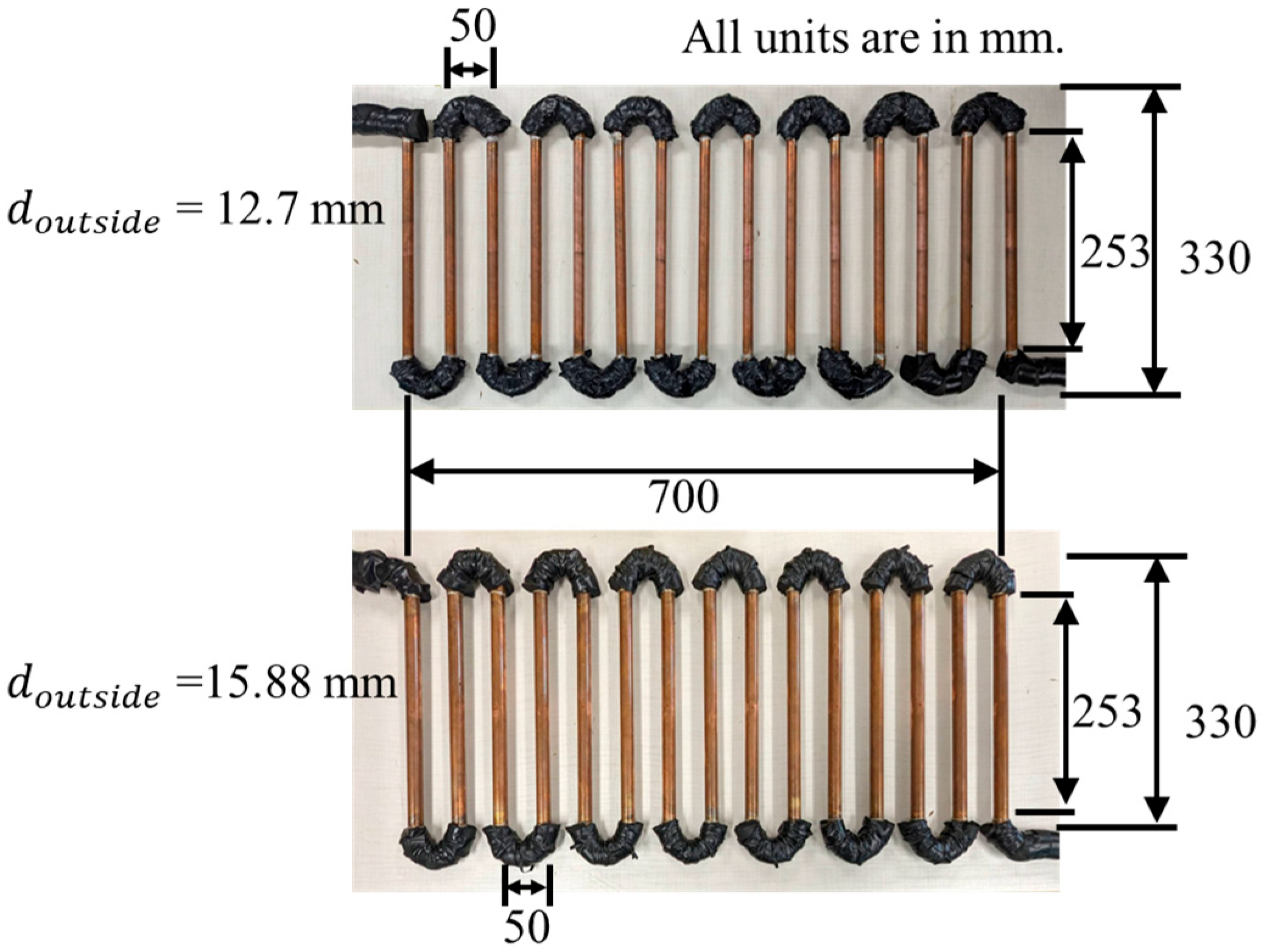
Figure 1 depicts the configuration of the serpentine copper pipe heat exchangers with a width and length of 700 mm and 253 mm, respectively, except for the bend areas. The thickness of the copper pipes is 0.8 mm. Each pipe is assembled in a U-bend, and these U-bends are insulated to evaluate the exact heat transfer from the straight pipe surfaces. The pipe spacing of each copper pipe is 50 mm. The number of pipes is 15 for each heat exchanger. Type 1 (
= 12.7 mm) and 2 (
= 15.88 mm) heat exchangers with the same pitch were tested. The pipe surface area of the Type 1 heat exchanger is 0.151 m
2 while that of the Type 2 heat exchanger is 0.189 m
2. The inside diameters of each heat exchanger can be obtained by subtracting twice the pipe wall thickness from the outer diameter. The dimensions of heat exchangers can cover one small rectangular block of the plantation in greenhouse farming. Additionally, these copper pipes’ diameters are chosen because they are standard size in the market and would be suitable for providing the plants with low shade.
The experiments were conducted by changing the pipe diameter of the heat exchanger in the same test section area. An insulation panel was placed to separate the experimental setup and the room. Strawberry plants typically require daytime and nighttime temperature ranges of 20–28 °C and 5–12 °C for optimal growth. In tropical climate regions, the weather is usually warm even in the cold season. Strawberries are considered heat-sensitive crops due to their vulnerability to very high temperatures. Therefore, in this study, we consider strawberry crops for greenhouse farming, and a heat exchanger is installed above the plants for local cooling
The experimental system was set up assuming no crops were present.
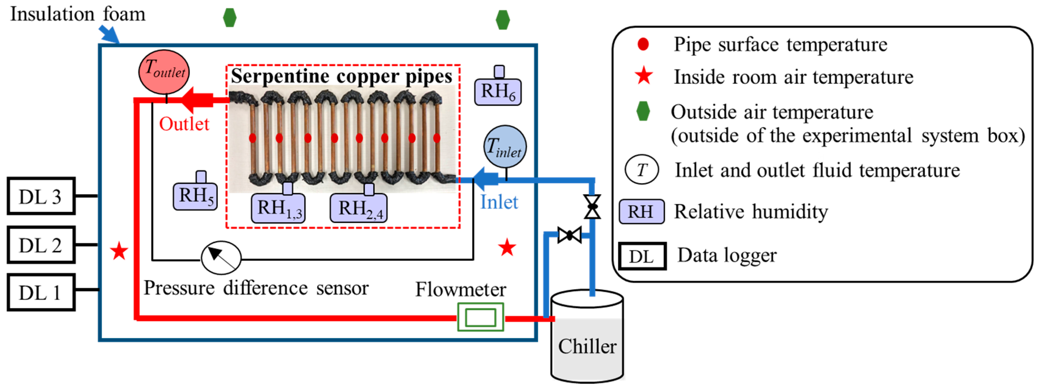
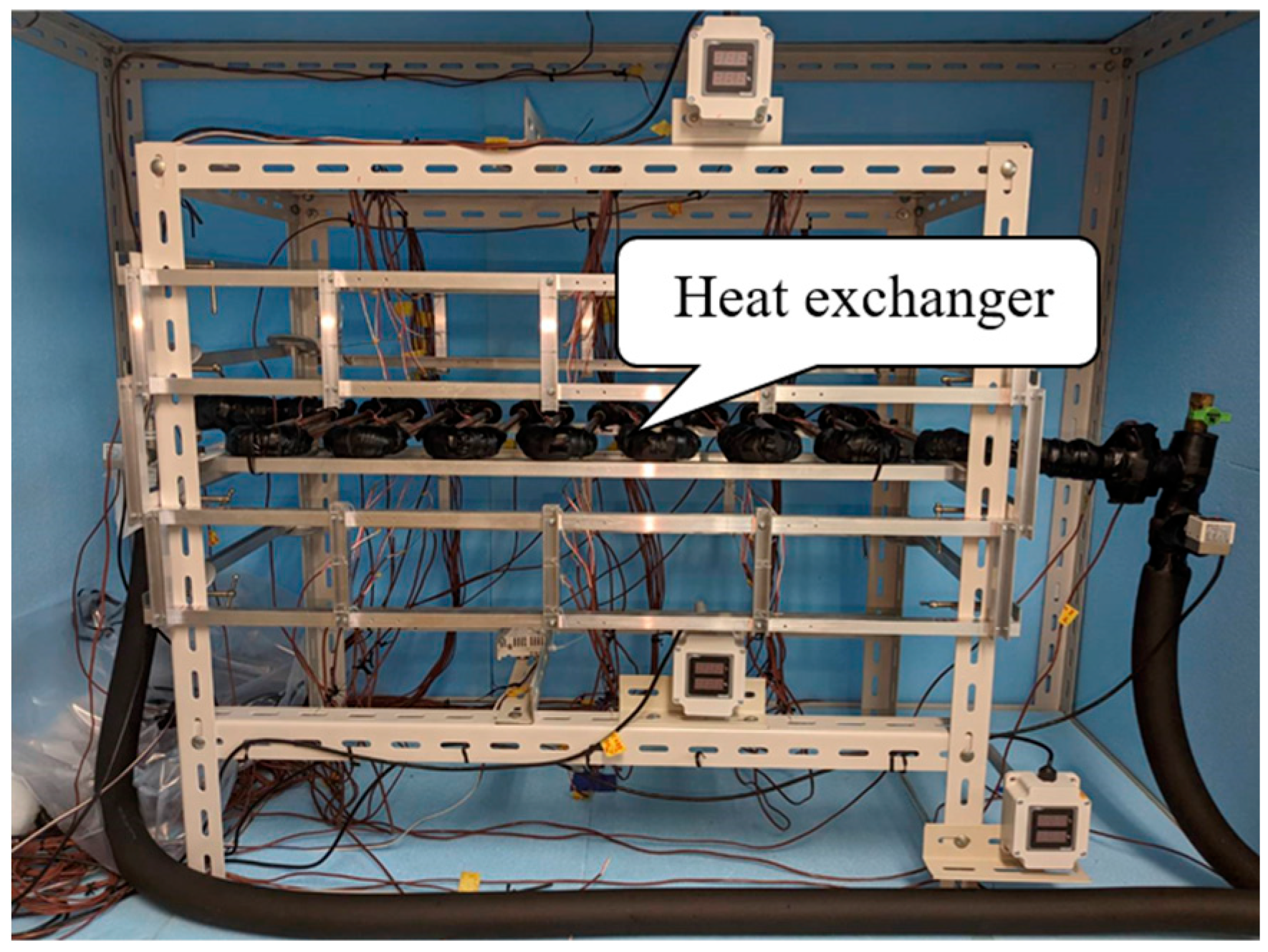
Figure 2 presents an overview of the experimental system. The experimental area is 1.4 m in width, 0.7 m in depth, and 1.0 m in height.
2.2. Data Accumulation
The air temperatures in the area below and above the heat exchanger were measured to analyze the local air temperature profiles. We focused on the area below the heat exchanger, and the area above it was used as a reference.
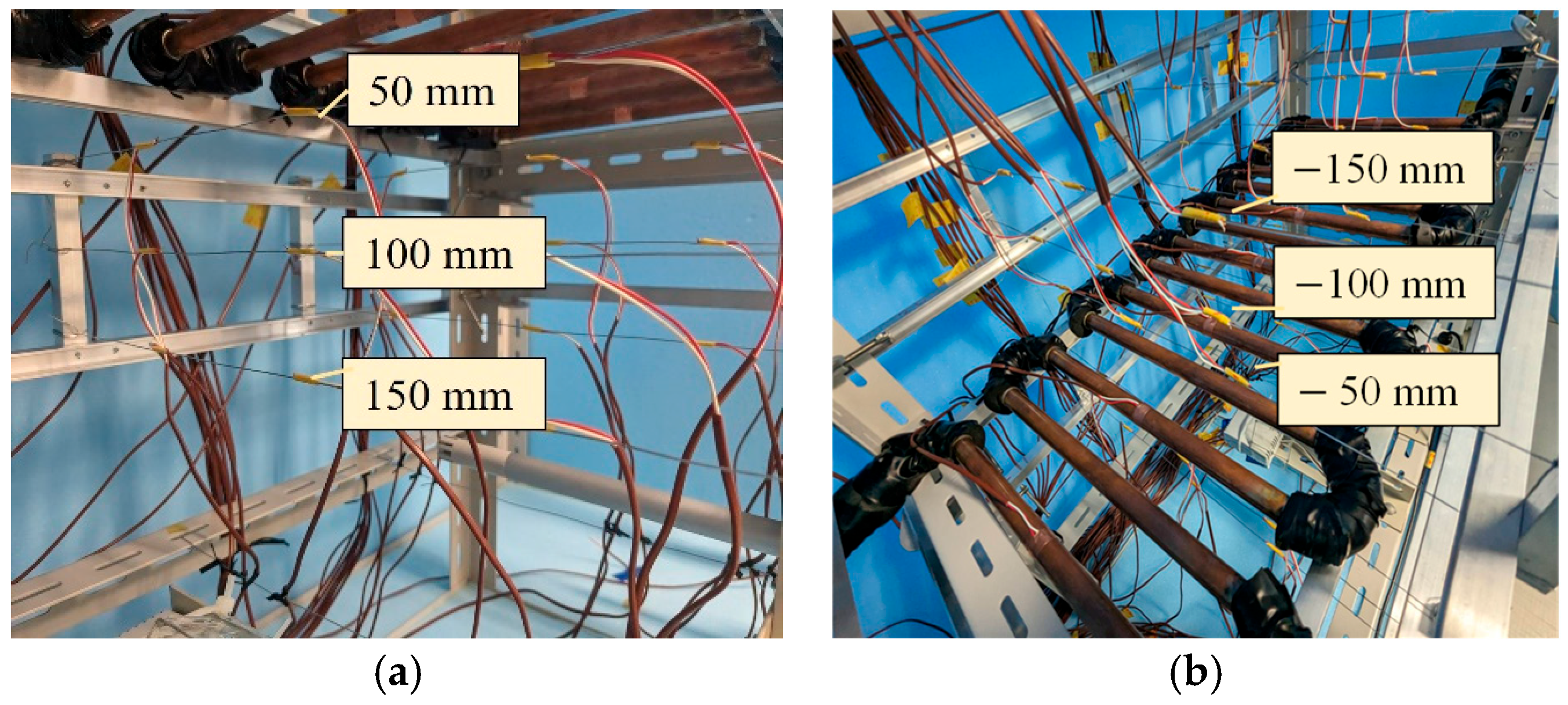
Figure 3 depicts the vertical air temperature measurements around the heat exchanger. There were three horizontal layers below and above the heat exchanger. The layers below the heat exchanger were located 50 mm, 100 mm, and 150 mm from the center of the heat exchanger, as shown in
Figure 3a. The layer distance in the area below was assigned a (+) sign following the natural convection and gravitational force. The above layers are symmetrical to those below, and were −50 mm, −100 mm, and −150 mm away from the center of the heat exchanger, as shown in
Figure 3b. There were nine thermocouples in each horizontal layer, resulting in 54 thermocouples in the six layers. Furthermore, the vertical uncertainty of the thermocouple’s positions in each horizontal layer was ±2 mm.
Figure 4 depicts the configuration of the experimental setup. The system included a serpentine heat exchanger, globe valves to control the fluid flow rates, a chiller to provide cooling, thermocouples for measuring surface, inside room air, outside air, and local air temperatures, resistance thermal detectors for monitoring inlet and outlet fluid temperatures, and a pressure difference sensor to measure the pressure drop of the heat exchanger. Humidity sensors were introduced for reference.
Experimental data were recorded using three data loggers. To reduce the temperature measurement inaccuracy, the temperature sensors were calibrated. The resistance thermal detectors were calibrated using a stable reference temperature under a static condition before the experimental period. The resistance thermal detectors have a measurement error of ±0.02 °C. The same procedure calibration was applied for T-type thermocouples. The reference thermocouple with the most stable temperature was carefully chosen. T-type thermocouples were calibrated with reference thermocouple. They have a measurement error of ±0.3 °C.
Table 1 summarizes the instruments utilized in the measurements. The sensor specifications were selected to ensure sufficient accuracy in data acquisition. Air temperatures were measured using T-type thermocouples, while resistance thermal detectors (Pt 100) were used to monitor the inlet and outlet fluid temperatures to determine the fluid temperature difference. Since the heat fluxes of the heat exchangers were calculated from the fluid temperature difference, resistance thermal detectors were chosen to provide reliable and precise measurements. A GC 50 differential pressure sensor was employed to quantify the pressure drop across the system, and the flow rate monitoring was performed.
2.3. Experimental Conditions
The inlet fluid temperature and fluid flow rate were varied in the different experimental conditions. The inlet fluid temperature ranged from −5 °C to 10 °C, whereas the fluid flow rate ranged from 0.3 to 3.0 L/min for both the heat exchangers, as can be seen in
Table 2. The Reynolds numbers ranged from 63 to 1394 and 50 to 1100 for pipe diameters of 12.7 mm and 15.88 mm, respectively. The experimental inlet fluid temperatures are sufficient to maintain appropriate air temperature range for the crop. Moreover, a flow rate below 3.0 L/min is adequate, as the local temperature reduction shows no significant variation at higher flow rates based on our prior research [
25]. A mixture of water (60% by volume) and ethylene glycol (40% by volume) was used as the operating fluid to lower the freezing point of water. The experimental data were collected at an outside air temperature of 25 °C.
The Reynolds number (
) is calculated as follows:
where
ρ denotes the fluid density (kg/m
3),
denotes the velocity of the fluid (m/s),
denotes the inner diameter of the copper pipe (m), and
denotes the fluid dynamic viscosity (Pa·s).
The heat transfer was determined from the data obtained under steady-state conditions, as follows:
where
represents the heat flux from the copper pipe surfaces (W/m
2),
represents the fluid flow rate (m
3/s),
represents the fluid specific heat [J/(kg·K)],
represents the outer surface area of the copper pipe without the U-bends (m
2), and
and
represent the inlet and outlet fluid temperatures (°C), respectively. It should be noted that 1 L/min = 1.6667
10
−5 m
3/s.
3. Results
In this study, the local air temperature indicates the air temperature close to the growing crops. The analysis of the heat flux within the heat exchanger was conducted using a fluid flow rate ranging from 0.3 to 1.3 L/min. The heat flux assessment of the fluid flow rate higher than 1.3 L/min was omitted due to the insufficient accuracy of the recorded fluid temperature difference, (=).
3.1. Local Air Temperature Profiles and Air Temperature Reduction
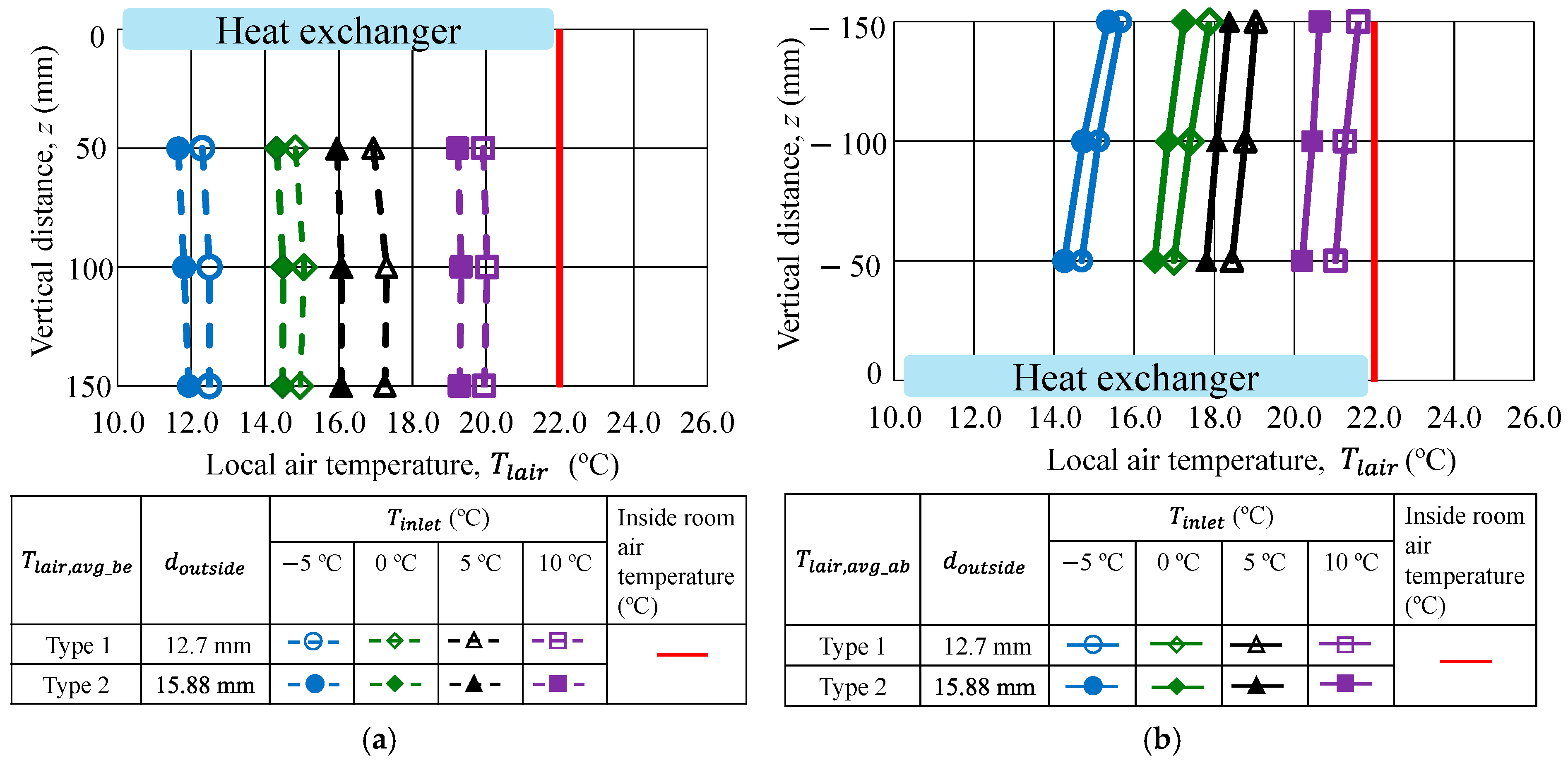
Figure 5 presents comparisons of the average local air temperature profiles at each vertical distance around the Type 1 and Type 2 serpentine copper pipe heat exchangers. The local air temperatures in each horizontal layer of the nine thermocouples were averaged.
Figure 5a,b present the average local air temperature profile of areas below and above the heat exchanger, respectively, at a fluid flow rate of
= 0.9 L/min as a reference for all the inlet fluid temperatures. The average local air temperatures of each layer in the area below and above the heat exchanger are denoted as
and
, respectively. The initial internal room air temperature is approximately 22 °C.
The
values of both the heat exchangers at each layer are approximately 12 °C, 15 °C, 17 °C, and 20 °C with inlet fluid temperatures of −5 °C, 0 °C, 5 °C, and 10 °C, respectively. According to
Figure 5b, the
values of both the heat exchangers range from 14 °C to 21 °C for the inlet fluid temperatures of −5 °C, 0 °C, 5 °C, and 10 °C. A comparison of
Figure 5a,b shows that
was lower than
for both types of heat exchangers. This is attributed to the buoyancy force that generates downward airflow. When the heat exchanger cools the surrounding air, a temperature gradient is established near the pipe surface. The air near the pipe surface becomes cool, and the cool air becomes denser. The dense air tends to sink. Thus, the air flows in a downward direction. Consequently, the air temperature of area below is cooler than the area above the heat exchanger. Therefore, the dominant heat transfer mechanism is via natural convection in this study.
It can be observed that the surrounding air temperature near both types of heat exchangers is decreased. This confirms that both the heat exchangers can provide effective cooling, particularly in the areas below them.
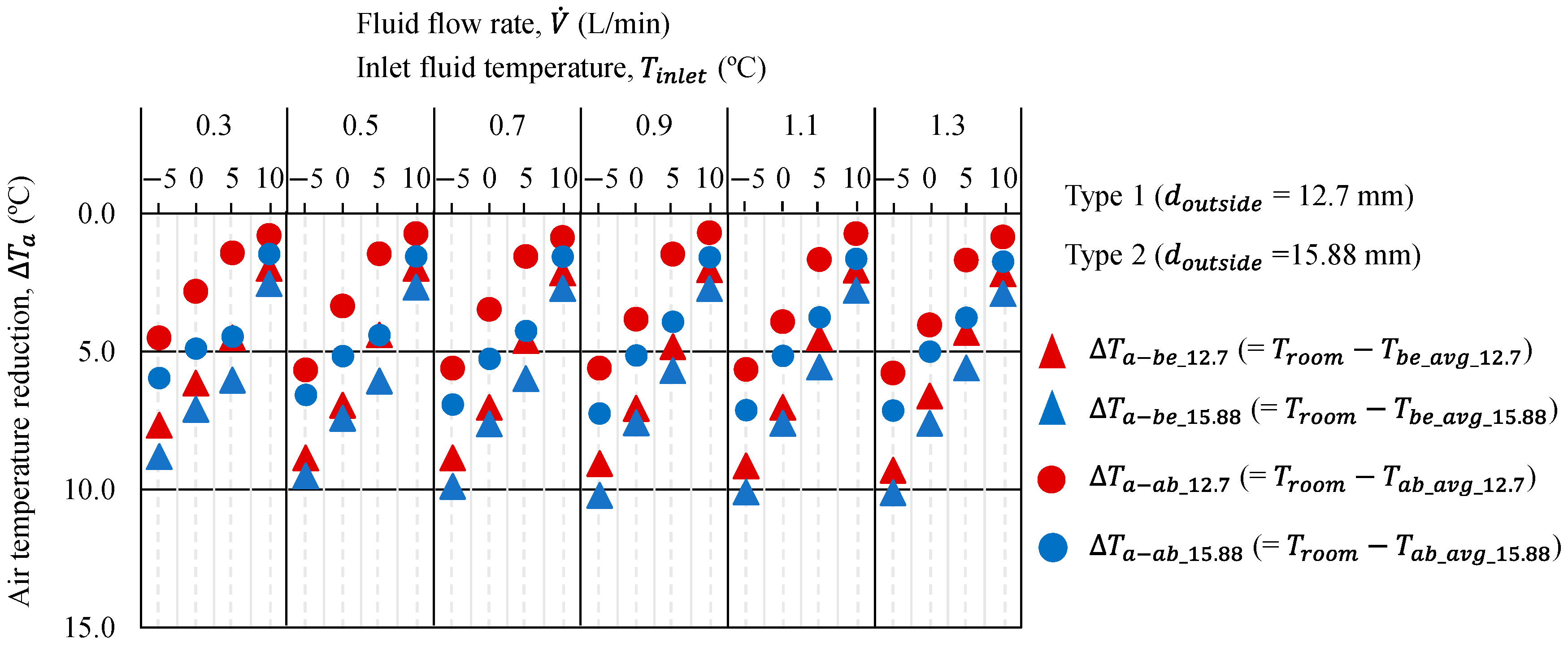
Figure 6 depicts the average local air temperature reduction in the inside room air temperature of the areas below and above the two types of heat exchangers under steady-state conditions for all the inlet fluid temperatures under fluid flow rates ranging from 0.3 L/min to 1.3 L/min. The local air temperatures of the three layers below and above were averaged. Subsequently, the average local air temperature reductions below and above the initial inside room air temperature were analyzed. At a fluid flow rate of 0.3 L/min and an inlet fluid temperature of −5 °C, the average local air temperature reductions, i.e., (
) and (
), are approximately 7.0 °C and 4.5 °C below and above the Type 1 heat exchanger, respectively. Conversely, in the case of the Type 2 heat exchanger,
and
are approximately 9.0 °C and 6.0 °C, respectively. At a fluid flow rate of 1.3 L/min and an inlet fluid temperature of −5 °C, both heat exchangers showed average local air temperature reduction (
,
) of approximately 10 °C in the area below.
As the inlet fluid temperature decreased, the local air temperature decreased from its initial value. Although the fluid flow rate increased, the average local air temperature reduction was insignificant after 0.7 L/min. It can be concluded that the local air temperature can be reduced, even with a low fluid flow rate. In addition, the inlet fluid temperature has a greater impact on the reduction in local air temperature than the fluid flow rate.
3.2. Pressure Drop
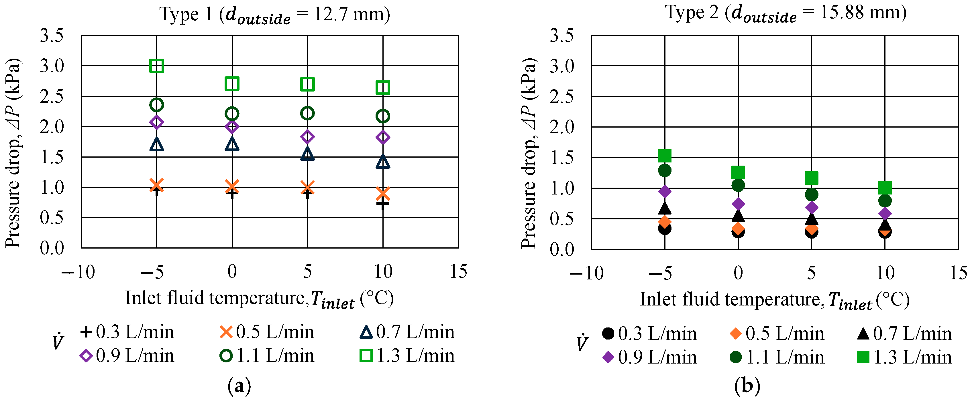
Figure 7 depicts the pressure drop in the two types of heat exchangers for fluid flow rates ranging from 0.3 to 1.3 L/min at all the inlet fluid temperatures.
Figure 7a,b present the pressure drops in the Type 1 and Type 2 heat exchangers, respectively. The pressure drop decreased as the inlet fluid temperature increased, as shown in
Figure 7. This is due to the decrease in the fluid viscosity when the inlet fluid temperature increases. However, the pressure drop increased when the fluid flow rate increased.
A comparison of
Figure 7a,b shows that the decrease in pressure drop is related to an increase in the diameter of the copper pipe. The pressure drop in the Type 2 heat exchanger is lower than that in the Type 1 heat exchanger as the pressure drop corresponds to the diameter of the copper pipe. The pressure drop ranges from 0.3 kPa to 3.0 kPa for both types of heat exchangers. The pressure drop in the Type 2 heat exchanger was approximately half of that in the Type 1 heat exchanger. Based on the experimental results, a Type 2 heat exchanger can be selected as it presented a lower pressure drop than the Type 1 heat exchanger.
3.3. Heat Flux in the Heat Exchanger
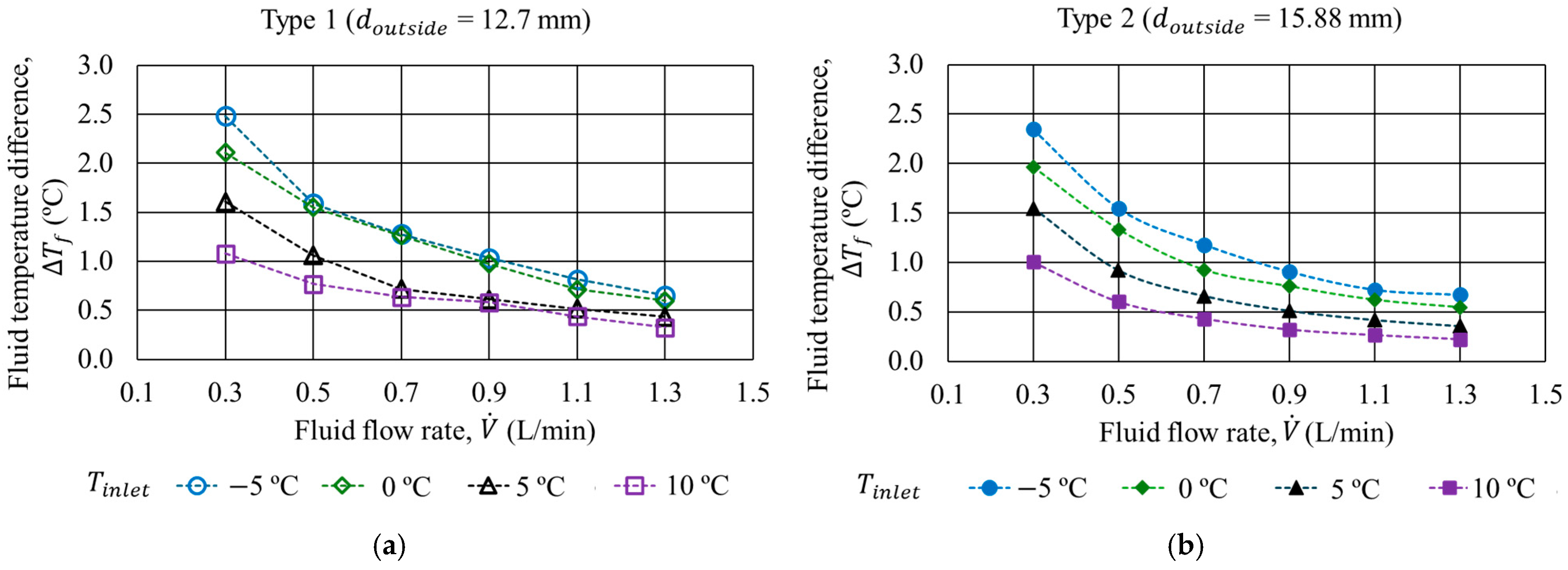
Figure 8 depicts the outlet and inlet fluid temperature difference,
, of both types of heat exchangers at all the inlet fluid temperatures under a fluid flow rate ranging from 0.3 L/min to 1.3 L/min.
Figure 8a,b present
in the Type 1 and Type 2 heat exchangers, respectively.
decreased markedly with the increase in the fluid flow rate. This indicates that
correlates to the fluid flow rate. Furthermore, the
values were almost identical for both types of heat exchangers for all the experimental conditions. At a low fluid flow rate of 0.3 L/min, the
value is higher than those at other fluid flow rates. This could be attributed to the longer contact time between the fluid and the pipe surface in the heat exchangers. The
values range from 2.5 °C to 0.2 °C for fluid flow rates from 0.3 L/min to 1.3 L/min at all the inlet fluid temperatures.
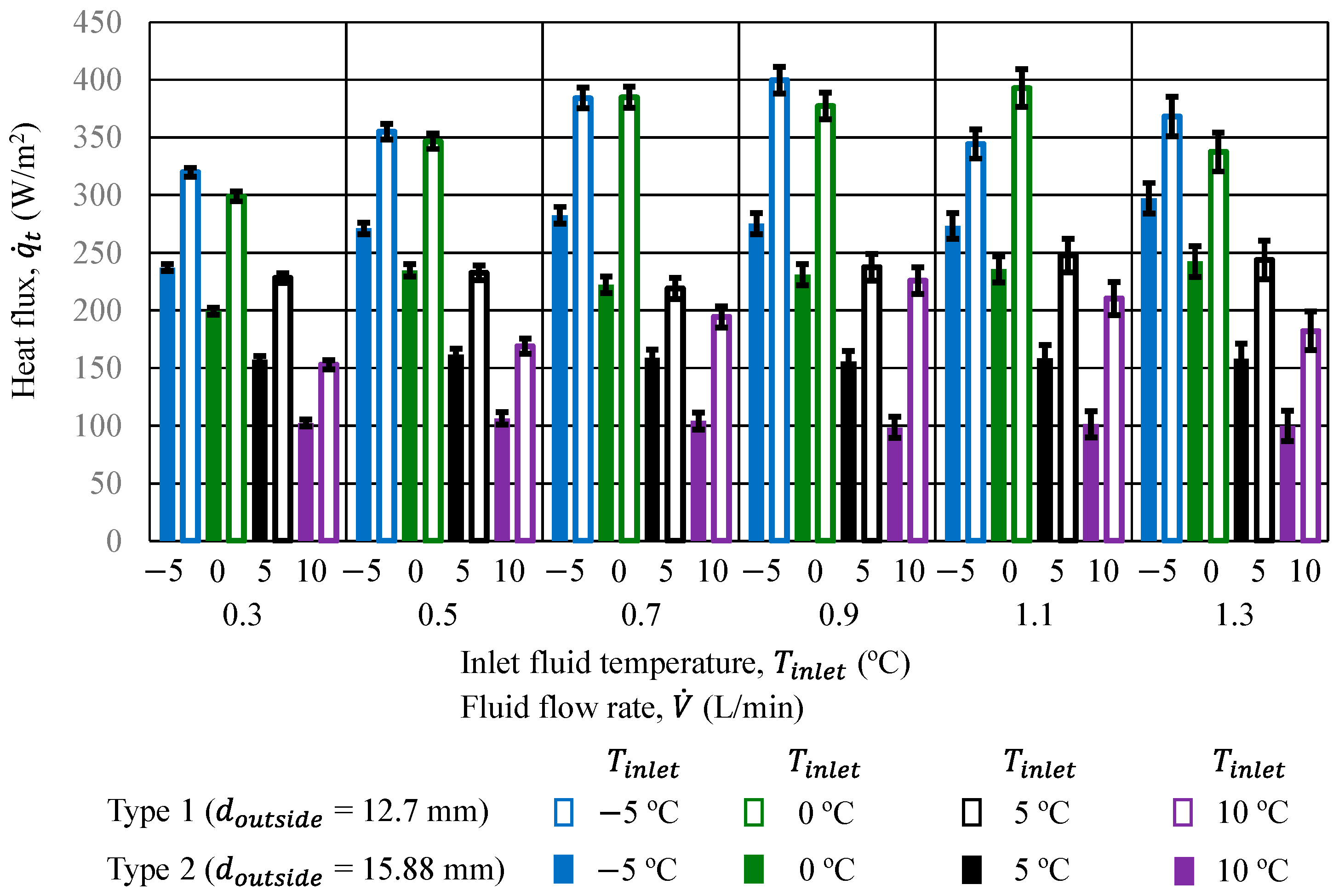
Figure 9 presents a comparison of the heat flux in the Type 1 and Type 2 heat exchangers. The heat flux,
, was calculated using Equation (2); it presents the relationship between
and the fluid flow rate.
exhibited 2–10% uncertainty for both the heat exchangers. In
Figure 9, the uncertainties are represented as error bars, which were estimated based on the measurement uncertainty of ±0.02 °C of the resistance thermal detectors. At a fluid flow rate of 0.3 L/min, for the Type 1 heat exchanger,
was approximately 330 W/m
2 at an inlet fluid temperature of −5 °C and the minimum
was approximately 150 W/m
2 at an inlet fluid temperature of 10 °C. Conversely, for Type 2 heat exchanger,
was about 250 W/m
2 and 100 W/m
2 at inlet fluid temperatures of −5 °C and 10 °C, respectively. The heat flux increased steadily with the fluid flow rate.
The average heat flux in the Type 1 heat exchanger was higher than that in the Type 2 heat exchanger. This is attributed to the thin thermal boundary layer and the higher fluid velocity of the Type 1 heat exchanger than the Type 2 heat exchanger at the same fluid flow rate. Consequently, the heat flux of the Type 1 heat exchanger was higher than that of the Type 2 heat exchanger.
4. Discussion
Several researchers have explored various cooling technologies to identify those that offer optimal climate control in greenhouse environments.
Table 3 elucidates the comparative analysis between the current study and prior related studies. To analyze and compare the cooling effect of the system from the current study and prior studies, the air temperature reduction provided by the systems is highlighted.
The current research focuses on the characteristics of local air temperature profiles of serpentine copper pipe heat exchangers for growing crops in greenhouses. It is evident from the study results that both types of heat exchangers can reduce the average local air temperature by approximately 10 °C from the initial room air temperature of 22 °C based on the experimental results. This indicates that the heat exchangers could adequately control the local air temperature near the crops. Thus, they could satisfy the temperature requirement of strawberry crops. Furthermore, the local air temperatures can be reduced even at low fluid flow rates. A lower fluid flow rate could potentially be adequate as the local air temperatures show insignificant change when the fluid flow rate exceeds 0.7 L/min.
The pressure drop in the Type 2 heat exchanger was approximately half of that in the Type 1 heat exchanger. This may decrease the required pumping power of the heat exchanger when Type 2 is chosen over Type 1. However, the larger pipe diameter of the Type 2 heat exchanger may have created more sunlight shadows on the plantation. The cost of a pipe of a larger diameter for Type 2 may be higher than that for Type 1.
As mentioned earlier, the earth-to-air heat exchangers use underground pipes under a certain soil depth and carry indoor or outdoor air into the pipes. Hasan et al. [
21] numerically studied the earth-to-air heat exchanger system with varying pipe diameters (2, 3, 4, and 6 inches) for a pipe of 50 m length and buried 3 m underground in summer and winter conditions in Nasiriyah, Iraq. The simulation results revealed that the air temperature in the building could be maintained at around 26.3 °C with a 2-inch pipe heat exchanger at a summer temperature of 40 °C. The temperature reduction would be approximately between 4 and 20 °C according to their results. Their results found that a 2-inch pipe exhibits better thermal performance than other pipes.
Wang et al. [
23] investigated the cooling performance of the earth-to-air heat exchanger by developing mathematical models that considered four factors. These factors included the pipe diameter (0.2, 0.4, and 0.6 m), pipe length (20, 40, and 60 m), air velocity (1, 3, and 5 m/s), and temperature difference between the inlet air and the undisturbed soil. Their modeling results showed that, when the pipe diameter was reduced, the air temperature difference between the pipe inlet and outlet could be 4.37 °C (where the inlet temperature is 45.9 °C). Their results also suggested that a smaller pipe diameter could improve the cooling performance of the heat exchanger. The above studies found that pipe diameter impacts the thermal performance of the earth-to-air heat exchanger.
Villagran et al. [
26] conducted simulations to assess how increasing the height of a Colombian multi-tunnel greenhouse influences airflow and thermal distribution. Their findings indicated that the greenhouse temperature decreased by 0.1 to 11.7 °C, depending on the ventilation setup and external wind conditions. This temperature reduction can be obtained for the average daytime temperature range of 23~30 °C.
Al-Mulla et al. [
27] examined polyethylene-tunnel greenhouses for cucumber cultivation. They experimentally evaluated the impact of evaporative cooling technologies on the greenhouse climate in Oman. Their findings revealed a greenhouse air temperature reduction of approximately 4.5° compared to the ambient outdoor temperature of around 31 °C.
5. Conclusions
In this study, the characteristics of local air temperature profiles of serpentine copper pipe heat exchangers with different diameters were analyzed to develop a suitable configuration for growing crops in greenhouse farming. The main finding of this study is that both types of heat exchangers can reduce the average local air temperature by approximately 10 °C from the initial room air temperature. From the study results, it can be concluded that both heat exchangers can provide effective cooling, particularly in the areas below them. This temperature reduction would be useful for strawberry crop cultivation.
Furthermore, the inlet fluid temperatures of the experiments are relevant for the practical applications of the proposed heat exchangers for greenhouse cultivation. Additionally, a fluid flow rate of 0.7 L/min appears adequate, as local air temperature reductions are minimal beyond this flow rate.
Experiments were conducted in the laboratory to evaluate the exact cooling performance of the unit element of the heat exchanger. A limitation of this study is the exclusion of the effects of solar radiation, ambient wind, and humidity, as this study was focused on the heat transfer performance. Hence, the effects of these parameters will be considered in future research. Moreover, the impact of diverse pipe spacing on the performance of the heat exchanger will be investigated in the future.
In practical greenhouse farming, multiple heat exchangers in series and parallel connections may be required; such a setup requires further validation in terms of flow distribution and cumulative pressure drop. In addition, the concept and methodology of local cooling considered in this study can be extended to further analyze local heating, which will be beneficial in cold-climate regions.
The potential advantage of this study is the reduction in the energy usage of unit-element heat exchangers for greenhouse farming due to air temperature control near the crop areas. Nevertheless, this advantage remains to be verified in future research. Therefore, in future work, the theoretical and numerical energy consumed by the heat exchangers in greenhouse farming will be analyzed and compared with that of traditional greenhouse farming.
Author Contributions
Conceptualization, T.S.W. and N.M.; methodology, T.S.W. and N.M.; validation, T.S.W. and N.M.; formal analysis, T.S.W. and N.M.; investigation, T.S.W. and N.M.; data curation, T.S.W. and N.M.; writing—original draft preparation, T.S.W.; writing—review and editing, N.M., N.W., C.C., S.E.-a. and M.H.; visualization, T.S.W.; supervision, N.M.; project administration, N.M.; funding acquisition, T.S.W. and N.M. All authors have read and agreed to the published version of the manuscript.
Funding
This research was funded by JST SPRING, Japan (Grant Number: JPMJSP2137), the Graduate School of Regional Innovation Studies and the Graduate School of Engineering, Mie University, Japan.
Institutional Review Board Statement
Not applicable.
Informed Consent Statement
Not applicable.
Data Availability Statement
Data are contained within the article.
Acknowledgments
The authors would like to express their gratitude to the Graduate School of Regional Innovation Studies and the Graduate School of Engineering, Mie University, Japan, for their experimental support.
Conflicts of Interest
The authors declare no conflicts of interest.
Nomenclature
The following nomenclature is used in this manuscript:
| outer surface area of the copper pipe (m2) |
| K)] |
| inner diameter of the copper pipe (m) |
| outer diameter of the copper pipe (m) |
| ∆P | pressure drop in the heat exchanger (kPa) |
| heat transfer from the copper pipe surfaces (W/m2) |
| Re | Reynolds number (dimensionless) |
| inlet fluid temperature (°C) |
| outlet fluid temperature (°C) |
| local air temperature (°C) |
| average local air temperature below the heat exchanger (°C) |
| average local air temperature above the heat exchanger (°C) |
| inside room air temperature (°C) |
| ) |
| air temperature reduction (°C) |
| fluid flow rate (L/min), (m3/s) |
| Greek symbols |
| density of the fluid (kg/m3) |
| velocity of the fluid (m/s) |
| s) |
| Subscripts | |
| a | air |
| ab | above |
| avg | average |
| be | below |
| f | fluid |
| lair | local air |
References
- Vermeulen, S.J.; Aggarwal, P.K.; Ainslie, A.; Angelone, C.; Campbell, B.M.; Challinor, A.J. Options for support to agriculture and food security under climate change. Environ. Sci. Policy 2012, 15, 136–144. [Google Scholar] [CrossRef] [Scilit]
- Chahidi, L.O.; Fossa, M.; Priarone, A.; Mechaqrane, A. Greenhouse cultivation in Mediterranean climate: Dynamic energy analysis and experimental validation. Therm. Sci. Eng. Prog. 2021, 26, 101102. [Google Scholar] [CrossRef] [Scilit]
- Sahdev, R.K.; Kumar, M.; Dhingra, A.K. A comprehensive review of greenhouse shapes and its applications. Front. Energy 2019, 13, 427–438. [Google Scholar] [CrossRef] [Scilit]
- Tawalbeh, M.; Aljaghoub, H.; Alami, A.H.; Olabi, A.G. Selection criteria of cooling technologies for sustainable greenhouses: A comprehensive review. Therm. Sci. Eng. Prog. 2023, 38, 101666. [Google Scholar] [CrossRef] [Scilit]
- Akrami, M.; Salah, A.H.; Javadi, A.A.; Fath, H.E.S.; Hassanein, M.J.; Farmani, R.; Dibaj, M.; Negm, A. Towards a sustainable greenhouse: Review of trends and emerging practices in analysing greenhouse ventilation requirements to sustain maximum agricultural yield. Sustainability 2020, 12, 2794. [Google Scholar] [CrossRef] [Scilit]
- Kolokotsa, D.; Saridakis, G.; Dalamagkidis, K.; Dolianitis, S.; Kaliakatsos, I. Development of an intelligent indoor environment and energy management system for greenhouses. Energy Convers. Manag. 2010, 51, 155–168. [Google Scholar] [CrossRef] [Scilit]
- Plessis, E.D.; Workneh, T.; Laing, M. Greenhouse cooling systems and models for arid climate. Sustain. Agric. Rev. 2015, 18, 181–215. [Google Scholar] [CrossRef] [Scilit]
- Soussi, M.; Chaibi, M.T.; Buchholz, M.; Saghrouni, Z. Comprehensive review on climate control and cooling systems in greenhouses under hot and arid conditions. Agronomy 2022, 12, 626. [Google Scholar] [CrossRef] [Scilit]
- Banakar, A.; Montazeri, M.; Ghobadian, B.; Pasdarshahri, H.; Kamrani, F. Energy analysis and assessing heating and cooling demands of closed greenhouse in Iran. Therm. Sci. Eng. Prog. 2021, 25, 101042. [Google Scholar] [CrossRef] [Scilit]
- Hancock, J.F. Strawberries, 2nd ed.; Crop Production Science in Horticulture Series; CABI: Wallingford, UK, 2021. [Google Scholar]
- Salman, H.D.; Ali, M.A.N.; Faraj, J.J. Study the possibility of using solar panels on the rooftop of plastic greenhouse for power generation during Iraqi climate. J. Adv. Res. Fluid Mech. Therm. Sci. 2020, 69, 91–110. [Google Scholar] [CrossRef] [Scilit]
- Cengel, Y.A.; Ghajar, A.J. Heat and Mass Transfer: Fundamentals and Applications, 5th ed.; McGraw-Hill Education: New York, NY, USA, 2020. [Google Scholar]
- Madhu, K.S.; Shankarareddy, R.; Sangashetty, S.G. Experimental study on the effect of TiO2–water nanofluid on heat transfer and pressure drop in heat exchanger with varying helical coil diameter. J. Adv. Res. Fluid Mech. Therm. Sci. 2023, 107, 50–67. [Google Scholar] [CrossRef] [Scilit]
- Chen, Q.; Xu, G.; Xia, P. The performance of a solar-driven spray flash evaporation desalination system enhanced by microencapsulated phase change material. Case Stud. Therm. Eng. 2021, 27, 101267. [Google Scholar] [CrossRef] [Scilit]
- Master, B.I.; Chunangad, K.S.; Boxma, A.J.; Kral, D.; Stehlík, P. Most frequently used heat exchangers from pioneering research to worldwide applications. Heat Transf. Eng. 2006, 27, 4–11. [Google Scholar] [CrossRef] [Scilit]
- Kabeel, A.E.; El-Said, E.M.S. A hybrid solar desalination system of air humidification, dehumidification and water flashing evaporation: Part II. Experimental investigation. Desalination 2014, 341, 50–60. [Google Scholar] [CrossRef] [Scilit]
- Xiao, J.; Wang, Q.; Wang, X.; Hu, Y.; Cao, Y.; Li, J. An earth–air heat exchanger integrated with a greenhouse in cold-winter and hot-summer regions of northern China: Modeling and experimental analysis. Appl. Therm. Eng. 2023, 232, 120939. [Google Scholar] [CrossRef] [Scilit]
- Hamdane, S.; Pires, L.C.C.; Silva, P.D.; Gaspar, P.D. Evaluating the thermal performance and environmental impact of agricultural greenhouses using earth-to-air heat exchanger: An experimental study. Appl. Sci. 2023, 13, 1119. [Google Scholar] [CrossRef] [Scilit]
- Zajch, A.; Gough, W.A. Seasonal sensitivity to atmospheric and ground surface temperature changes of an open earth–air heat exchanger in Canadian climates. Geothermics 2021, 89, 101914. [Google Scholar] [CrossRef] [Scilit]
- Bordoloi, N.; Sharma, A.; Nautiyal, H.; Goel, V. An intense review on the latest advancements of Earth air heat exchangers. Renew. Sustain. Energy Rev. 2018, 89, 261–280. [Google Scholar] [CrossRef] [Scilit]
- Hasan, M.I.; Noori, S.W.; Shkarah, A.J. Parametric study on the performance of the earth-to-air heat exchanger for cooling and heating applications. Heat Transf.—Asian Res. 2019, 48, 1805–1829. [Google Scholar] [CrossRef] [Scilit]
- Morshed, W.; Abbas, L.; Nazha, H. Heating performance of the PVC earth–air tubular heat exchanger applied to a greenhouse in the coastal area of west Syria: An experimental study. Therm. Sci. Eng. Prog. 2022, 27, 101000. [Google Scholar] [CrossRef] [Scilit]
- Wang, X.; Bjerg, B.S.; Zhang, G. Design-oriented modelling on cooling performance of the earth-air heat exchanger for livestock housing. Comput. Electron. Agric. 2018, 152, 51–58. [Google Scholar] [CrossRef] [Scilit]
- Qi, D.; Li, A.; Li, S.; Zhao, C. Comparative analysis of earth to air heat exchanger configurations based on uniformity and thermal performance. Appl. Therm. Eng. 2021, 183, 116152. [Google Scholar] [CrossRef] [Scilit]
- Wai, T.S.; Wongmongkol, N.; Chaichana, C.; Maruyama, N.; Hirota, M. Local air temperature profile around a serpentine pattern copper pipe heat exchanger for crop cultivation. AIP Conf. Proc. 2024, 3236, 080011. [Google Scholar] [CrossRef] [Scilit]
- Villagrán, E.; Flores-Velazquez, J.; Akrami, M.; Bojacá, C. Influence of the height in a Colombian multi-tunnel greenhouse on natural ventilation and thermal behavior: Modeling approach. Sustainability 2021, 13, 13631. [Google Scholar] [CrossRef] [Scilit]
- Al-Mulla, Y.A.; Al-Balushi, M.; Al-Busaidi, H.; Al-Mahdouri, A.; Kittas, C.; Katsoulas, N. Analysis of microclimate and cucumber fruit yield in a screenhouse and an evaporatively cooled greenhouse in a semi-arid location. Trans. ASABE 2018, 61, 619–629. [Google Scholar] [CrossRef] [Scilit]
| Disclaimer/Publisher’s Note: The statements, opinions and data contained in all publications are solely those of the individual author(s) and contributor(s) and not of MDPI and/or the editor(s). MDPI and/or the editor(s) disclaim responsibility for any injury to people or property resulting from any ideas, methods, instructions or products referred to in the content. |
© 2025 by the authors. Licensee MDPI, Basel, Switzerland. This article is an open access article distributed under the terms and conditions of the Creative Commons Attribution (CC BY) license (https://creativecommons.org/licenses/by/4.0/).






 and
and