Abstract
Laser-driven ion acceleration in dense, hydrogen-rich media can be significantly enhanced by embedding metallic nanoantennas that support localized surface plasmon (LSP) resonances. Using large-scale particle-in-cell (PIC) simulations with the EPOCH code, we investigate how nanoantenna geometry and laser pulse parameters influence proton acceleration in gold-doped polymer targets. The study covers dipole, crossed, and advanced 3D-cross antenna configurations under laser intensities of 1017–1019 W/cm2 and pulse durations from 2.5 to 500 fs, corresponding to experimental conditions at the ELI laser facility. Results show that the dipole antennas exhibit resonance-limited proton energies of ~0.12 MeV, with optimal acceleration at the intensities 4 × 10¹⁷–1 × 10¹⁸ W/cm2 and pulse durations around 100–150 fs. This energy is higher by roughly three orders of magnitude than the proton energy for the same field and same polymer without dopes: ~1–2 × 10⁻⁴ MeV. Crossed antennas achieve higher energies (~0.2 MeV) due to dual-mode plasmonic coupling that sustains local fields longer. Advanced 3D and Yagi-like geometries further enhance field localization, yielding proton energies up to 0.4 MeV and larger high-energy proton populations. For dipole antennas, experimental data from ELI exists and our results agree with it. We find that moderate pulses preserve plasmonic resonance for longer and improve energy transfer efficiency, while overly intense pulses disrupt the resonance early. These findings reveal that plasmonic field enhancement and its lifetime govern energy transfer efficiency in laser–matter interaction. Crossed and 3D geometries with optimized spacing enable multimode resonance and sequential proton acceleration, overcoming the saturation limitations of simple dipoles. The results establish clear design principles for tailoring nanoantenna geometry and pulse characteristics to optimize compact, high-energy proton sources for inertial confinement fusion and high-energy-density applications.
1. Introduction
Laser-driven ion acceleration in dense, hydrogen-rich media has emerged as a promising pathway for compact proton sources, inertial fusion, and high-energy-density physics. Conventional laser–plasma interaction schemes, whether based on direct-drive or indirect-drive configurations, often suffer from limited and highly nonuniform energy deposition, which constrains the achievable ion energies and overall efficiency of energy transfer from the laser field to ions. Embedding resonant nanoantennas into dielectric or polymer matrices dramatically modifies local electromagnetic fields, enhancing both ionization and particle acceleration by several orders of magnitude compared to homogeneous, undoped media [1,2,3,4]. This approach aligns naturally with modern concepts in laser-driven inertial confinement fusion, where rapid, nonthermal energy deposition is advantageous for avoiding hydrodynamic instabilities and enabling compact target designs.
Metallic nanoantennas—particularly gold structures—support strong localized surface plasmon (LSP) resonances when illuminated at or near their resonant frequency. Under such conditions, conduction electrons undergo coherent oscillations, producing intense near-field enhancement and substantially increased absorption of the incident radiation [5,6,7,8]. This locally amplified field leads to efficient ionization of surrounding hydrogen atoms and rapid generation of charged particles. Among the broad variety of antenna geometries, dipole antennas aligned with the laser polarization maximize plasmon excitation, while crossed (2D and 3D) nanoantennas provide polarization-insensitive enhancement and maintain strong coupling even when the driving field varies in direction or phase. As demonstrated in prior numerical studies, antenna geometry fundamentally shapes the spatiotemporal distributions of electrons, ions, and local fields [9,10,11,12,13,14]. The dipole and crossed based antenna configurations appeared profitable for boosting ion energies rather than spherical antenna dopes, which showed inferior gains [14].
Ionization dynamics and proton acceleration depend sensitively on the laser pulse parameters, including intensity, polarization, spectral content, and duration. At moderate and high intensities (~1015–1017 W/cm2), proton energies rise rapidly due to strong local field amplification near the nanoantenna surface, with plasmon-enhanced acceleration sustaining the energy growth throughout most of the pulse. This trend weakens at higher intensities, particularly once the field exceeds ~1018 W/cm2. In this regime conduction electrons are rapidly knocked out of the gold nanoantenna, suppressing plasmon resonance and reducing field enhancement, leading to saturation or even stagnation of the proton energy gain [10,15,16]. Advanced antenna designs—such as crossed structures, multiresonant dipoles, and 3D nanoarchitectures—exhibit multiple plasmonic eigenmodes, enabling broader absorption spectra and longer-lived resonances, thus improving robustness against changes in pulse duration and frequency.
Recent experimental studies confirmed proton energies around a hundred keV in polymers and hydrogen-rich media doped with nanoantennas, demonstrating clear dependence on pulse duration, pulse shape, and deposited energy [2,3,17]. Large-scale, fully kinetic Particle-in-Cell (PIC) simulations using the EPOCH software suite [18], Ref. [19] have reproduced these behaviors, capturing ultrafast ionization, plasmon excitation, electron heating, and particle acceleration with sub-femtosecond temporal resolution. Such simulations reveal detailed space-time structures in the evolving charge and current densities, providing insight into plasmon lifetimes, antenna charging mechanisms, and transient field structures not accessible experimentally.
A further motivation arises from recent challenges in fabricating and embedding complex 3D nanoantenna geometries—such as double-crosses, volumetric Y-structures, or 3D crossed dipoles—into bulk target materials. While these advanced designs offer strong plasmonic response and polarization invariance, integrating them uniformly in dense matter remains technologically demanding. In contrast, elongated 3/2 λ dipole antennas provide comparable field enhancement while being significantly easier to fabricate, align, and distribute within fusion-grade polymers.
In this context, the present study investigates the effects of nanoantenna geometry on proton acceleration using fully kinetic numerical simulations. We focus on dipole, crossed and 3D crossed antennas, as well as on paired antennas, 3/2 λ and multi-resonant 3D structures, under laser intensities from 1017 to 1019 W/cm2 and pulse durations ranging from a few femtoseconds to several hundred femtoseconds. The primary goals are:
- (i)
- To quantify proton energy gains as functions of antenna geometry, placement, and pulse parameters;
- (ii)
- To identify the saturation thresholds associated with loss of conduction electrons plasmon collapse;
- (iii)
- To evaluate plasmon lifetime and its correlation with proton acceleration efficiency;
- (iv)
- To provide design guidelines for maximizing proton energies while retaining fabrication ability.
2. Methodology and Simulation Setup
Simulations employed the EPOCH PIC code to model hydrogen-rich media doped with gold nanoantennas. The plasmon wavelength of gold, λp ≈ 138 nm [20], is a direct consequence of the collective oscillation frequency of its free electrons in the bulk. This characteristic wavelength plays a fundamental role as it corresponds to the bulk plasma frequency at which the real part of gold’s dielectric function crosses zero, as clearly seen in a simplified Drude model: . The real part becomes negative for frequencies below ωp and crosses zero at ωp. The sign change of Re[ε] near 138 nm is the metallic–dielectric transition that defines the plasmon wavelength. At ωp frequency, the free electrons can no longer respond quickly enough to screen an externally applied electromagnetic field. Because of this, gold transitions from metallic to dielectric behavior when the driving wavelength becomes shorter than about 138 nm. It is determined by the electron density ne, the electron charge e, their effective mass m, and the permittivity of free space ε0 as follows: , where ε0 is the vacuum permittivity, a fundamental constant describing how electric fields behave in empty space; it determines how strongly electromagnetic fields interact with charged particles. For gold, the conduction-electron density ne ≈ 5.9 × 1028 m−3 places its plasma frequency ωp and proper wavelength = 138 nm at an energy of ≈ 8.9 eV—exactly the standard number we find for Au. Although gold’s visible-range optical properties are strongly influenced by interband transitions from the d-bands, the plasma frequency itself is governed primarily by the free-electron gas and is therefore a more fundamental electronic property.
The plasmon wavelength is important as it sets the upper limit for all plasmonic behavior. For wavelengths longer than 138 nm—meaning throughout the visible, near-infrared, and much of the mid-infrared—gold behaves like a metal with a negative real permittivity as mentioned above. In this regime, surface plasmon phenomena exist and localized surface plasmon resonance allows gold nanostructures to concentrate optical fields far beyond the diffraction limit. Dipole nanoantennas, crossed antennas, and other plasmonic elements all operate in this region, taking advantage of the strong field enhancement that emerges when the incident light is far below the plasma frequency and the electron gas can follow the oscillations.
At wavelengths shorter than λp, however, gold’s electrons cannot respond quickly enough and the real permittivity becomes positive. In this ultraviolet regime gold behaves more like an insulating material than a metal. As a result, plasmonic resonances disappear entirely. This is why gold is fundamentally unsuitable for UV plasmonics and why silver or aluminum—metals with higher plasma frequencies—are chosen instead when working deep in the ultraviolet. In our case we use an IR laser and this determines the choice of gold for nanoantenna. For optical dipole antennas, the existence of a bulk plasma frequency far above the antenna’s resonance wavelength means that gold retains good metallic character at optical frequencies. The electrons remain highly mobile, the dielectric function is negative and large in magnitude, and as a result antennas can sustain strong surface charge oscillations. The strong coupling between parallel dipole antennas, the hybridization of modes in crosses, and the field localization in gaps all rely on this regime where gold is comfortably “below” its plasma cutoff. Because the plasma wavelength is so short (in the vacuum-UV), the metal behaves almost ideally metallic in the visible and near-IR, allowing the resonances of the dipole antennas to be sharp, tunable, and strongly enhanced—even when the antenna dimensions shrink to tens of nanometers.
In our EPOCH simulations for laser-induced processes in gold-doped matter, the plasma wavelength plays an important conceptual role even though the code works with full Maxwell–Lorentz and particle dynamics. The plasma frequency enters through the electron density in the Drude-like optical response of the gold regions. Since our laser wavelengths λ ≈ 800 nm is far longer than 138 nm, the Drude response inside the gold nanoparticles or antenna structures is well within the metallic regime: the electrons are responsive, the real permittivity is negative, and the structures concentrate fields very efficiently. This leads to enhanced absorption, localized heating, and higher electric-field energy density at and near the dipoles. In fusion-related scenarios, this field concentration boosts ionization rates, local plasma formation near the antenna surfaces, and enhances the coupling of laser energy to the plasma, ultimately influencing proton acceleration and energy output.
In short, the fact that gold’s plasma wavelength lies deep in the UV guarantees that at optical and near-IR wavelengths the metal behaves as a highly conductive electron fluid. This underpins all plasmonic behavior in gold nanoantennas and directly affects energy concentration and absorption processes we model in EPOCH.
The ionization dynamics of hydrogen-rich media doped with gold nanoantennas were modeled using the EPOCH particle-in-cell (PIC) code [18,19]. The simulation grid in EPOCH covered dense media with spatial and temporal resolutions sufficient to resolve plasmonic oscillations and electron dynamics (~0.6 fs per frame). The simulation volume measured 795 × 530 × 530 nm3 with a spatial resolution of 5 nm (grid: 159 × 106 × 106) and 200 temporal steps, sufficient to resolve plasmonic oscillations and electron dynamics with ~0.6 fs temporal resolution. The number of pseudo particles was adjusted per species, e.g., Nhydrgen = 20 × NgridX × NgridY × NgridZ. For the radiation wavelength of the laser 795 nm, assuming the plasmonic wavelength λp = 138 nm [20], we obtain the effective wavelength in vacuum: λeff_vac = 266 nm; accounting for the difference between the wavelength of radiation in vacuum and in dense media with refractive index n = 1.5, we reduced it to λeff ≈ 170 nm. The length of the resonant nanoantenna is L = λeff/2 (half-wavelength resonance), L ≈ 85 nm; the 3/2 wave resonance is, respectively, at 255 nm; the nanoantenna thickness is 25 nm. The pulse duration is assumed ≈0.1 ps. The refractive index n = 1.5 of media is chosen to match the proper value of the hydrogen rich urethane acrylate methacrylate (UDMA) and triethylene glycol dimethylacrylate (TEGDMA) copolymer targets [9,16,21], where resonant nanorod antennas are implanted.
Simple evaluation for the resonance length spans off the consideration that for a metallic dipole (gold nanorod) in the optical range, the resonance condition is determined by the plasmonic effective wavelength λeff, not the free-space wavelength λ0. The effective wavelength is much shorter than λ0 due to the strong interaction of surface plasmons with the metal. For a plasmonic dipole antenna, the resonant half-length Lres is given by: Lres ≈ λeff/2, where λeff = λ0/neff. Here, neff is the effective refractive index of the plasmon mode, which depends on the permittivity ε(λ) and the surrounding medium. From experimental data for gold at 800 nm, the dielectric function has approximate value [20]; for a gold nanorod in a medium with n = 1.5, the effective index is neff ≈ 4.5–6.0 [20]. Thus, the effective wavelength is λeff [nm] = 800 [nm]/neff ≈ 133–178 nm. This means the resonant half-length is Lres = λeff/2 ≈ 66–89 nm. More accurate estimates in our previous publications [10,11,12,13,14,15,16] yielded the resonate value of the half-wavelength rod Lres ≈ 85 nm, which is, as we have demonstrated above in qualitative terms, reasonable for a gold dipole resonating at 800 nm in a medium of n = 1.5. Other sources (see, for example, [22]) confirm that for gold nanorods in water or glass-like media (n ≈ 1.3–1.5), the fundamental dipolar mode resonates at half-length 70–90 nm for wavelengths in the 750–850 nm range.
Laser pulses were linearly polarized (vertically and diagonally), with intensities up to 4 × 10¹⁹ W/cm2; default duration was ≈100 fs, however, to simulate a fixed pulse energy of ~25 mJ, the range of pulse durations from 2.5 fs to 500 fs was also tested; results were in line with the experiments as reported in the last section of our paper. The pulse shape was either quasi-rectangular with sinusoidal smoothing for long pulses or Gaussian-equivalent square for short pulses. Variation in pulse energy was modeled by varying pulse duration for a given intensity or assuming typical long pulses ~0.1 ps duration with gradual rise and fall (~9–20 fs rise, ~98–109 fs fall) and varying the intensity of a flat plateau in between. Plane-wave irradiation was assumed in all reported circumstances.
Along with the single sided laser radiation used in previous works [10,11,12,13,14] we have also tested a novel multisided laser radiation, so that two and four lasers simultaneously irradiated the antenna from opposite each other directions.
The nanoantenna geometries included single dipoles, crossed dipoles, 3D crosses, double 3D crosses, Yagi-like structures, and coupled 3D configurations (see Figure 1). For the cross the default size was 85 × 85 nm and for the 3D cross the third rod had identical 85 nm dimensions. For the Yagi- and double Yagi- antennas, the resonating dipoles had 85 nm length, the reflector being 10% longer and the amplifying dipole 10% shorter than the resonator, each element distant 38 nm from another.
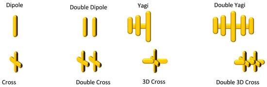
Figure 1.
Some resonating nanoantenna shapes for improved energy transfer in laser-matter interactions.
Figure 2 shows 3D-crossed antenna (yellow), laser pulse propagation (red arrow) and polarizations of the radiation field E (green vectors). Dipole-based antennas were aligned with the laser polarization vector.
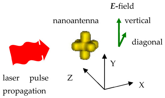
Figure 2.
Schematics of the 3D-crossed nanoantenna and laser radiation with vertical or diagonal polarizations.
Simulations tracked electron and ion energies, density distributions, and momentum, generating a dataset of ~1 TB. The data analysis was performed with external software: LLNL VisIt 3.1.3, Mathematica 9.0, and Python 3.12.3 libraries Matplotlib. 3.10 Visualization of the analyzed quantities was accomplished with Python-based custom tools and LLNL VisIt software with an ad hoc installed plug-in for the EPOCH databases. Video rendering was performed with the Cyberlink PD18 software.
3. Energy Enhancement by Nanoantennas
Proton energy gains in hydrogen-rich media are strongly influenced by the geometry of embedded nanoantennas. For single dipoles under moderate laser fields (4 × 10¹⁷ W/cm2), proton energies reach ~0.12 MeV, as shown in Figure 3a. The electron density around dipoles exhibits pronounced peaks at the antenna tips due to localized surface plasmon resonance (LSP), which concentrates the electromagnetic field and enhances local ionization. These field enhancements are highly anisotropic, leading to directional acceleration of protons primarily along the polarization vector. At higher laser intensities (~4 × 10¹⁸ W/cm2), dipole antennas show saturation in proton energy (~0.12 MeV). This occurs because the intense field rapidly ejects conduction electrons, disrupting plasmon resonance, and reducing energy transfer efficiency.
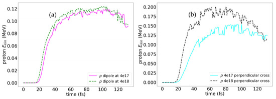
Figure 3.
Evolution of average energies of protons for a dipole (a) and crossed (b) nanoantenna in vertically polarized laser pulse of moderate intensity 4 × 10¹⁷ W/cm2—magenta solid line for dipoles (a), light blue solid line for crosses (b), and high intensity 4 × 10¹⁸ W/cm2—green dashed line for dipoles (a), black dashed line for crosses (b).
In contrast, crossed antennas provide higher proton energies (~0.15 MeV) (see Figure 3a) and a more uniform distribution of high-energy protons. The crossed configuration supports two orthogonal plasmonic modes, extending resonance lifetimes and increasing the effective interaction volume, achieving proton energies up to ~0.2 MeV in strong fields. Spatially resolved analysis reveals that protons experience multiple acceleration events within the field-enhanced regions around the crossed antennas, explaining their higher energies.
Advanced geometries provide more electrons and give multiple modes, while closely placed parallel antennas further increase the near field between them and thus increase proton energies. Double 3D-crosses and Yagi-type antennas give the strongest local electric field. Proton energies for these antenna configurations reach 0.4 MeV under 4 × 10¹⁸ W/cm2 radiation (see spatial distribution of the proton energies for a double 3D-cross at 62 fs of the laser pulse in Figure 4).
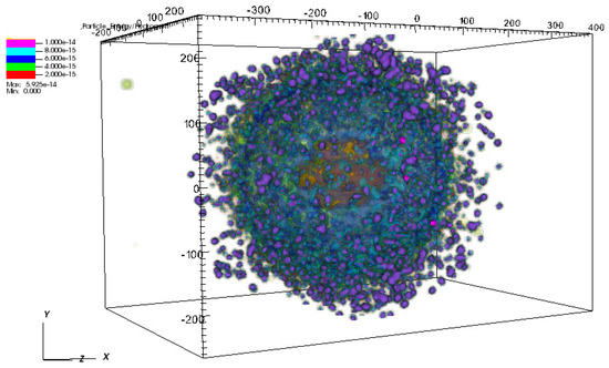
Figure 4.
Energies of ions in the strong field 4 × 10¹⁸ W/cm2 for the double 3D-cross nanoantenna at 62 fs of the laser pulse. The color scale legend denotes energies of the protons, increasing from red to lilac. Electrons, from H2—green and from gold—yellow, have almost entirely left simulation box at 62 fs; gold ions of the antenna are denoted by orange (behind proton cloud).
The comparison of the energies of protons for antenna shapes is visualized in Figure 5. Among various antenna shapes the close paired 3D cross yields the highest proton energies. The enhancement is not only in energy magnitude but also in proton population: simulations show 20–30% more protons achieving energies above 0.2 MeV compared to single dipoles. The energy distributions exhibit notable anisotropy: while dipoles concentrate protons along the laser polarization axis, crossed and 3D structures produce broader angular spreads, which may be advantageous for applications requiring uniform irradiation. Saturation effects are less pronounced for these geometries, as the coupled plasmonic modes allow sequential acceleration events and mitigate early electron depletion.
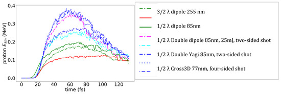
Figure 5.
Peak proton energies in strong field 4 × 10¹⁸ W/cm2 for various shapes of antennas (see legend).
Temporal analysis of proton energy evolution highlights the role of plasmon formation and lifetime. In dipoles, proton acceleration occurs primarily during the first 15–20 fs of the pulse, after which the ejected electrons reduce local fields. Crossed and 3D antennas sustain acceleration over ~30–40 fs, allowing protons to gain additional kinetic energy (see Figure 6).
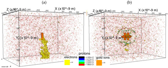
Figure 6.
Ion number density distribution for the antenna at the moment of detachment of the plasmon in strong field 4 × 10¹⁸ W/cm2 (a) dipole at 19 fs (b) double 3D-cross at 36 fs (b); electrons—yellow, gold ions—orange, protons—color scale (see legends).
These observations underscore the importance of nanoantenna design in tuning energy transfer efficiency. Importantly, a cross-based antenna resonates well with radiation coming from multiple sides. We tested numerically two-sided and four-sided laser shots vs. one-sided radiation and found that a multisided laser shot enhanced the proton energies especially in moderate laser fields.
4. Dependence on Laser Pulse Duration for Dipole Antennas
The increase in the intensity of the laser radiation over some high threshold does not necessarily yield the increase in the proton energies in a doped media. Indeed, the dynamics of the electromagnetic wave propagation seems the following: under intense irradiation (~1018 W/cm2), the polymer surface, initially dielectric, rapidly ionized, producing a dense plasma layer on the dielectric polymer; in this regime the incident electromagnetic wave no longer propagates deeply as in a normal dielectric. The plasma immediately modifies the local dielectric response: the real part of the permittivity becomes strongly negative, and the material transitions from a dielectric to a plasma-like conductor. As a result, the skin effect governs the laser’s penetration; the field penetrates only over a short relativistic skin depth, typically on the order of tens to hundreds of nanometers. Inside this thin layer, the oscillating electric field drives electrons to relativistic velocities, strongly modifying the local refractive index and producing nonlinear effects such as self-induced transparency at sufficiently high intensity. Gold nanoantennas embedded near the surface experience strong field enhancement during the initial dielectric phase, but once the surrounding polymer ionizes, the optical response becomes plasma-like and the plasmonic behavior is rapidly altered.
Overall, the laser field inside the interaction region is governed by plasma electrodynamics, not by standard optical propagation in matter: the wave sees a reflective, overly dense surface, penetrates only over the relativistic skin depth, and interacts with nanoantennas within that thin layer where extreme, rapidly varying fields are present.
Experiments were performed at Extreme Light Infrastructure ELI (Szeged, Hungary) laser facility [17] with infrared pulses of variable length ~12–500 fs with the energy 25 mJ and the wavelength λ = 795 nm irradiating UDMA–TEGDMA copolymer targets with embedded dipole dopes of 85 × 25 nm size. Using a fixed pulse energy of 25 mJ, our simulations cover durations from ~2.5 fs to 255 fs, corresponding to intensities from 4 × 10¹⁹ W/cm2 down to 4 × 10¹⁷ W/cm2 (see Table 1). Proton energies show a clear nonlinear dependence on pulse duration (Figure 7).

Table 1.
Pulse durations and approximate intensities for a fixed energy of 25 mJ.
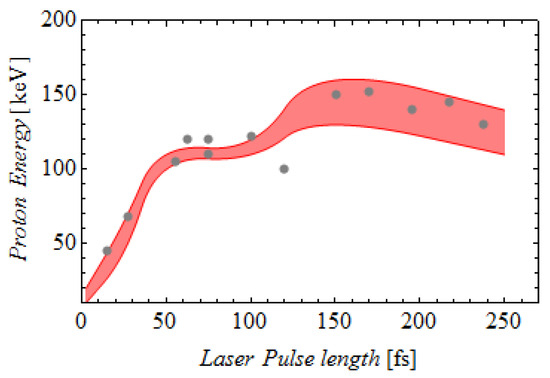
Figure 7.
Energy of protons for the duration of the pulse with 25 mJ energy in the presence of dipole dopes; gray points—experimental results from [17], colored curves—our theoretical results.
For very short pulse (~2.5 fs), peak intensities are extremely high, rapidly ejecting conduction electrons from the dipole and disrupting resonance. Consequently, proton energies remain modest (~0.05–0.07 MeV). As the pulse duration increases to ~102–145 fs, resonance is sustained longer, allowing more efficient energy transfer from the plasmonic field to the surrounding protons. Proton energies reach ~0.12 MeV, in agreement with experimental observations [17].
Our simulations also reveal inherent fluctuations in the maximum proton energy (~15%) across temporal snapshots due to stochastic variations in local ionization and electron dynamics. The average proton energy increases with pulse duration up to ~120 fs, after which it plateaus, reflecting a saturation phenomenon: longer pulses do not further enhance energy because the dipole reaches the maximal energy transfer limit.
To clarify the concept, we conclude that pulse duration is not the parameter playing a key role, but it is instead the laser field intensity that matters as far as the antennas not being destroyed. Very short pulses of very high intensity are not very effective as they prematurely destroy the antennas and the plasmonic resonance at the beginning of the pulse. This is consistent with experimental data, where proton energies for pulses shorter than 50 fs were systematically lower than for ~100 fs pulses [17].
5. Effect of Nanoantenna Geometry on Proton Energies
All comparisons of proton energy for different antenna shapes are consolidated in this section. Our simulations span dipoles, crossed antennas, double 3D crosses, and Yagi-like structures under moderate (~4 × 10¹⁷ W/cm2) and strong (~4 × 10¹⁸ W/cm2) fields.
- Dipoles: Saturation occurs at ~0.12 MeV already in a moderate field (Figure 3a). Increasing laser intensity does not increase proton energies significantly due to early conduction electron ejection and plasmon destruction. Proton distributions are highly directional along the polarization axis.
- Crossed antennas: Proton energies reach ~0.15 MeV in moderate fields and ~0.2 MeV in strong fields (Figure 3b). Crossed antennas naturally support orthogonal plasmonic modes due to their geometry; it helps to maintain resonance for longer and allows sequential proton acceleration.
- Three-dimensional crossed antennas further improve proton acceleration to 0.25 MeV. The angular spread of accelerated protons is broader compared to dipoles.
- Double 3D crosses: Optimized inter-antenna spacing (~40 nm) generates overlapping plasmonic hotspots. Proton energies increase to 0.35 MeV in a single-sided strong field and 0.4 MeV under two-sided irradiation (Figure 4 and Figure 5). Both energy magnitude and the number of high-energy protons are significantly increased compared to simpler geometries.
- Yagi-like antennas: Directional, asymmetric structures enhance field localization and proton energies beyond simple dipoles, though slightly below double 3D crosses (Figure 5). Symmetric double 3D crosses remain superior for isotropic acceleration and maximum energy.
Simulations confirm saturation effects for all antennas under intense fields (>4 × 10¹⁸ W/cm2). Dipoles saturate first (~0.12 MeV), followed by 2D crosses (~0.2 MeV). Three-dimensional structures prolong plasmonic activity, supporting higher proton energies and larger proton populations.
Mechanistic interpretation: Proton acceleration is driven primarily by plasmonic field enhancement, which reaches and exceeds an order of magnitude [10,11,12,13,14]. Close placement of antenna elements couples plasmons on the near surfaces and further boosts the field in between the double antennas. Saturation arises from rapid conduction electron loss, which terminates resonance. Crossed and 3D antennas sustain local fields longer, explaining higher energy ceilings and efficiency. Spatial maps (see for example, Figure 4) illustrate that high-energy protons cluster near plasmonic hotspots, confirming that antenna design directly controls acceleration efficiency.
Design recommendations: For high-energy proton production (>0.2 MeV), use crossed or 3D antennas with optimized spacing and short, intense pulses (~50 fs). For moderate energies (~0.12 MeV), dipoles with longer pulses (~100–150 fs) suffice. Antenna geometry also enables the tuning of angular spread for specific applications.
6. Results and Conclusions
Study spanning laser intensities 1017–1019 W/cm2 and pulse durations of 2.5–500 fs demonstrate:
- Dipole antennas: Proton energies saturate at ~0.12 MeV at moderate fields (4 × 10¹⁷ W/cm2). Saturation is caused by rapid ejection of conduction electrons, reducing plasmon resonance duration. Longer pulses modestly increase proton energies but cannot overcome saturation.
- Crossed antennas: Proton energies rise to 0.2 MeV, with extended plasmon lifetimes and polarization-insensitive acceleration. Electron density retention enables sequential acceleration, explaining higher energies and broader angular distributions.
- Advanced 3D geometries: Double 3D crosses and Yagi-like antennas reach proton energies of 0.4 MeV at 4 × 10¹⁸ W/cm2, producing both higher energy and increased proton populations. Optimized inter-antenna spacing (~40 nm) maximizes collective field enhancement.
- Pulse duration dependence: the intensity matters and thus short, intense pulses favor crossed, 3D- and double 3D-crossed antennas. Long pulses with lower intensity are preferable for dipoles. Proton energy gains are closely tied to plasmon intensity, lifetime and local field stability.
- Mechanistic interpretation: Plasmonic field enhancement is the dominant energy transfer mechanism. Saturation arises from conduction electron ejection and plasmon disruption. Crossed and 3D geometries have multimode resonance, which is sustained longer, enabling additional proton acceleration.
- Design guidelines: For high proton energies (>0.2 MeV), use crossed or 3D antennas with optimized spacing and short, intense pulses (~50 fs). For moderate energies (~0.12 MeV), single dipoles suffice with longer pulses. Angular spread can be tuned via antenna geometry for application-specific beam shaping as 3D antennas are not sensitive to beam direction, while Yagi antennas are strongly directional.
Some fusion reactions involving protons with energies > 0.2–1 MeV are listed in Table 2. It gives the idea of possible application of our results for nanofusion upon ionization of doped matter with protons energies achieved in the presence of dipole, crossed, 3D-crossed, and double crossed nanoantennas.
Table 2.
Some fusion reactions and their energy output for protons with energy >0.2 MeV.
This study quantitatively demonstrates the interplay of nanoantenna geometry, laser pulse parameters, and plasmon dynamics in laser-driven proton acceleration. The findings provide actionable design strategies for compact, high-energy proton sources in inertial fusion and high-energy-density applications, bridging simulation predictions with experimental observations [17]. Moreover, our study clearly illustrates that 2D or 3D shaped dopes allow proton energies > 0.2 MeV, which opens prospective for an array pf possible fusion reaction and paves the way to energy production in nanofusion reactor.
Author Contributions
Conceptualization, K.Z. and I.P.; methodology, K.Z. and I.P.; software, I.P.; validation, K.Z. and I.P.; formal analysis, K.Z.; investigation, K.Z. and I.P.; data curation, K.Z. and I.P.; writing—original draft preparation, K.Z.; writing—review and editing, K.Z.; visualization, K.Z. and I.P. All authors have read and agreed to the published version of the manuscript.
Funding
Both authors K.Z. and I.P. acknowledge support from the Hungarian Office for Research, Development and Innovation (NKFIH) under project number 2022-2.1.1-NL-2022-00002. K.Z. also acknowledges support from the project NKFI-Advanced 150038.
Data Availability Statement
Data is not publically available due to technical reasons (huge data volume), in part it might be obtained from the authors on request.
Conflicts of Interest
The authors declare no conflict of interest.
References
- Purvis, M.A.; Shlyaptsev, V.N.; Hollinger, R.; Bargsten, C.; Pukhov, A.; Prieto, A.; Wang, Y.; Luther, B.M.; Yin, L.; Wang, S.; et al. Relativistic plasma nanophotonics for ultrahigh energy density physics. Nat. Photonics 2013, 7, 796–800. [Google Scholar] [CrossRef]
- Chlouba, T.; Shiloh, R.; Kraus, S.; Brückner, L.; Litzel, J.; Hommelhoff, P. Coherent nanophotonic electron accelerator. Nature 2023, 622, 476–480. [Google Scholar] [CrossRef] [PubMed]
- Shiloh, R.; Chlouba, T.; Yousefi, P.; Hommelhoff, P. Particle acceleration using top-illuminated nanophotonic dielectric structures. Opt. Express 2021, 29, 14403–14411. [Google Scholar] [CrossRef] [PubMed]
- Tanabe, K. Plasmonics for Hydrogen Energy; Springer: Berlin/Heidelberg, Germany, 2022. [Google Scholar]
- Kern, C.; Zürch, M.; Petschulat, J.; Pertsch, T.; Kley, B.; Käsebier, T.; Hübner, U.; Spielmann, C. Comparison of femtosecond laser-induced damage on unstructured vs. nano-structured Au-targets. Appl. Phys. A 2011, 104, 15. [Google Scholar] [CrossRef]
- Halas, N. Playing with Plasmons: Tuning the Optical Resonant Properties of Metallic Nano shells. MRS Bull. 2005, 30, 362–367. [Google Scholar] [CrossRef]
- Bardhan, R.; Grady, N.K.; Ali, T.; Halas, N.J. Metallic Nanoshells with Semiconductor Cores: Optical Characteristics Modified by Core Medium Properties. ACS Nano 2010, 4, 6169–6179. [Google Scholar] [CrossRef] [PubMed]
- Chen, Y.; Wu, H.; Li, Z.; Wang, P.; Yang, L.; Fang, Y. The Study of Surface Plasmon in Au/Ag Core/Shell Compound Nanoparticles. Plasmonics 2012, 7, 509–513. [Google Scholar] [CrossRef]
- Papp, I.; Bravina, L.; Csete, M.; Mishustin, I.N.; Molnár, D.; Motornenko, A.; Satarov, L.M.; Stöcker, H.; Strottman, D.D.; Szenes, A.; et al. Laser wake field collider. Phys. Lett. A 2021, 396, 12724. [Google Scholar] [CrossRef]
- Zsukovszki, K.; Papp, I. Numerical Study of Ionization Dynamics in Matter with Gold Nanoparticles Upon Laser Irradiation of Various Intensities. Particles 2025, N8, 27. [Google Scholar]
- Zsukovszki, K.; Papp, I. Numerical analysis of ionization and plasmonic phenomena on gold nanodopes upon laser pulse irradiation. Results Phys. 2025, 72, 108198. [Google Scholar] [CrossRef]
- Zsukovszki, K.; Papp, I. Ionization of matter with resonating nanoantennas under intense laser irradiation—Numerical study. Rad. Phys. Chem. 2025, 237, 113111. [Google Scholar] [CrossRef]
- Papp, I.; Zsukovszki, K. Particle simulation of various gold nanoantennas in laser-irradiated matter for fusion production. Eur. Phys. J. Spec. Top. 2025, 234, 2993–2998. [Google Scholar] [CrossRef]
- Zsukovszki, K.; Papp, I. Comparative Analysis of Optical Absorption and Resonating Dynamics of Nanoantenna Dopes at Intense Laser Shots. Eur. Phys. J. Spec. Top. 2025, 234, 3021–3028. [Google Scholar] [CrossRef]
- Csernai, L.P.; Kroó, N.; Papp, I. Radiation-dominated implosion with nano-plasmonics. Laser Part. Beams 2018, 36, 171. [Google Scholar] [CrossRef]
- Papp, I.; Bravina, L.; Csete, M.; Kumari, A.; Mishustin, I.N.; Molnár, D.; Motornenko, A.; Rácz, P.; Satarov, L.M.; Stöcker, H.; et al. Kinetic Model Evaluation of the Resilience of Plasmonic Nanoantennas for Laser-Induced Fusion. PRX Energy 2022, 1, 023001. [Google Scholar] [CrossRef]
- Kroo, N.; Csernai, L.P.; Papp, I.; Kedves, M.A.; Aladi, M.; Bonyár, A.; Szalóki, M.; Osvay, K.; Varmazyar, P.; Biró, T.S.; et al. Indication of p+ 11B reaction in Laser Induced Nanofusion experiment. Sci. Rep. 2024, 14, 30087. [Google Scholar] [CrossRef] [PubMed]
- Arber, T.D.; Bennett, K.; Brady, C.S.; Lawrence-Douglas, A.; Ramsay, M.G.; Sircombe, N.J.; Gillies, P.; Evans, R.G.; Schmitz, H.; Bell, A.R.; et al. Contemporary particle-in-cell approach to laser-plasma modelling. Plasma Phys. Control Fusion 2015, 57, 113001. [Google Scholar] [CrossRef]
- Available online: https://epochpic.github.io/#about (accessed on 13 October 2025).
- Maier, S.A. Plasmonics: Fundamentals and Applications; Springer Science and Business Media: New York, NY, USA, 2007. [Google Scholar]
- Papp, I.; Bravina, L.; Csete, M.; Kumari, A.; Mishustin, I.N.; Motornenko, A.; Rácz, P.; Satarov, L.M.; Stöcker, H.; Strottman, D.D.; et al. Kinetic model of resonant nanoantennas in polymer for laser induced fusion. Front. Phys. 2023, 11, 1116023. [Google Scholar] [CrossRef]
- Novotny, L.; Hecht, B. Principles of Nano-Optics; Cambridge University Press: Cambridge, UK, 2012; ISBN 1107005469, 9781107005464. [Google Scholar]


Disclaimer/Publisher’s Note: The statements, opinions and data contained in all publications are solely those of the individual author(s) and contributor(s) and not of MDPI and/or the editor(s). MDPI and/or the editor(s) disclaim responsibility for any injury to people or property resulting from any ideas, methods, instructions or products referred to in the content. |
© 2025 by the authors. Licensee MDPI, Basel, Switzerland. This article is an open access article distributed under the terms and conditions of the Creative Commons Attribution (CC BY) license (https://creativecommons.org/licenses/by/4.0/).