1. Introduction
Short carbon-fiber-reinforced plastics (SFRPs) offer distinct advantages over continuous carbon-fiber-reinforced plastics (CFRPs) in terms of cost-effective manufacturing for intricate geometries and end-of-life recyclability. However, their mechanical properties are generally inferior to continuous CFRPs with similar constituent materials. Recent advancements in high-performance SFRPs, such as randomly oriented strands (ROSs) and tow-based discontinuous composites (TBDCs), have demonstrated the potential to bridge the gap between processability and mechanical performance. These innovations enhance the circularity of composite materials by enabling reusability while maintaining structural integrity.
However, the performance of high-performance SFRP is inherently dependent on their microstructural features. Fiber orientation distributions, void content, and resin impregnation quality critically influence mechanical behavior. Moreover, the high flowability during compression molding can exacerbate non-uniform microstructures, leading to unpredictable property variations. This sensitivity necessitates a comprehensive understanding of how processing parameters affect internal structures to enable reliable design and optimization.
Previous studies on high-performance SFRP have primarily focused on mechanical characterization and constitutive modeling. Feraboli et al. evaluated the mechanical properties of ROSs and proposed a stochastic laminate analogy model for modulus prediction [
1,
2,
3,
4]. Li and Pimenta et al. [
5,
6,
7] developed a shear-lag model for TBDCs, which can also be sorted to the “laminate analogy” model, demonstrating improved accuracy in simulating nonlinear responses and failure mechanisms. Selezneva et al. investigated the fabrication and mechanical behavior of their carbon-fiber sheet molding compounds (CF-SMCs) [
8,
9], they also introducing a simplified 2D model for strength and modulus prediction [
10]. Researchers at the University of Tokyo have systematically studied carbon-fiber-reinforced thermoplastic sheet molding compounds (CFRTP-SMCs) and conducted research on the fabrication, evaluation, and simulation of CFRTP-SMCs [
11,
12,
13,
14,
15,
16]. Collectively, their works underscore the profound influence of processing on microstructures and mechanical performance [
11]. And the scatter of mechanical properties is simulated by using a Monte Carlo-based model [
14]. The molding process and prepreg thickness effects on the mechanical properties were also studied experimentally [
16]. In recent years, increasing research efforts have focused on CF-SMCs and the relationship between molding parameters and the resulting mechanical properties [
17,
18,
19,
20]. Wang et al. [
17] provided a comprehensive review of recent molding techniques and their associated applications. Cui et al. [
18] reported enhanced impregnation quality in CFRTP-SMCs by employing a PEEK matrix. Zhao et al. [
19] investigated the influence of deliberately induced unidirectional flow during molding on the mechanical performance of CFRTP-SMCs. Furthermore, Wan et al. [
20] analyzed the effect of prepreg thickness on the internal geometry and mechanical properties of compression-molded CFRTP-SMCs.
Notwithstanding these advancements, a critical knowledge gap persists: the lack of systematic quantification of how specific molding processes alter internal structures across different SFRP systems. Existing studies have not established a direct correlation between processing parameters and internal structures under varying conditions. This deficiency hinders the development of predictive models and robust manufacturing protocols for high-performance SFRP.
Against this backdrop, this study systematically evaluates the effects of compression molding processes on the internal structures of three SFRP systems: CFRTP-SMC, CFRTP bulk molding compounds (BMCs), and CFRTP free-edge molding compounds (FMC). These materials were selected with the consideration of different molding processes and potential applications. The difference in fiber flow during compression molding lead to varying degrees of microstructural complexity. Using X-ray computed tomography (XCT) and advanced image analysis, this study evaluates fiber orientation distributions, void, and impregnation quality of the SFRP and thereby provide industrial application guideline and advancing the industrial implementation of high-performance SFRP.
2. Materials and Methods
2.1. Material Fabrication
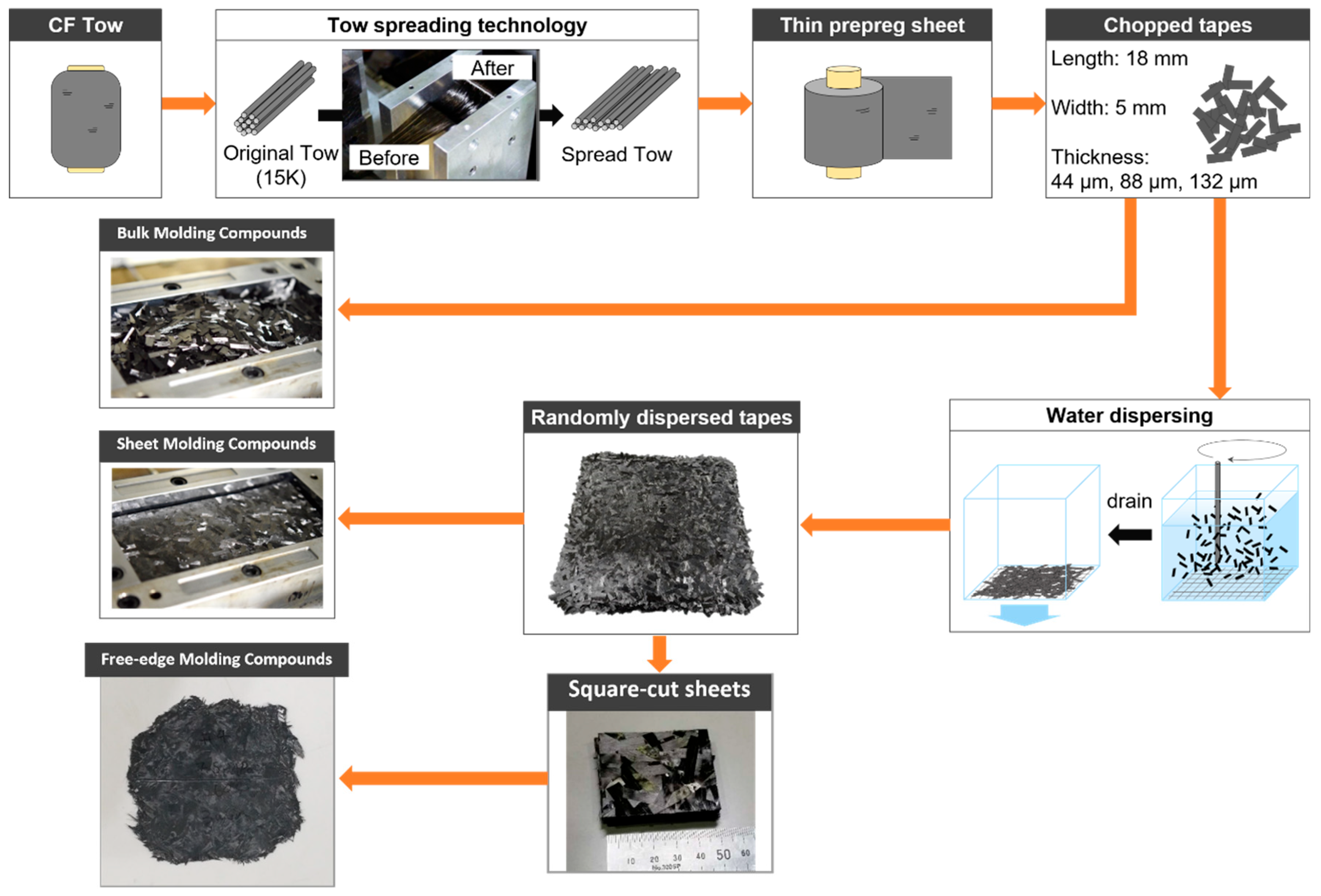
A CFRTP-SMC, BMC, and FMC were fabricated in this study. The main difference between these three SFRP is the tape dispersion processes.
Figure 1 exhibits the fabrication flow chart of the CFRTP-SMC, BMC, and FMC. Carbon fiber tows (TR50S, Mitsubishi Chemical Co., Tokyo, Japan) were first spread using an air-jet spreading technique to create unidirectional prepreg tapes. These tapes were then laminated with polyamide-6 (PA6, DIAMIRON™ C, Mitsubishi Chemical Co.) films via compression molding to form thin prepreg sheets with an average thickness of 50 μm. The prepreg sheets were subsequently chopped into rectangular segments measuring 18 mm in length and 5 mm in width.
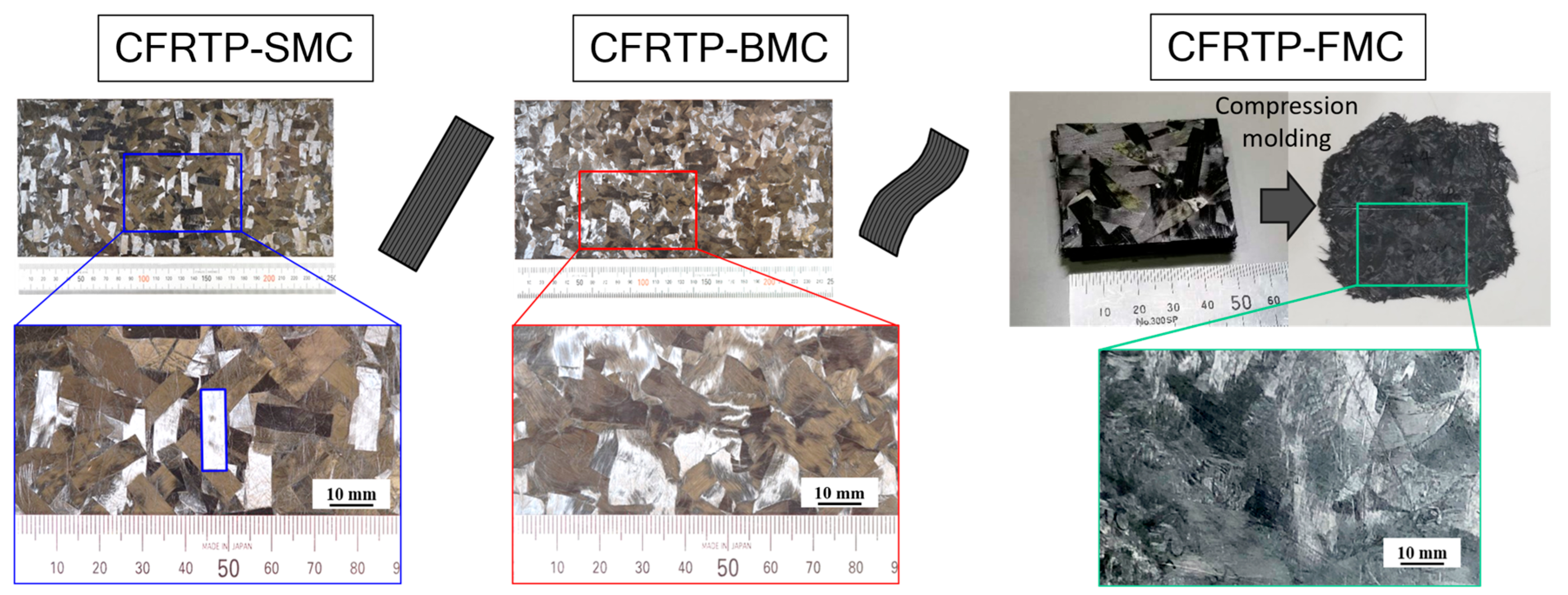
For the CFRTP-BMC, the tapes were weighted to approximately 100 g and randomly placed directly into a pressing die with a 250 mm × 125 mm geometry for compression molding. Otherwise, CFRTP-SMC production involved a wet-layup process—the chopped tapes were first suspended in water to achieve random dispersion, then filtered to form intermediate sheets. The intermediate sheets were dried and consolidated in a hot press at 1.0 MPa, which vaporized residual water and preserved their shape. A total of 8 layers of these intermediate sheets (approximately 100 g total weight) were stacked in the same molding die for compression molding. Moreover, the CFRTP-FMC needs the control of follow area, hence 8 layers of 5 mm square-cut CFRTP-SMC intermediate sheets, which is approximately 12 g, were stacked and placed into the center of the molding die for compression molding. The plates of the CFRTP-SMC and CFRTP-BMC after molding were about 2mm in thickness. The compression molding conditions of all the SFRPs are identical in this study. The pressing die was heated to 250 °C and the compression pressure was 5 MPa for 10 min. The surface appearance of the CFRTP-SMC, BMC, and FMC are illustrated in
Figure 2. After molding the CFRTP-SMC, BMC, and FMC materials, the actual fiber volume fraction and void volume fraction were determined using the ash test on five specimens, based on the ignition loss of the polymer matrix in an inert gas atmosphere [
11].
2.2. XCT Characterization
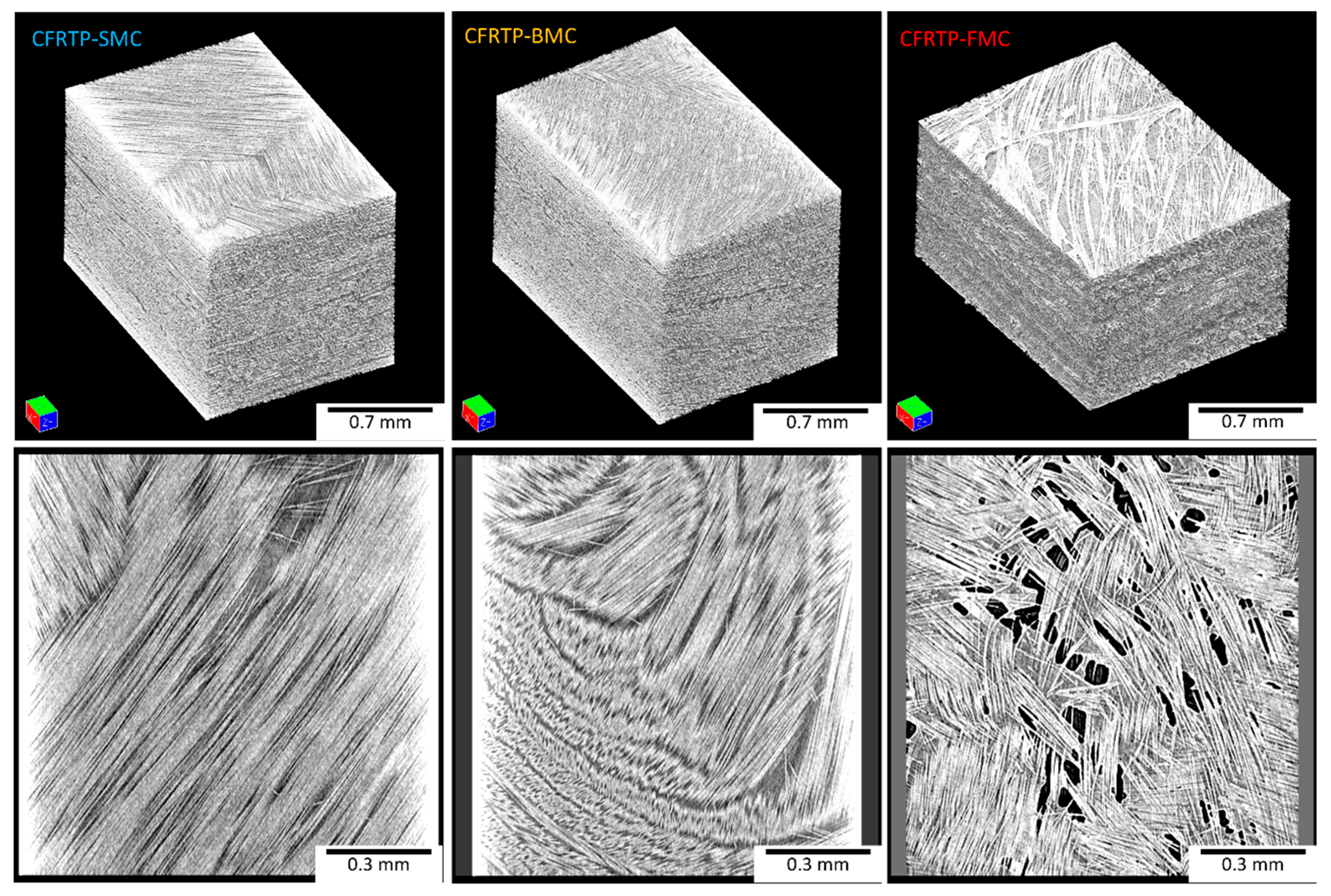
Compared with other microstructural observation techniques, XCT can resolve the full three-dimensional fiber architecture, and subsequent image-processing routines enable highly accurate visualization and quantification of the internal geometry. To accurately analyze the internal structures of the fabricated CFRTP samples, specimens with dimensions of 2 × 2 × 30 mm were carefully extracted from the molded plates of each SFRP system. For all CFRTP-SMC, BMC, and FMC XCT specimens, the central region was selected to ensure the repeatability of the study. These specimens were then scanned using a TDM1000-II μ-CT scan system (Yamato Scientific Co., Ltd., Tokyo, Japan) operating at 40 kV and 40 μA with a high resolution of 3.4 μm voxels.
Subsequently, VoxTex software (v1.16, CMG, KU Leuven, Belgium), a proprietary image analysis tool, was utilized to perform detailed quantifications. The software was employed to determine the in-plane and out-of-plane orientation, the angle relative to the molding plane, via 3D tensor analysis. By analyzing the orientation of each voxel within the scanned volume, the software calculated the average in-plane and out-of-plane orientation of the composites.
In addition, the orientation information calculated from VoxTex was input into ParaView from Kitware and generated the 3D model with visualized orientation distribution information.
3. Results and Discussions
3.1. Results
The ash test results of the CFRTP-SMC, BMC, and FMC with the actual fiber volume fraction and void volume fraction were listed in
Table 1.
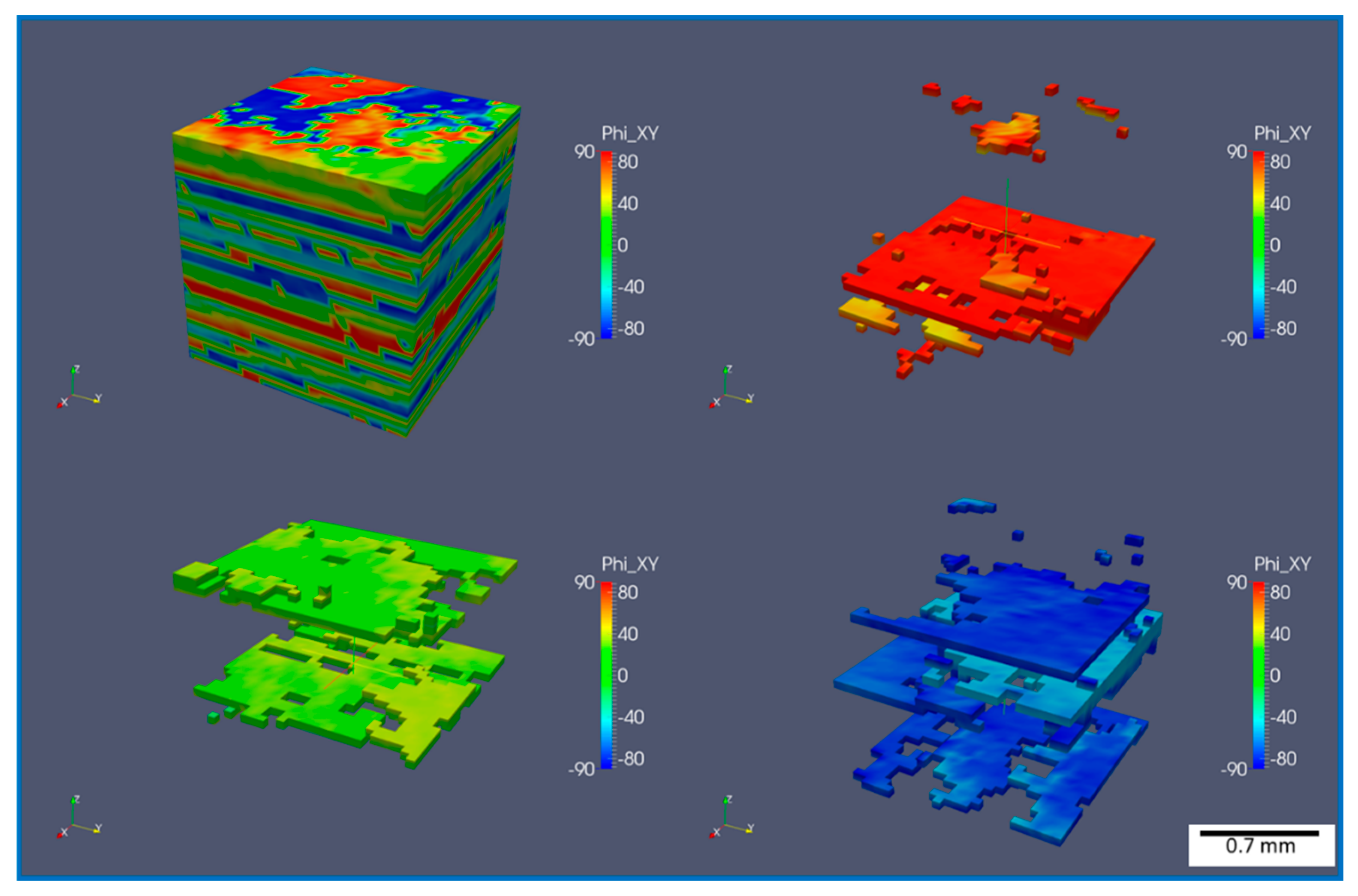
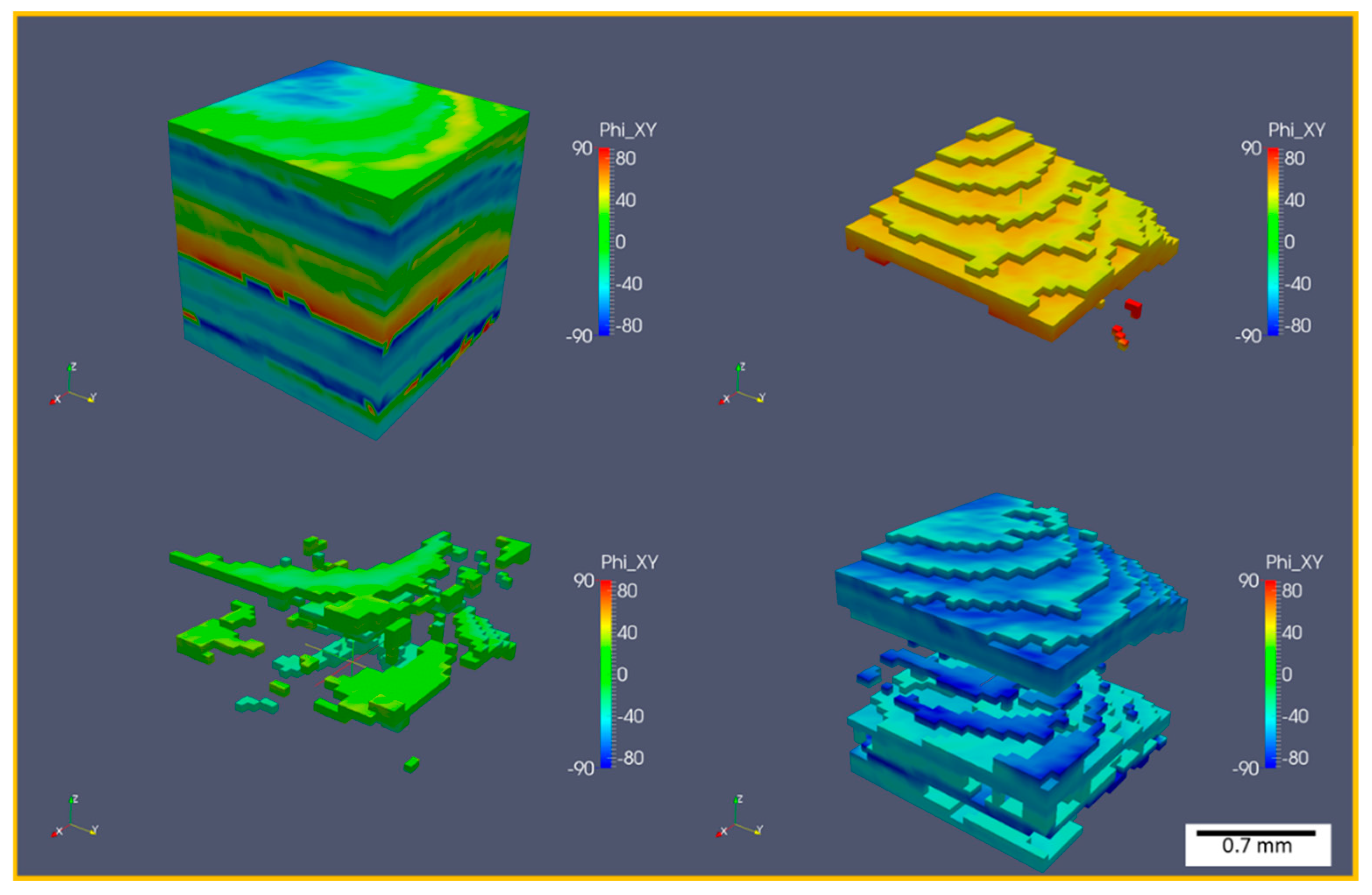
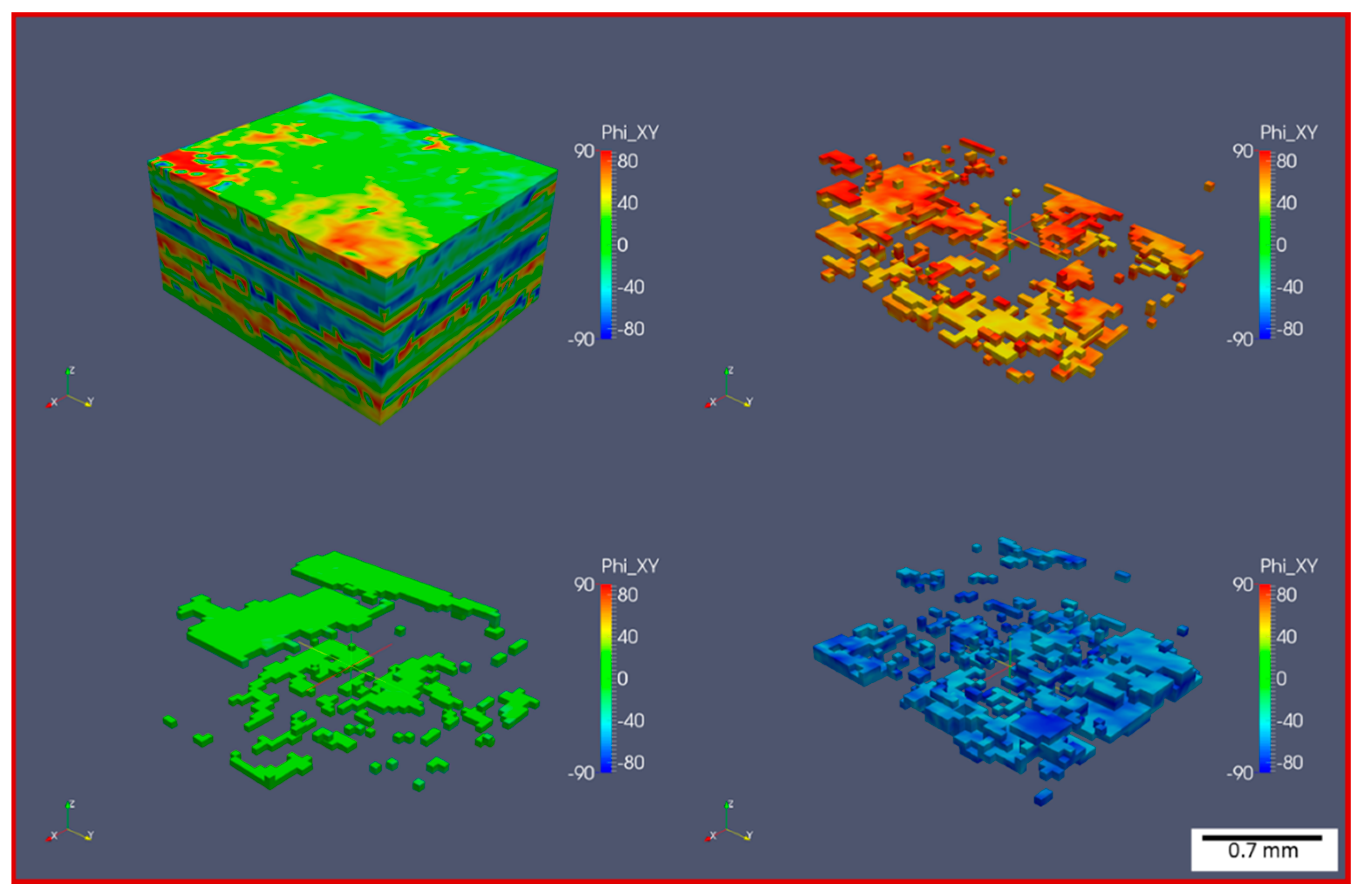
Figure 3 shows the XCT 3D models and in-plane images of the three material systems. In the CFRTP-SMC, the fibrous tapes remain largely intact and exhibit good impregnation by the polymer matrix. The fibers within each tape also show a high degree of alignment. In contrast, CFRTP-BMC displays more tape deformation and splitting, with notable fiber curvature in both the in-plane and out-of-plane directions. Despite these structural changes, the overall impregnation quality in the CFRTP-BMC remains similar to that of the CFRTP-SMC. Meanwhile, the CFRTP-FMC reveals the most pronounced tape distortion and a considerable amount of unimpregnated regions, indicating that molding flow significantly compromised impregnation consistency.
Figure 4,
Figure 5,
Figure 6 and
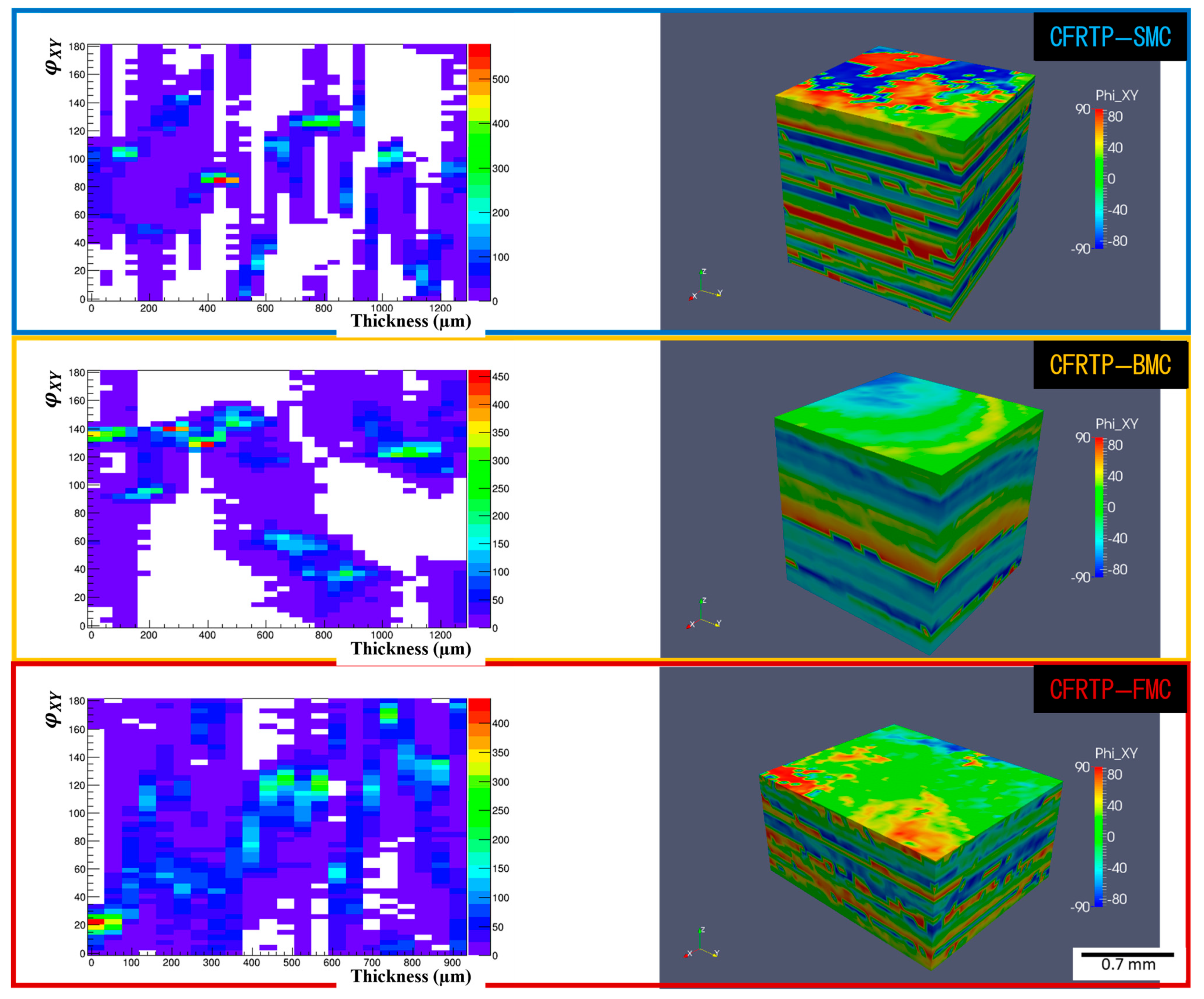
Figure 7 present the in-plane fiber orientation distribution (
) for each material and the generated 3D model with visualized
distribution. The CFRTP-SMC (
Figure 4 and
Figure 5) maintains its initial tape structure most effectively, with relatively uniform orientations and distinct lamination layers. This layered arrangement is easily visible in the 3D model and suggests minimal tape displacement during compression molding. By contrast, the CFRTP-BMC (
Figure 4 and
Figure 6) reveals tapes that are frequently deformed or clustered, with orientation “clusters” forming throughout the thickness. These clusters point to increased tape-to-tape contact in certain zones, most likely caused by higher flow stress during pressing. The CFRTP-FMC (
Figure 4 and
Figure 7) exhibits even more scattered fiber distributions. The tape morphology is barely recognizable, and the overall in-plane orientation shows more randomness, likely due to stronger in-plane flow within the free-edge molding region.
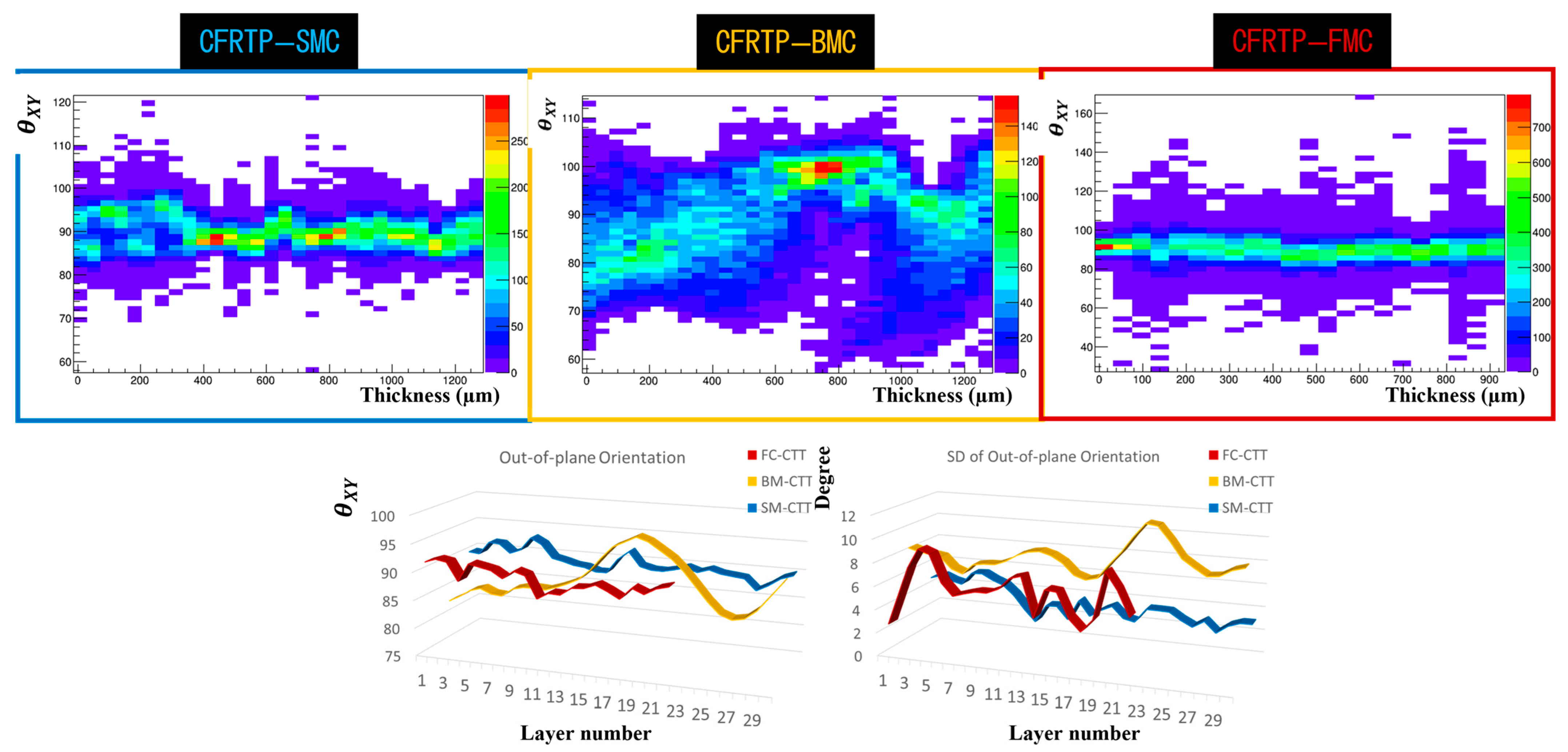
Figure 8 illustrates the out-of-plane orientation distribution (
) for each system. In the CFRTP-SMC, the majority of fibers remain oriented in-plane, reflecting the retention of tape structure observed in
Figure 4 and
Figure 5. The CFRTP-BMC shows a broader range of out-of-plane orientations, consistent with the deformation and splitting noted in
Figure 6. Interestingly, the CFRTP-FMC exhibits a more stable in-plane orientation when viewed from an out-of-plane angle perspective, but this seemingly “stable” average is largely due to the extensive tape fragmentation. Because the original tape layout is lost, the recorded orientation distribution is influenced by smaller, dispersed fiber segments rather than consolidated tape structures.
Overall, the XCT results suggest that CFRTP-SMC experiences the least structural disruption during molding, retaining a clear laminate-like morphology with good impregnation. The CFRTP-BMC undergoes more deformation, especially in the through-thickness direction, while still preserving acceptable impregnation. The CFRTP-FMC demonstrates the most compromised impregnation and tape integrity, with significant randomization of fiber orientation driven by freer flow conditions at the edges. These variations in internal architecture provide essential insights for understanding how different molding processes can alter fiber orientation and impregnation quality in high-performance discontinuous CFRTP.
3.2. Discussions
The internal structures and the void volume fractions of the CFRTP-SMC, BMC, and FMC exhibit clear differences following compression molding. The CFRTP-SMC retains its original tape geometry most effectively, which leads to well-defined layer boundaries and good impregnation. This is supported by its stable distribution and limited variation. These features suggest that tape deformation is minimal, allowing the fibers to remain aligned and the resin to infiltrate the network uniformly.
The CFRTP-BMC, in contrast, shows more pronounced tape deformation and splitting. Although the overall impregnation quality remains comparable to that of the CFRTP-SMC, the formation of tape clusters, the observed tape “sticking”, and the broader range of out-of-plane orientations imply that local flow disturbances can significantly alter tape morphology during molding. Higher pressures and resulting flow forces appear to displace tapes through the thickness, thus reducing alignment consistency and potentially creating internal stress concentrations.
CFRTP-FMC displays the least orderly internal structure. Not only do tapes lose their recognizable shape, but unimpregnated regions also become more frequent, as does the much higher void. These issues are likely due to a more complex molding flow path and reduced in-plane pressure at the free edge, which hinder resin infiltration and disrupt fiber alignment. Interestingly, the out-of-plane orientation distribution of the CFRTP-FMC shows relatively fewer variations, but this consistency seems to arise from extensive tape splitting and scattered fiber bundles rather than a stable tape-based arrangement.
Taken together, these observations indicate that the CFRTP-SMC is best able to preserve targeted fiber alignment and impregnation, which may lead to more predictable mechanical properties. Meanwhile, increased flow-induced deformation in the CFRTP-BMC introduces structural complexity that could affect performance, despite generally satisfactory impregnation. But, its molding process is simpler than that of the CFRTP-SMC, and the observed tape deformations indicate a possible shape tolerance that could be beneficial for recycled applications. The severe fragmentation and inconsistent impregnation in the CFRTP-FMC emphasize the importance of controlling flow conditions and maintaining appropriate pressure fields, especially in regions prone to free-edge effects.
4. Conclusions
This study used an XCT analysis method based on VoxTex to examine how molding processes affect the internal structures of three discontinuous CFRTP systems (SMC, BMC, FMC) to compression molding processes. To the best of our knowledge, this is the first study on this topic within this category of materials.
The CFRTP-SMC retained clear tape layers with minimal distortion, suggesting stable mechanical properties and good compatibility with CAE tools. The CFRTP-BMC displayed more tape deformation and splitting under higher flow, but its simpler molding process and shape tolerance could benefit recycled applications. The CFRTP-FMC showed the poorest impregnation and most fragmented tapes, with free-edge flow creating large unimpregnated areas.
These results highlight the importance of managing flow and pressure to preserve tape morphology. The XCT technique quantifies critical structural parameters for industrial and research use, supporting improved mechanical performance and design predictability in high-performance discontinuous CFRTP. A follow-up study that integrates molding parameters, internal structural characterization, and mechanical property evaluation is currently underway to yield further insights.


