Abstract
Conductive polymers (CPs), such as polypyrrole (PPy), have shown promising properties for use as electro-responsive bioactive scaffolds for tissue regeneration. PPy can be synthesized by chemical electrosynthesis and doped with biomolecules such as hyaluronic acid (HA). Taking advantage of the electrochemical synthesis versatility, nanofibers for surface-modified indium tin oxide (ITO) electrodes can be used as templates to produce tridimensional HA-doped PPy scaffolds. In this study, polyvinyl alcohol/chitosan (PVA/CTS) electrospun nanofibers deposited on ITO electrodes were used as a 3D template for the in situ electrosynthesis of HA-doped PPy to produce a bioactive scaffold for tissue engineering. The final material gathers the advantages of each biopolymer, the porous morphology of the nanofiber, and the conductivity of the electrosynthetized polymer. Furthermore, the biological activity of the NF-PVA/CTS@PPy:HA composite was evaluated in NIH-3T3 fibroblasts by MTT, resulting in a cell viability of 146 ± 40% and wound-healing capacity of 97 ± 1.9% at 24 h of culture.
1. Introduction
Electrical signals, including neural communication, embryonic development, heartbeat and tissue repair, regulate many functions of the human body [1]. Thus, materials that interface with electrically active tissues for a biomedical purpose are desirable in order to be able to incorporate conductive components that enhance the biological response to external stimuli and cellular specialization [1,2]. This could help enhance the healing procedure through improving signaling between cells and allowing the local delivery of external electrical stimuli [3]. Hence, conductive scaffolds improve tissue repair overall and decrease healing time after traumatic injuries [4].
Conductive polymers (CPs) have been widely utilized in biomedical engineering as scaffolding materials because they combine the flexibility and ease of processing found in polymers with the electroconductivity of metals and semiconductors [4]. In addition, they can provide electrical stimulus for tissue genesis and the growth of various cells, including bone and nerve cells [5]. Therefore, these kinds of polymers are promising for many applications due to their tunable physicochemical properties, mechanical flexibility, low weight, good biocompatibility, and scalable production [6].
Polypyrrole (PPy) is one of the main CPs used in biomedicine for scaffolding applications due to its non-toxicity and biocompatibility [7,8]. This CP exhibits unique features, including easy synthesis, environmental stability, and high electrical conductivity [5,8]. In addition, PPy-based biomaterials can improve their biomimetic feature by incorporating biomacromolecules, such as hyaluronic acid salt (HA) [5,9], which is a major component of connective tissues in the body. Moreover, it can provide characteristic biological interactions with living cells/tissues to the conductive material [9].
Several processing techniques allow CPs to be shaped into gels, films, and nanofibers, enabling their use as electroactive fabrics, sensors, and tissue scaffolds [6,10]. Nonetheless, nanofibers offer many advantages over other materials, such as uniformity, porosity, large surface area, enhanced mechanical strength, and extracellular matrix mimicking to be used as scaffolding material [6]. In this sense, despite its advantages, the use of PPy in tissue engineering is limited by several drawbacks; i.e., it is unsuitable for soft tissues due to its brittleness [11], and its poor solubility, low molecular weight, and rigid backbone make it challenging to process using scaffold fabrication methods such as electrospinning [10].
To produce nanofiber structures based on CPs, neat, coaxial, and co-electrospinning have also been employed. However, several disadvantages have been observed after electrospinning, including poor mechanical properties, and particularly in coaxial configurations, lower conductivity than neat CPs, poor adhesion, and the need for additional processing steps [10]. Therefore, although several important efforts have been made to improve the spinnability of CPs, electrospinning remains a challenge.
Electrochemical polymerization is preferred for incorporating CPs on electrospun nanofiber 3D structures due to it being a versatile, controllable, easy-to-prepare, fast, and convenient methodology [12].
Chitosan (CTS) and polyvinyl alcohol (PVA) are non-conductive polymers that can serve as ideal nanofiber templates for incorporating CPs by electropolymerization. CTS is at the top of research preferences in designing nanofibrous materials [13] due to its biodegradability and non-toxicity as well as its bacteriostatic, antioxidant, antitumor, anti-inflammatory and antifungal properties [14]. Nonetheless, it is poorly electrospinnable because of the high viscosity and surface tension of its solutions [15,16]. Therefore, it is commonly mixed with a highly electrospun polymer, such as PVA, due to it being an ideal co-electrospinning component to improve CTS’s spinnability [17]. PVA is a biodegradable, highly biocompatible, and non-toxic semicrystalline synthetic polymer that has been used successfully in the biomedical field for several years [18]. Hybrid materials can be produced that take advantage of the strengths of each component [15].
To explore new applications of PVA/CTS-based nanofibers, different investigations have addressed the enhancement of electrical conductivity of PVA/CTS-based nanofibers with the aim of applying them in specialized tissue regeneration, such as cardiac and nerve tissues [19,20,21,22]. However, there are only a few reports on the incorporation of CPs into PVA/CTS-based nanofibers via the electrospinning of solution blends containing CPs, specifically poly(3,4-ethylenedioxythiophene) (PEDOT), polyaniline and aniline oligomer [23,24,25]. Some other combinations based on CTS containing CPs have also been explored, for example, PPy/CS/collagen electrospun nanofibers for tissue engineering, with better cell adhesion, growth, and proliferation than other compositions [26]. Additionally, CTS-grafted polythiophene and chitosan-grafted polythiophene/(poly (ε-caprolactone) electrospun nanofibers have demonstrated biocompatibility, biodegradability, and suitable electroactivity and conductivity [3].
To our knowledge, these are the only reports about the production of PVA/CTS-based nanofibers loaded with CPs.
PVA/CTS nanofibers are an attractive alternative for scaffold production because they have the appropriate physicochemical and biological properties that are suitable for template polymerization, yet they have not been used for this purpose until now. Therefore, this paper presents the use of PVA/CTS nanofibers in surface-modified ITO electrodes as a 3D template for the in situ electrosynthesis of HA doped PPy to produce a bioactive scaffold for tissue engineering. This work is the first step in incorporating electroactive components into PVA/CTS nanofiber-based cell scaffolds and evaluating their cytotoxicity, which will serve as a basis for subsequent evaluation as electro-responsive scaffolds to accelerate wound regeneration through electrostimulation.
2. Materials and Methods
2.1. Materials
CTS (medium molecular weight), PVA (MW 89,000–98,000 g/mol, hydrolysis degree >99%), pyrrole, hyaluronic acid sodium salt from Streptococcus equi (MW 8000–15,000 g/mol) and tetrabutylammonium perchlorate (TBAP purity ≥98%) were purchased from Sigma-Aldrich. Acetonitrile, acetic acid, ethyl alcohol, and methanol were purchased from J. T. Baker (Phillipsburg, NJ, USA). Sodium chloride solution 0.9 wt % was acquired from PiSA Pharmaceutical (Mexico City, Mexico).
2.2. Polymeric Solutions for Electrospinning
The proper quantity of PVA to prepare 8 wt % aqueous solutions was dissolved in distilled water and placed at 90 °C overnight until complete dissolution. Solutions of 4 wt % CTS were prepared using AA/H2O solutions at 70:30, 80:20, and 90:10 v/v ratios and left under magnetic stirring for 3 h at 60 °C.
Blends of PVA and CTS (1.5:1 v/v) were prepared by mixing the proper quantity of PVA 8 wt % with the 4 wt % CTS dissolutions and left under magnetic stirring at 70 °C for 1 h, which was followed by overnight magnetic stirring at room temperature.
2.3. Electrospinning Process Standardization
The electrospinning of different samples was performed in a TL-01 NaBond Technologies Co. electrospinning unit to establish suitable electrospinning parameters for obtaining high-quality PVA/CTS nanofibers. The analyzed parameters were voltage (10, 12 and 14 kV), flow rate (0.1, 0.3 and 0.5 mL/h), distance between electrodes (15, 17.5 and 20 cm), and polymer blend proportions (PVA/CTS 1:1 and 1.5:1 v/v). Standardization tests were carried out at room temperature, ambient relative humidity, and a processing time of 30 min for all the assays.
2.4. Fabrication of PVA/CTS Nanofibers
PVA/CTS nanofibers were obtained using the parameters established through the standardization process for the electrospinning of the polymeric blend PVA/CTS 1.5:1 v/v (using the AA/H2O (80:20 v/v) solvent ratio for CTS dissolution) described above.
2.5. PVA/CTS Nanofiber Mats Crosslinking
The thermal crosslinking was carried out by heating nanofiber mats on a heating grill at 140 °C for 40 min. This step is essential to preserve the microstructure of PVA/CTS nanofibers in aqueous medium.
2.6. Electrospinning of PVA/CTS Blend onto ITO Glass
PVA/CTS nanofiber mats were deposited onto ITO electrodes by electrospinning using the ITO electrodes as the electrospinning collector. The electrospinning parameters used were a voltage of 12 kV, a distance between electrodes of 17.5 cm, a flow rate of 0.5 mL/h, and a processing time of 12 h. The ambient temperature was 20–30 °C, and the relative humidity was 20–40%, which remained within these ranges by increasing and controlling the temperature inside the electrospinning chamber through a temperature controller on the equipment, which was monitored by a thermo-hygrometer. The obtained mats were employed as a template for the electrochemical polymerization/deposition of PPy:HA.
2.7. Electropolymerization/Deposition of PPy:HA onto PVA/CTS Nanofibers
PPy was obtained by pyrrole electropolymerization using a potentiostat/galvanostat Autolab PGSTAT204 from Metrohm (Shirley, NY, USA) in a standard three-electrode cell with a Pt auxiliary electrode (AE), an Ag0|AgNO3 reference electrode (RE) to monitor the polymerization process, and an ITO glass working electrode (WE). To improve the solubility of HA, a pyrrole monomer and HA with TBAP (supporting electrolyte) were dissolved in an aqueous solution of ACN as the working dissolution, adapting the experimental conditions previously reported to perform the electrodeposition of CP-based coatings on PVA nanofibers [27].
The working dissolution was prepared with 8 mM of pyrrole monomer, 17 mg/mL of TBAP, and 0.16 mg/mL of HA in a mixture of ACN/H2O 75:25 v/v. Before the electropolymerization process, the mixture was sonicated for 1 h at room temperature until the complete solubilization of HA.
PPy:HA potentiodynamic electropolymerization was carried out through cyclic voltammetry from −0.5 to 1.3 V vs. Ag0|AgNO3 with a starting and final potential of 0 V vs. Ag0|AgNO3 at a 0.05 V/s scan rate during 15, 20, and 50 cycles.
2.8. Characterization
2.8.1. Morphological and Chemical Structural Analysis
The microstructure of the nanofiber mats was analyzed using field emission scanning electron microscopy (FESEM, JOEL JSM-7600F; Midland, ON, Canada) equipped with a tungsten incandescent filament. The micrographs obtained were analyzed to determine the diameter distribution histograms with the OriginPro 9.0 software, considering 60 distinct nanofibers in each sample. Furthermore, the chemical structure of the polymers in the obtained materials was analyzed using Fourier-transform infrared spectroscopy (FTIR) on a Nicolet iS10 spectrometer (Thermo Scientific, Waltham, MA, USA).
2.8.2. Thermal Analysis
The thermal behavior of the obtained materials was analyzed by differential scanning calorimetry (DSC) and thermogravimetric analysis (TGA). The thermograms were obtained in a thermogravimetric analyzer model TGA/DSC 2 simultaneous Mettler Toledo under a dynamic atmosphere of N2 (50 mL/min) with a heating ramp-up of 5 °C/min from 25 to 500 °C. A first scan was performed from room temperature to 120 °C to eliminate moisture.
2.8.3. Solubility Test
A volume of 2 mL of EtOH, MeOH, H2O, ACN or physiological sodium chloride solution was added to PVA/CTS nanofiber aliquots (6 mm diameter) to investigate solubility. After 48 h of direct immersion in each solvent, the solvent was removed to determine the solubility of the nanofiber mats qualitatively.
2.8.4. Electrochemical Characterization
The electrochemical characterization of the obtained material via electropolymerization was carried out with a potentiostat/galvanostat Autolab PGSTAT302NM from Metrohm according to Pérez-Nava et al. [27]. Data were obtained in Nova 2.1 and re-plotted in Origin Pro 2024.
2.9. Cell Culture
2.9.1. 3T3-L1 Culture for Resazurin Reduction Assay
3T3-L1 fibroblasts from mouse embryo were seeded in high-glucose Dulbecco’s modified Eagle’s medium (DMEM, Sigma-Aldrich, St. Louis, MO, USA) supplemented with 10% heat-inactivated calf serum (Biowest, Bradenton, FL, USA) and penicillin/streptomycin (100/100 units/mL, Invitrogen) in a 5% CO2 humidified chamber set at 37 °C. Cells were trypsinized with trypsin–EDTA (0.25%, Sigma Aldrich, St. Louis, MO, USA). An indirect in vitro assay using 3T3-L1 cells was set up to evaluate the biocompatibility of the post-electrospinning functionalized NF-PVA/CTS@PPy:HA composites. The composites were cut into 30 mm diameter circles before UV light sterilization (15 min on each side), and 500 μL of complete DMEM was then added. The composites were incubated in a 5% CO2 humidified chamber at 37 °C for 24 h.
2.9.2. NIH-3T3 Cell Culture for MTT and Wound Closure Assays
NIH-3T3 mouse embryonic fibroblasts were seeded in high-glucose Dulbecco’s modified Eagle’s medium (DMEM, Capricorn Scientific, Ebsdorfergrund, Germany) supplemented with 10% heat-inactivated fetal bovine serum (Invitrogen) and penicillin/streptomycin (100/100 units/mL, Invitrogen, Waltham, MA, USA) in a 5% CO2 humidified chamber set at 37 °C. Cells were trypsinized with trypsin–EDTA (0.25%, Capricorn Scientific). An indirect in vitro assay using NIH-3T3 cells was set up to evaluate the cytotoxicity/viability of the post-electrospinning functionalized NF- PVA/CTS@PPy:HA composites. The composites were cut into 6 mm diameter circles before UV light sterilization (15 min); then 500 μL of complete culture media was added. The composites were incubated in a 5% CO2 humidified chamber at 37 °C for 24 h. Initially, 5 × 10³ cells were seeded into 96-well plates in 100 μL of complete media (n = 3) and allowed to settle overnight. Media were discarded from the cell wells and replaced with either 50 or 100 μL of membrane supernatant (50 or 100%) and media for the 50% treatment. As controls, a well containing cell culture media and a pristine NF-PVA/CTS mat was included.
2.9.3. Resazurin Reduction Assay
To indirectly assess cell proliferation via metabolic activity, a resazurin-based assay (Alamar Blue; Waltham, MA, USA) was performed. A total of 5 × 10³ cells were seeded directly onto each NF-PVA/CTS@PPy:HA in individual wells of a tissue culture plate, after which 1 mL of DMEM was added to submerge the composites fully. The samples were incubated at 37 °C in a 5% CO2-humidified atmosphere for 24 h. Subsequently, the scaffolds were gently transferred to new wells containing 1 mL of fresh medium and cultured for 14 days. After this, the medium was removed and replaced with fresh medium supplemented with 10% (v/v) resazurin solution. NF-PVA/CTS@PPy:HA composites were incubated for an additional 4 h at 37 °C and 5% CO2. As controls, well-containing cell culture media and a pristine NF-PVA/CTS material were included. Culture plastics (without composites) served as positive controls. Absorbance was measured at 570 nm and 600 nm using a spectrophotometer (ScanGO, Thermo Fisher, Waltham, WA, USA). Viable cell numbers were determined by interpolation from a previously established standard curve. Metabolic activity was expressed as the percentage of resazurin reduced to resorufin, which was calculated according to Equation (1):
where the following definitions were used:
= extinction coefficient of oxidized resazurin at 600 nm = 117,216;
= extinction coefficient of oxidized resazurin at 570 nm = 80,586;
= extinction coefficient of reduced resorufin at 570 nm = 155,677;
= extinction coefficient of reduced resorufin at 600 nm = 14,652;
, = absorbance of experimental samples at 570 nm and 600 nm;
, = absorbance of cell-free negative control wells at 570 nm and 600 nm.
The assay was performed in triplicate to obtain mean values and standard deviations, and a one-way ANOVA was performed using Graph Pad Prism v10.
2.9.4. MTT Assay
Cells seeded on NF-PVA/CTS@PPy:HA supernatant were incubated for 24 h (n = 3), and cytotoxicity/viability was assessed by measuring metabolic activity using the MTT assay (CGD1 kit, from Sigma-Adrich). Using an Epoch spectrophotometer, optical density was measured at λmax = 570 nm. The percentage of cell viability was calculated according to Equation (2):
where OD570e corresponds to the mean optical density of the tested NF-PVA/CTS@PPy:HA composites, while OD570b represents the optical density of the blank, the assay was performed in triplicate with n = 3 to obtain mean values and standard deviations, and one-way ANOVA was carried out using Origin Pro 9.0.
2.9.5. Wound Closure
To obtain a monolayer, 7 × 10³ NIH-3T3 fibroblasts were seeded as explained above, and the cells were allowed to settle overnight. A wound was produced in the monolayer using a micropipette tip, then the media was withdrawn. Afterwards, the cells were rinsed with warm PBS and then replaced with either 50 or 100 μL of membrane supernatant (50 or 100%) and media for the 50% treatment. As controls, a media well and pristine NF-PVA/CTS mats were included. Optic micrographs were taken at time 0 after the wound. The cells were incubated for 24 h and imaged again. The images were analyzed using the ImageJ/Fiji software (version 2.14.0.) and the Wound healing plugin as described by Suarez-Arnedo et al. [28]. Area measurements were obtained for each replication at 0 and 24 h at the same location, and the percentage of wound closure was calculated according to the following Equation (3) [29]:
The assay was performed in triplicate (n = 3 per group) to obtain mean values and standard deviations; one-way ANOVA was conducted in Origin Pro.
3. Results and Discussion
3.1. Electrospinning Parameters Standardization
The electrospinning of the CTS/PVA blend is not a trivial process since the different electrospinning parameters need to be carefully determined to obtain high-quality nanostructures. The electrospinning parameters were standardized to determine optimal conditions for producing PVA/CTS nanofibers of high microstructural quality. A series of assays were carried out by varying the voltage, flow rate, electrode spacing, and the PVA/CTS polymeric dissolution ratio. Ambient conditions, namely, temperature and humidity, were important factors to consider.
3.1.1. Voltage Standardization
First, the PVA/CTS 1.5:1 v/v polymeric blend was electrospun at 10 kV, 12 kV and 14 kV. These assays were carried out using a constant flow rate of 0.5 mL/h and a distance between electrodes of 15 cm. The temperature and relative humidity ranged from 21 to 23 °C and from 50 to 70%, respectively. The analysis of the microstructure (see Supplementary Information Figure S1) showed that under these conditions, the production of nanofibers was not feasible. However, it was observed that as the voltage increased, some nanofibers formed. From this analysis, a voltage of 12 kV was selected as at 10 kV, no fiber structures were formed, and at 14 kV, many undesirable structures were deposited.
3.1.2. Flow Rate Standardization
Subsequently, different flow rates were analyzed to standardize the flow rate. The PVA/CTS 1.5:1 v/v polymeric blend was electrospun at 0.1, 0.3, and 0.5 mL/h, at 12 kV with a distance between electrodes of 15 cm. The temperature and relative humidity ranged from 20 to 21 °C and from 60 to 70%, respectively. From the microstructural analysis (see Supplementary Information Figure S2), a flow rate of 0.5 mL/h was chosen to continue with the electrospinning parameters standardization, since this flow rate promoted the production of nanofibers.
3.1.3. Distance Between Electrodes Standardization
To determine the optimal distance between electrodes, the PVA/CTS 1.5/1 v/v polymeric blend was electrospun at 15, 17.5, and 20 cm from the metallic needle tip to the collector with a voltage of 12 kV and a flow rate of 0.5 mL/h. An extensive deposition of spheres with a working distance of 15 cm was produced, whereas with 17.5 and 20 cm, high-quality nanofiber architectures were obtained (see Supplementary Information Figure S3). Because the nanofiber mats obtained at a needle-to-collector distance of 17.5 cm were free of imperfections, this distance was selected for further experiments.
3.1.4. Humidity Effect on the Electrospinning Process
All the experiments described above were performed at relative humidity (RH) above 50% resulting in the production of a low rate of nanofibers, suggesting that it is a crucial factor to be considered for enhancing nanofibers production. The electrospinning chamber used in this work is not isolated; however, the inside RH can be adjusted by increasing the internal temperature, which lowers the internal RH. The humidity was monitored using a hygrometer inside the chamber. This allowed us to control and maintain it at 40% or below, which is a range that has been commonly used to produce PVA/CTS nanofibers as reported by Kulczyńska et al. (RH 40%) [30], Cardoso da Mata et al. (RH 40%) [31], Mirzaeei et al. (RH 25%) [32], and Nhung Vu et al. (RH 21%) [33]. Pelipenko et al. demonstrated that PVA/CTS nanofibers are produced without the use of any additive when the RH is 40% or lower, and low RH values during electrospinning lead to the formation of thicker nanofibers with a more homogeneous size distribution [34].
3.1.5. AA/H2O v/v Proportion Effect as CTS Solvent for Electrospinning
PVA/CTS 1.5/1 v/v polymeric blends were electrospun using the CTS solutions with different AA/H2O v/v ratios (70:30, 80:20, and 90:10 AA/H2O v/v) at 12 kV and 17.5 cm of needle tip to collector distance. The ambient temperature ranged from 20 to 30 °C, and the relative humidity ranged from 20 to 40%. The microstructural analysis (Figure S4a,c) showed that no nanofibers were obtained when using the 70:30 v/v and 90:10 v/v AA/H2O ratios for the CTS solutions. Meanwhile, a high-quality nanoarchitecture was obtained (Figure S4b) when using the 80:20 v/v AA/H2O ratio as the CTS solvent.
In summary, the electrospinning process used to produce high-quality PVA/CTS (1.5/1 v/v) nanofiber mats (Figure 1) was carried out with an applied voltage of 12 kV, a flow rate of 0.5 mL/h, and a tip-to-collector distance of 17.5 cm. The 80:20 v/v AA/H2O mixture was used as the CTS solvent in the PVA/CTS polymeric blends. It is important to mention that maintaining the relative humidity below 40% is a key factor for the successful production of nanofibers [32,33]. The resulting nanostructures are presented in Figure 1b, while the histogram of their diameter distribution in Figure 1c reveals a mean fiber diameter of 83 nm.
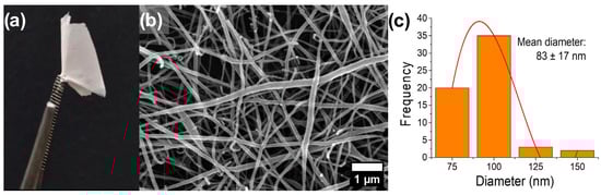
Figure 1.
(a) PVA/CTS nanofiber mats, (b) FESEM micrograph of PVA/CTS nanofibers taken at 20,000×, and (c) histogram of diameter distribution.
3.1.6. ITO–Glass Electrode Surface Modification by Deposition of PVA/CTS Nanofibers
Afterwards, the electrospinning of PVA/CTS (1.5:1 v/v) solutions was carried out using the ITO–glass as the electrospinning collector, replacing the stainless-steel collector, at the electrospinning parameters standardized for the latter, paying special attention to maintaining the RH between 20 and 40%. This resulted in an effective strategy to improve the microstructural quality of nanofibers deposited on the ITO collector, as shown in Figure 2.
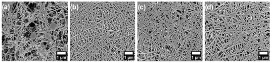
Figure 2.
FESEM micrographs, taken at 10,000×, of electrospun nanofibers on an ITO–glass collector with a relative humidity percent ranging from 20 to 40%, obtained at (a) 8, (b) 12, (c) 16, and (d) 24 h processing times.
Different assays were performed at 8, 12, 16, and 24 h; and 12 h was selected as the optimal processing time for nanofibers production, as it yielded higher fibers compared to the other processing times. The ITO–glass was used as the electrospinning collector because it subsequently serves as the electrode in the electropolymerization/deposition process for the electropolymerization/deposition of PPy:HA on its surface. The CP is deposited by adopting the microstructure and spatial arrangement of the PVA/CTS nanofibers.
On the other hand, the electropolymerization of PPy:HA on PVA/CTS electrospun nanofibers deposited on ITO–glass was performed in ACN. Therefore, it is important to ensure that the microstructure is maintained in this solvent during and after the process. Thus, the fibers were submerged in ACN for 30 min to evaluate their stability after contact with this solvent. Figure S5 shows that the nanoarchitecture is preserved when the fibers are in contact with ACN.
The solubility of the nanofiber mats was also evaluated in H2O, MeOH, EtOH, and in physiological media. The fibers were soluble in all these solvents, which was likely due to their polarity. However, it was necessary to produce water-insoluble nanofiber mats, as their application under aqueous conditions, critical for scaffold use, would otherwise be compromised. To achieve this, nanofiber mats deposited on the ITO electrode were thermally crosslinked at 140 °C for 40 min [35]. After this process, the nanofibers became water insoluble and kept their microstructure after exposure to water for up to 12 h, as shown in Figure 3. The histograms in this figure show a decrease in nanofiber diameter after thermal crosslinking, consistent with previous reports of PVA/CTS electrospun nanofibers, which attribute this effect to the nanofibers’ dehydration [36].
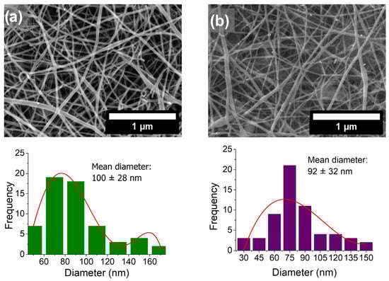
Figure 3.
FESEM micrographs, taken at 10,000×, of PVA/CTS electrospun nanofibers deposited on ITO electrode (a) before and (b) after thermal crosslinking and 48 h immersion in water. The corresponding diameter histograms are shown below each image.
CTS has NH2 and OH groups, while PVA is rich in OH groups, and when heating these blends, hydrogen bond formation between these groups is promoted [35,37], i.e., -OH and NH2 groups of PVA and CTS dehydrated nanofiber films interact by both inter- and intra-molecular crosslinking via hydrogen bonds [35]. Also, some C=O groups can participate in hydrogen bonds forming by interacting with -OH and -NH2 groups [37].
The thermal crosslinking of CTS and PVA blends involves hydrogen bonding and physical entanglement, creating stable networks with enhanced mechanical strength and reduced water solubility [35,37]. In essence, heating the CS/PVA blend encourages molecular interactions, forming a robust network. In addition, thermally crosslinked scaffolds facilitate cell attachment and proliferation and enhance biostability, making them more durable for biomedical use while remaining stable in a physiological environment [38,39].
3.2. FTIR Characterization of PVA/CTS Electrospun Nanofibers
FTIR spectroscopy was used to assess the chemical structure of PVA/CTS nanofibers and interactions between components. PVA, CTS and PVA/CTS electrospun nanofibers spectra are shown in Figure 4. The characteristic vibrations of the main functional groups of PVA and CTS, deeply discussed in previous works [31,40,41,42], are disclosed. The -OH and -NH2 vibrations of CTS are well defined at 3376 cm−1 and 3300 cm−1, respectively, while stretching vibrations of -OH groups of PVA are present at 3321 cm−1. These vibrations overlap between 3200 and 3500 cm−1 in PVA/CTS nanofibers spectrum, showing a broader band compared to those of individual components at 3311 cm−1. This wide signal is indicative of the intra- and inter-molecular hydrogen bonding. It is remarkably shifted to lower wavenumbers and reduced in intensity, considering it a signal of the interactions between the PVA and CTS chains due to the formation of extensive intermolecular hydrogen bonds as previously reported in several works related to PVA/CTS blends [31,42,43].
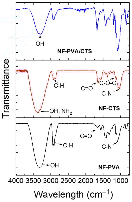
Figure 4.
FTIR spectra of PVA/CTS crosslinked nanofibers and pristine polymers nanofibers prepared as previously reported in [27,44].
The interaction via hydrogen bonding between the C=O and -NH2 groups of CTS and the -OH groups of PVA is also evidenced by shifts in the vibration peaks between 1590 and 1710 cm−1 [27].
3.3. DSC Characterization of PVA/CTS Electrospun Nanofibers
The thermograms for PVA, CTS and PVA/CTS nanofibers are shown in Figure 5. CTS exhibits an initial thermal event below 100 °C, which is related to the loss of bound water. Meanwhile, a second exotherm appears at 297 °C, due to thermal degradation of the CTS, the splitting of glycosidic bonds, and the release of acetylated and deacetylated units [45]. PVA also presents a loss of linking water below 100 °C, followed by a second thermal event at about 229 °C, which is related to the melting of the crystalline domains. Finally, the thermal degradation of the polymer can be observed through an endothermic peak at 280 °C [46].
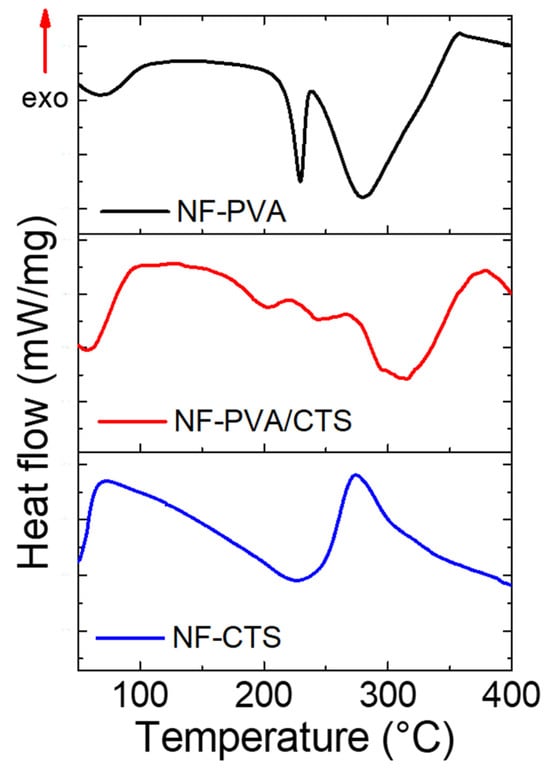
Figure 5.
DSC thermogram for PVA, CTS, and PVA/CTS nanofibers.
The PVA/CTS blend unfolds an evident increase in decomposition temperature compared to pure polymers, around 320 °C, while the melting temperature of the PVA/CTS blend shifts to 202 °C, 27 °C lower than pristine PVA, indicating a less orderly structure. When other components are mixed with PVA, its thermal behavior changes due to new molecular interactions that affect the mobility of the PVA chains and the crystalline structure [47,48,49]. A shift in the PVA–DSC crystalline peak to lower temperatures, as observed here, is a well-documented indicator of interactions, such as hydrogen bonding, between PVA and other components [36,40,41]. The resulting network constituted by hydrogen bonds due to crosslinking restricts polymer chain movement, increasing the melting point of the blend and boosting thermal stability. These results support the FTIR discussion related to the formation of hydrogen bonds between PVA and CTS induced by thermal crosslinking.
3.4. Electrochemical Functionalization of PPy:HA on PVA/CTS Electrospun Nanofibers
3.4.1. Analysis of Suitable Electropolymerization/Deposition Conditions Using ClO4 as Dopant
To establish suitable conditions for the electropolymerization/deposition of PPy:HA on the ITO electrode surface modified with PVA/CTS nanofibers, a PPy film doped with ClO4 was first electropolymerized on a modified ITO electrode as a control. This was performed by using the three-electrode standard configuration, following the potentiodynamic protocol and monitoring through cyclic voltammetry. The successful electropolymerization/deposition of PPy:ClO4 is demonstrated in Figure 6a by comparing the naked ITO electrode and the modified ITO electrode after the electrochemical processes, which are covered by a dark brown thin film. The corresponding cyclic voltammograms are shown in Figure 6b, exhibiting the redox character of PPy, which is not affected by the presence of PVA/CTS nanofibers. It is worth noting that both the reduction and oxidation potential values do not present significant shifts with respect to the construction of PPy:ClO4 obtained in the naked ITO electrode and shown in Figure 6c. Notably, the current density increases after each polymerization cycle, which translates as the growth of the PPy polymer chain on the surface of the PVA/CTS template. However, the electropolymerization rate decreases on modified ITO because of the presence of NF-PVA/CTS.
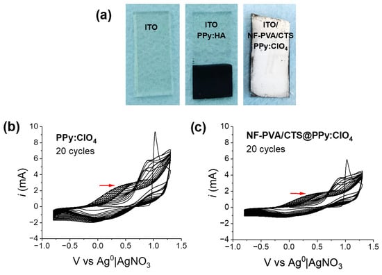
Figure 6.
(a) Digital photos of naked ITO electrode and modified ITO electrode covered with PPy:ClO4, and voltammogram of electropolimerization/deposition of PPy (using ClO4- as dopant) on (b) naked ITO electrode and (c) NF-PVA/CTS modified ITO electrode produced at −0.8 to 1.3 V vs. Ag0|AgNO3, 0.5 V/s.
3.4.2. Electropolymerization/Deposition PPy:HA on PVA/CTS Nanofibers
The optimal concentration of Py for PPy electropolymerization was first determined. Solutions of 5, 8, and 10 mM Py were tested, using 0.1 M TBAP in ACN as dopant and 25 cycles of polymerization. The resulting voltammograms are shown in Figure S6. From these assays, an undefined redox behavior was observed when using the 5 mM concentration, while the 8 mM concentration of Py presented a better defined cyclic voltammogram, disclosing more defined redox kinetics. Therefore, this concentration was chosen to perform further experiments.
In addition, to incorporate HA as a dopant agent, an aqueous solution of HA (0.16 mg/mL) was initially prepared [9]. To improve HA solubility in the reaction medium, a water/ACN mixture (75:25 v/v) was used, allowing the incorporation of HA in the electrochemical process without interfering with the electropolymerization of PPy. It is important to note that for an improved incorporation of HA into the working solution, the dissolution was sonicated for 1 h prior to use in the process.
With the working solution containing Py, TBAP, and HA, the electropolymerization was performed through 50 cycles of potentiodynamic electrodeposition. However, FESEM analysis revealed the formation of a thin PPy:HA film deposited on the surface, which completely covers the microstructure of PVA/CTS nanofibers (Figure 7b). Therefore, the number of electrodeposition cycles was reduced to 15, thereby preserving the nanofiber microarchitecture, as shown in Figure 7c. The voltammograms of both processes (at 50 and 15 cycles) showed a constant oxidation-reduction wave indicative of PPy polymerization. However, significant morphology variations, in secondary morphology, occurred through the electrochemical deposition, as can be observed in Figure 7d,e. As it is shown, the number of electropolymerization cycles used is very important to maintain the nanofibers’ guided microstructure of the PPy:HA deposition. Based on these results, 15 cycles of electropolymerization/deposition were selected to perform further experiments.
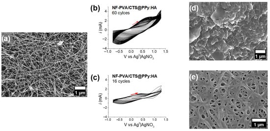
Figure 7.
(a) FESEM microstructure taken at 5000× of PVA/CTS nanofibers before electropolymerization. Cyclic voltammograms of potentiodynamic polymerization of PPy:HA on PVA/CTS modified ITO throughout (b) 50 cycles and (c) 15 cycles at −0.8 to 1.3 V vs. Ag0|AgNO3, 0.5 V/s. FESEM microstructure observed at 5000× of electrochemical deposition of PPy:HA coating after (d) 50 cycles and (e) 15 cycles.
Afterwards, PPy was electropolymerized using HA as a bio-dopant on the surface of modified ITO electrodes that had been previously subjected to thermal crosslinking. The process was carried out with a 0 V starting potential, a superior and inferior vortex of 1.3 and −0.8 V, respectively, a sweep speed of 0.05, a zero final potential, and 0.0035 intervals over 15 cycles. TBAP was used as a support electrolyte to facilitate the electropolymerization process, which were conditions previously standardized for the crafting of CPs coatings on modified ITO electrodes [27]. The voltammogram of this process is shown in Figure 8a, where an increase in the current density to 1.3 V indicates the growth of polymer chains on the surface of PVA/CTS nanofibers deposited on the ITO electrode. The shape of the cyclic voltammogram indicates the electrochemical reversibility characteristic of the PPy matrix. As shown in Figure 8, the electrochemical parameters applied to this process allow the preservation of the microstructure of PVA/CTS nanofibers with a slight increase in nanofiber diameters (Figure 8b) compared to PVA/CTS nanofibers before being subjected to electropolymerization (Figure 8c).
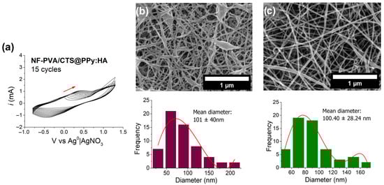
Figure 8.
(a) Voltammogram of the electropolymerization/deposition of PPy:HA on the surface of the ITO electrode surface modified with PVA/CTS nanofibers produced at −0.8 to 1.3 V vs. Ag0|AgNO3, 0.5 V/s; FESEM image at 20,000× and histogram of (b) [NF-PVA/CTS]PPy:HA composite and (c) NF-PVA/CTS.
3.4.3. Electrochemical Characterization of NF-PVA/CTS@PPy:HA Materials
The final material was electrochemically characterized through 50 cycles of cyclic voltammetry. The cyclic voltammograms of PPy:ClO4, NF-PVA/CTS@PPy:ClO4 and NF-PVA/CTS@PPy:HA materials, shown in Figure 9a–c, respectively, present the characteristic oxidation-reduction behavior on PPy either electrodeposited on naked and NF-PVA/CTS-modified ITO electrodes. An evident modification in the quasi-reversible shape of the cyclic voltametric curve can be appreciated because of the presence of NF-CTS/PVA coating (Figure 9b), indicating a decrease in capacitance in comparison to PPy:ClO4. Furthermore, the electrochemical doping with the biomolecule HA significantly reduced the redox reversibility of PPy (Figure 9c). The detriment of the capacity to undergo redox interconversion can be attributed to the presence of HA− species, which are less capable of supporting the redox transition; a similar trend has been observed in the presence of other biomolecules such as glucose and CTS [50,51,52,53].
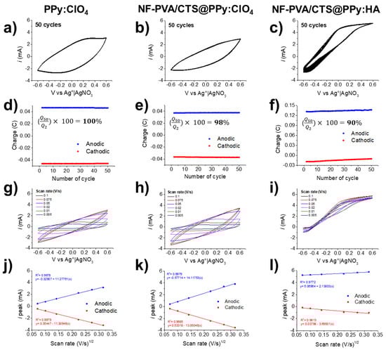
Figure 9.
Electrochemical characterization of PPy:ClO4, NF-PVA/CTS@PPy:ClO4 and NF-PVA/CTS@PPy:HA through cyclic voltammetry in TBAP 0.1 M in ACN at −0.6 to 0.6 V vs. Ag0|AgNO3, 0.5 V/s (a–c), analysis of charge stability (d–f), influence of scan rate (g–i), and linear dependence ipeak at different scan rates (j–l).
In accordance, a constant charge capacity can be observed in PPy:ClO4 (Figure 9d) and in composite NF-PVA/CTS/PPy:ClO4 (Figure 9e) over 50 cycles of voltammetry; in comparison, PPy:ClO4 displayed a charge capacity 1.25 times higher than NF-CTS/PVA@PPy:ClO4. Meanwhile, the bio-doped NF-CTS/PVA@PPy:HA composite exhibited a decrease in charge through the 50 cycles of CV, reaching a charge 1.04 times higher at the 2nd cycle than that at the 50th cycle. However, the electrochemical stability in the three composites resulted in ≥90%, demonstrating a strong adhesion of PPy-based coatings, projecting their potential for electrostimulation.
Scan rate variations, during the cyclic voltammetry, were applied to analyze the relationship between the scan rate and current (ipeak), and the resulting comparative cyclic voltammograms are presented in Figure 9g–i. A linear correlation between ipeak versus the square root of the scan rate ((V/s)1/2), presented in Figure 9j,k, allows inferring that the electron transfer is governed by diffusing species [51,54]. In contrast, NF-PVA/CTS@PPy:HA (Figure 9l) presented a slightly curved shape after HA doping, indicating non-reversible electron transfer. In accordance, the ratio of reductive and oxidative peak currents (ired/iox) depicted in Figure S7 is close to 1 for PPy:ClO4 and NF-PVA/CTS@PPy:ClO4, indicating high reversibility. However, the ired/iox ratio of NF-PVA/CTS@PPy:HA suggests that the electron transfer occurs in an irreversible way [55,56,57].
3.5. Biological Evaluation of NF-PVA/CTS@PPy:HA
The biocompatibility of NF-PVA/CTS-based scaffolds was evaluated using an indirect cell viability assay and a wound-healing protocol in 3T3-L1 and NIH-3T3 fibroblasts. The results are presented in Figure 10. Composites were evaluated using the resazurin reduction assay and MTT in accordance with ISO 10993 for medical devices [58,59].
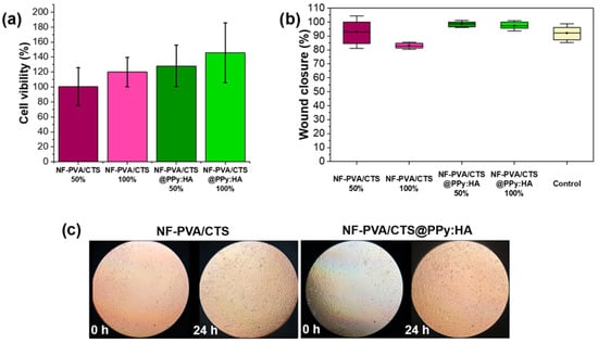
Figure 10.
Comparative results of biological evaluation in NIH-3T3 fibroblasts: (a) cell viability (ANOVA F = 0.414, p = 0.748, α = 0.05) and (b) wound healing of NF-PVA/CTS and NF-PVA/CTS@PPy:HA (ANOVA F = 3.418, p = 0.073, α = 0.05); (c) micrographs of the wound-healing process aided by the NF-PVA/CTS-based composites.
The cytotoxicity of NF-PVA/CTS-based scaffolds was evaluated using an indirect assay and a wound-healing protocol in NIH-3T3 fibroblasts. The results are presented in Figure 10. Composites were evaluated using the MTT assay in accordance with ISO 10993 for medical devices [59]. Cell viability must be superior to 70% at 4 × 10³ cells per well (100%) and at 2 × 10³ cells per well (50%). Electro-responsive scaffolds reached cell viability of 128.1 ± 27.8% and 145.7 ± 39.8% at 50% and 100% of composite media, respectively (Figure 10a). No differences were observed between the control membrane and the PPy:HA ones, in viability or morphology (Figure 10c), indicating the potential application of the hybrid substrate for tissue engineering.
Furthermore, the wound-healing approach shows comparable behavior between NF-PVA/CTS and the hybrid scaffold NF-PVA/CTS@PPy:HA at 24 h of cell culture (Figure 10b,c). It can be inferred that the electrodeposition of PPy:HA coating does not present an adverse effect to compromise the wound-healing rate; from 0 to 24 h, cell migration permitted the effective wound closure (Figure 10c). The electro-responsive scaffold media-exposed cells demonstrated wound-healing capacities of 98.6 ± 1.4% and 97.2 ± 1.9% for 50% and 100% of the media concentration, respectively.
According to the resazurin reduction assay, after 14 days of culture, pristine NF-PVA/CTS scaffolds supported an average of 18,270 ± 10,500 cells, whereas NF-PVA/CTS@PPy:HA scaffolds yielded an average of 25,760 ± 129 cells (Figure 11). These results highlight the hybrid scaffold’s biocompatibility and its promising potential for tissue engineering applications.
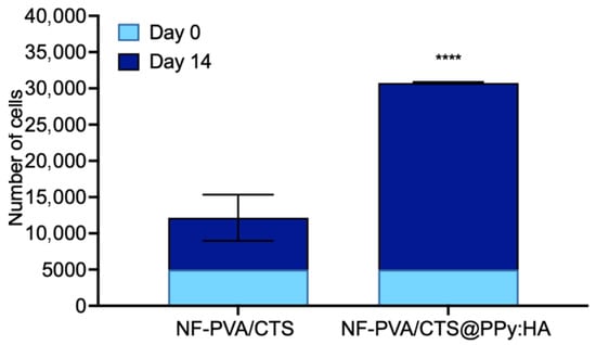
Figure 11.
Comparative results of biological evaluation in 3T3-L1 fibroblasts: number of cells at day 0 and 14 for each composite, and micrographs of the wound-healing process aided by the NF-PVA/CTS-based composites. Results are presented as the mean ± SD (n = 3). **** p < 0.001 using two-way ANOVA with Dunnett’s multiple comparisons test.
For comparison, PPy/PCL fibrous composites have previously been reported to support 93.4% cell viability in NIH-3T3 cells and to promote 46% in vivo wound closure 7 days post-surgery [60]. Similarly, CTS/cellulose-based fibrous composites containing 5 to 10% PPy exhibited relative cell viability values of up to 1.0 (well above the ISO 10993-5 cytotoxicity threshold of 0.7) and wound closure rates ranging from 41 to 58% depending on PPy content [61].
4. Conclusions
PVA/CTS nanofibers deposited on ITO electrodes serve as an excellent template for the electropolymerization/deposition of PPy doped with HA, yielding an advanced composite biomaterial. The ITO glass is an excellent electrospinning collector, which later serves as an electrochemical electrode. The control of relative humidity is a key parameter for the successful production of high-quality PVA/CTS nanofibers.
The PVA/CTS composite fibers provided a suitable matrix for the electrochemical deposition of PPy coatings. The modification of ITO electrodes via electrospinning stands out as an excellent alternative for guiding the deposition and growth of PPy coatings, facilitating the crafting of electro-responsive microarrangements with high porosity and interconnectivity. The incorporation of HA as a bioactive dopant significantly affects the redox and capacitive features of PPy in contrast to PPy:ClO4. However, capacitive behavior is not implied within the context of electro-responsive scaffolding materials. Although the reversible redox response decreased after incorporating HA into the PPy matrix, the electrochemical stability of NF-PVA/CTS@PPy:HA stands out, reaching 90% after 50 scans of cyclic voltammetry.
Regarding cell culture performance, the nanostructured NF-PVA/CTS@PPy:HA composites demonstrate promising potential for biomedical applications, with a cell viability of 145.7 ± 39.8% in NIH-3T3 fibroblasts, as determined by the MTT assay. After 14 days of cell culture, 3T3-L1 fibroblast cells reached 30,000 cells. The wound closure capacity reached 97.2 ± 1.9% at 24 h in NIH-3T3 fibroblasts. These results indicate that the material is non-cytotoxic, does not alter cell morphology, and has no adverse effects on cell migration.
Supplementary Materials
The following supporting information can be downloaded at https://www.mdpi.com/article/10.3390/jcs10010057/s1, Figure S1: FE-SEM micrographs, at 10,000×, of samples obtained at voltages of 10, 12, and 14 kV; Figure S2: FE-SEM micrographs, at 5000×, of samples obtained at flow rates of 0.1, 0.3, and 0.5 mL/h; Figure S3: FE-SEM micrographs, at 10,000×, of samples obtained at needle-to-collector distances of 15, 17.5, and 20 cm; Figure S4: FE-SEM micrographs, at 10,000×, of samples obtained from CTS dissolved in 70:30, 80:20, and 90:10 AA/H2O v/v mixtures; Figure S5: FE-SEM micrographs, at 20,000×, of electrospun nanofibers before and after soaking in ACN for 30 min; Figure S6: Cyclic voltammograms of PPy electropolymerization using 5, 8, and 10 mM pyrrole with TBAP 0.1 M in ACN, and comparison of the three concentrations; Figure S7: Comparative i_red/i_ox ratios at variable scan rates for PPy:ClO4, NF-PVA/CTS@PPy:ClO4, and NF-PVA/CTS@PPy:HA.
Author Contributions
Conceptualization, R.L.Q.-O., A.P.-N., C.G.-M., K.J.-M., B.A.F.-U., L.M.B.-A. and J.B.G.-C.; methodology, R.L.Q.-O., A.P.-N., C.G.-M., K.J.-M., B.A.F.-U., L.M.B.-A., J.M.P.-O., C.R.-M. and J.B.G.-C.; software, R.L.Q.-O., A.P.-N., C.G.-M., K.J.-M., B.A.F.-U., L.M.B.-A., J.M.P.-O., C.R.-M. and J.B.G.-C.; validation, R.L.Q.-O., A.P.-N., C.G.-M., K.J.-M., B.A.F.-U., L.M.B.-A. and J.B.G.-C.; formal analysis, R.L.Q.-O., A.P.-N., C.G.-M., K.J.-M., B.A.F.-U., L.M.B.-A., J.M.P.-O., C.R.-M. and J.B.G.-C.; investigation, R.L.Q.-O., A.P.-N., C.G.-M., K.J.-M., B.A.F.-U., L.M.B.-A., J.M.P.-O., C.R.-M. and J.B.G.-C.; resources, R.L.Q.-O., A.P.-N., C.G.-M., K.J.-M., B.A.F.-U., L.M.B.-A. and J.B.G.-C.; data curation, R.L.Q.-O., A.P.-N., C.G.-M., K.J.-M., B.A.F.-U., L.M.B.-A., J.M.P.-O., C.R.-M. and J.B.G.-C.; writing—original draft preparation, R.L.Q.-O., A.P.-N., C.G.-M., K.J.-M., B.A.F.-U., L.M.B.-A., J.M.P.-O., C.R.-M. and J.B.G.-C.; writing—review and editing, R.L.Q.-O., A.P.-N., C.G.-M., K.J.-M., B.A.F.-U., L.M.B.-A., J.M.P.-O., C.R.-M. and J.B.G.-C.; visualization, R.L.Q.-O., A.P.-N., C.G.-M., K.J.-M., B.A.F.-U., L.M.B.-A., J.M.P.-O., C.R.-M. and J.B.G.-C.; supervision, J.B.G.-C.; project administration, R.L.Q.-O., A.P.-N., C.G.-M., K.J.-M., B.A.F.-U., L.M.B.-A., J.M.P.-O., C.R.-M. and J.B.G.-C.; funding acquisition, J.B.G.-C. All authors have read and agreed to the published version of the manuscript.
Funding
This research received no external funding.
Data Availability Statement
The raw data supporting the conclusions of this article will be made available by the authors on request.
Acknowledgments
The authors acknowledge the financial support from the Secretaría de Ciencia, Humanidades, Tecnología e Innovación(SECIHTI, Mexico) and CIC-UMSNH. A.P.N. acknowledges the Postdoctoral Fellowship (CVU 593576).
Conflicts of Interest
The authors declare no conflicts of interest.
Abbreviations
The following abbreviations are used in this manuscript:
| ECM | Extracellular matrix |
| CTS | Chitosan |
| PVA | Polyvinyl alcohol |
| CPs | Conductive polymers |
| PPy | Polypyrrole |
| HA | Hyaluronic acid |
| AcOH | Acetic acid |
References
- Alegret, N.; Dominguez-Alfaro, A.; Mecerreyes, D. 3D Scaffolds Based on Conductive Polymers for Biomedical Applications. Biomacromolecules 2019, 20, 73–89. [Google Scholar] [CrossRef]
- Marsudi, M.A.; Ariski, R.T.; Wibowo, A.; Cooper, G.; Barlian, A.; Rachmantyo, R.; Bartolo, P.J. Conductive Polymeric-Based Electroactive Scaffolds for Tissue Engineering Applications: Current Progress and Challenges from Biomaterials and Manufacturing Perspectives. Int. J. Mol. Sci. 2021, 22, 11543. [Google Scholar] [CrossRef]
- Massoumi, B.; Abbasian, M.; Khalilzadeh, B.; Jahanban-Esfahlan, R.; Samadian, H.; Derakhshankhah, H.; Jaymand, M. Electrically Conductive Nanofibers Composed of Chitosan-Grafted Polythiophene and Poly(ε-caprolactone) as Tissue Engineering Scaffold. Fibers Polym. 2021, 22, 49–58. [Google Scholar] [CrossRef]
- Dixon, D.T.; Gomillion, C.T. Conductive Scaffolds for Bone Tissue Engineering: Current State and Future Outlook. J. Funct. Biomater. 2022, 13, 1. [Google Scholar] [CrossRef]
- Khan, M.A.; Cantù, E.; Tonello, S.; Serpelloni, M.; Lopomo, N.F.; Sardini, E. A Review on Biomaterials for 3D Conductive Scaffolds for Stimulating and Monitoring Cellular Activities. Appl. Sci. 2019, 9, 961. [Google Scholar] [CrossRef]
- Wang, X.X.; Yu, G.F.; Zhang, J.; Yu, M.; Ramakrishna, S.; Long, Y.Z. Conductive Polymer Ultrafine Fibers via Electrospinning: Preparation, Physical Properties and Applications. Prog. Mater. Sci. 2021, 115, 100704. [Google Scholar] [CrossRef]
- Nezakati, T.; Seifalian, A.; Tan, A.; Seifalian, A.M. Conductive Polymers: Opportunities and Challenges in Biomedical Applications. Chem. Rev. 2018, 118, 6766–6843. [Google Scholar] [CrossRef]
- Pang, A.L.; Arsad, A.; Ahmadipour, M. Synthesis and Factors Affecting the Conductivity of Polypyrrole: A Short Review. Polym. Adv. Technol. 2021, 32, 1428–1454. [Google Scholar] [CrossRef]
- Kim, S.; Jang, Y.; Jang, M.; Lim, A.; Hardy, J.G.; Park, H.S.; Lee, J.Y. Versatile Biomimetic Conductive Polypyrrole Films Doped with Hyaluronic Acid of Different Molecular Weights. Acta Biomater. 2018, 80, 258–268. [Google Scholar] [CrossRef] [PubMed]
- Acosta, M.; Santiago, M.D.; Irvin, J.A. Electrospun Conducting Polymers: Approaches and Applications. Materials 2022, 15, 8820. [Google Scholar] [CrossRef]
- Liang, Y.; Goh, J.C.H. Polypyrrole-Incorporated Conducting Constructs for Tissue Engineering Applications: A Review. Bioelectricity 2020, 2, 101–119. [Google Scholar] [CrossRef] [PubMed]
- Zhou, C.; Liu, Z.; Yan, Y.; Du, X.; Mai, Y.W.; Ringer, S. Electro-Synthesis of Novel Nanostructured PEDOT Films and Their Application as Catalyst Support. Nanoscale Res. Lett. 2011, 6, 364. [Google Scholar] [CrossRef] [PubMed]
- Anisiei, A.; Andreica, B.I.; Rosca, I. Binary Chitosan/Quaternized Chitosan via Electrospinning: Morphology and Antimicrobial Activity. Cellulose Chem. Technol. 2024, 58, 21–29. [Google Scholar] [CrossRef]
- El-Araby, A.; Janati, W.; Ullah, R.; Ercisli, S.; Errachidi, F. Chitosan, Chitosan Derivatives, and Chitosan-Based Nanocomposites: Eco-Friendly Materials for Advanced Applications (A Review). Front. Chem. 2023, 11, 1327426. [Google Scholar] [CrossRef]
- Taokaew, S.; Chuenkaek, T. Developments of Core/Shell Chitosan-Based Nanofibers by Electrospinning Techniques: A Review. Fibers 2024, 12, 26. [Google Scholar] [CrossRef]
- Ignatova, M.; Manolova, N.; Rashkov, I. Electrospun Antibacterial Chitosan-Based Fibers. Macromol. Biosci. 2013, 13, 860–872. [Google Scholar] [CrossRef]
- Zhang, X.; Wang, Y.; Gao, Z.; Mao, X.; Cheng, J.; Huang, L.; Tang, J. Advances in Wound Dressing Based on Electrospinning Nanofibers. J. Appl. Polym. Sci. 2024, 141, e54746. [Google Scholar] [CrossRef]
- Rivera-Hernández, G.; Antunes-Ricardo, M.; Martínez-Morales, P.; Sánchez, M.L. Polyvinyl Alcohol-Based Drug Delivery Systems for Cancer Treatment. Int. J. Pharm. 2021, 600, 120478. [Google Scholar] [CrossRef]
- Vu, T.H.N.; Morozkina, S.N.; Uspenskaya, M.V. Study of the Nanofibers Fabrication Conditions from the Mixture of Poly(vinyl alcohol) and Chitosan by Electrospinning Method. Polymers 2022, 14, 811. [Google Scholar] [CrossRef]
- Mombini, S.; Mohammadnejad, J.; Bakhshandeh, B.; Narmani, A.; Nourmohammadi, J.; Vahdat, S.; Zirak, S. Chitosan–PVA–CNT Nanofibers as Electrically Conductive Scaffolds for Cardiovascular Tissue Engineering. Int. J. Biol. Macromol. 2019, 140, 278–287. [Google Scholar] [CrossRef]
- Abedi, A.; Bakhshandeh, B.; Babaie, A.; Mohammadnejad, J.; Vahdat, S.; Mombeiny, R.; Moosavi, S.R.; Amini, J.; Tayebi, L. Concurrent Application of Conductive Biopolymeric Chitosan/Polyvinyl Alcohol/MWCNTs Nanofibers, Intracellular Signaling Manipulating Molecules, and Electrical Stimulation for More Effective Cardiac Tissue Engineering. Mater. Chem. Phys. 2021, 258, 123842. [Google Scholar] [CrossRef]
- Li, T.T.; Yan, M.; Zhong, Y.; Ren, H.T.; Lou, C.W.; Huang, S.Y.; Lin, J.H. Processing and Characterizations of Rotary Linear Needleless Electrospun Polyvinyl Alcohol (PVA)/Chitosan (CS)/Graphene (Gr) Nanofibrous Membranes. J. Mater. Res. Technol. 2019, 8, 5124–5132. [Google Scholar] [CrossRef]
- Kiristi, M.; Oksuz, A.U.; Oksuz, L.; Ulusoy, S. Electrospun Chitosan/PEDOT Nanofibers. Mater. Sci. Eng. C 2013, 33, 3845–3850. [Google Scholar] [CrossRef]
- Karim, M.R. Fabrication of Electrospun Aligned Nanofibers from Conducting Polyaniline Copolymer/Polyvinyl Alcohol/Chitosan Oligosaccharide in Aqueous Solutions. Synth. Met. 2013, 178, 34–37. [Google Scholar] [CrossRef]
- Bagheri, B.; Zarrintaj, P.; Samadi, A.; Zarrintaj, R.; Ganjali, M.R.; Saeb, M.R.; Mozafari, M.; Park, O.O.; Kim, Y.C. Tissue Engineering with Electrospun Electro-Responsive Chitosan–Aniline Oligomer/Polyvinyl Alcohol. Int. J. Biol. Macromol. 2020, 147, 160–169. [Google Scholar] [CrossRef]
- Zarei, M.; Samimi, A.; Khorram, M.; Abdi, M.M.; Golestaneh, S.I. Fabrication and Characterization of Conductive Polypyrrole/Chitosan/Collagen Electrospun Nanofiber Scaffold for Tissue Engineering Application. Int. J. Biol. Macromol. 2021, 168, 175–186. [Google Scholar] [CrossRef] [PubMed]
- Pérez-Nava, A.; Hernández-Acosta, I.; González-Campos, J.B.; Frontana-Uribe, B.A. Conductive Polymer Coatings on PVA Electrospun Nanofibers by Electrochemical Polymerization/Deposition toward Improved Mechanical Performance. Prog. Org. Coat. 2025, 201, 109105. [Google Scholar] [CrossRef]
- Suarez-Arnedo, A.; Figueroa, F.T.; Clavijo, C.; Arbeláez, P.; Cruz, J.C.; Muñoz-Camargo, C. An ImageJ Plugin for the High-Throughput Image Analysis of In Vitro Scratch Wound Healing Assays. PLoS ONE 2020, 15, e0232565. [Google Scholar] [CrossRef]
- Radstake, W.E.; Gautam, K.; Van Rompay, C.; Vermeesen, R.; Tabury, K.; Verslegers, M.; Baatout, S.; Baselet, B. Comparison of In Vitro Scratch Wound Assay Experimental Procedures. Biochem. Biophys. Rep. 2023, 33, 101423. [Google Scholar] [CrossRef]
- Kulczyńska, J.; Chibrikov, V.; Pawcenis, D.; Jędrzejczyk, R.; Sebastian, V.; Cybulska, J.; Zdunek, A.; Kyzioł, A. Sustainable poly(vinyl alcohol)/chitosan electrospun nanofibers and casted films with bioactive additives—Comparative study on physicochemical properties and in vitro biological activity. Ind. Crop. Prod. 2025, 233, 121335. [Google Scholar] [CrossRef]
- Mata, G.C.d.; Morais, M.S.; Oliveira, W.P.d.; Aguiar, M.L. Composition Effects on the Morphology of PVA/Chitosan Electrospun Nanofibers. Polymers 2022, 14, 4856. [Google Scholar] [CrossRef]
- Mirzaeei, S.; Taghe, S.; Asare-Addo, K.; Nokhodchi, A. Polyvinyl Alcohol/Chitosan Single-Layered and Polyvinyl Alcohol/Chitosan/Eudragit RL100 Multi-layered Electrospun Nanofibers as an Ocular Matrix for the Controlled Release of Ofloxacin: An In Vitro and In Vivo Evaluation. AAPS PharmSciTech 2021, 22, 170. [Google Scholar] [CrossRef]
- Vu, T.H.N.; Morozkina, S.N.; Olekhnovich, R.O.; Podshivalov, A.V.; Uspenskaya, M.V. Study on Fabrication and Properties of Polyvinyl Alcohol/Chitosan Nanofibers Created from Aqueous Solution with Acetic Acid and Ethanol by the Electrospinning Method. Polymers 2024, 16, 3393. [Google Scholar] [CrossRef]
- Pelipenko, J.; Kristl, J.; Janković, B.; Baumgartner, S.; Kocbek, P. The impact of relative humidity during electrospinning on the morphology and mechanical properties of nanofibers. Int. J. Pharm. 2013, 456, 125–134. [Google Scholar] [CrossRef] [PubMed]
- Sau, S.; Pandit, S.; Kundu, S. Crosslinked Poly(vinyl alcohol): Structural, Optical and Mechanical Properties. Surf. Interfaces 2021, 25, 101198. [Google Scholar] [CrossRef]
- Nasikhudin; Diantoro, M.; Kusumaatmaja, A.; Triyana, K. Stabilization of PVA/Chitosan/TiO2 Nanofiber Membrane with Heat Treatment and Glutaraldehyde Crosslink. IOP Conf. Ser. Mater. Sci. Eng. 2018, 367, 012004. [Google Scholar] [CrossRef]
- Buslov, D.K.; Sushko, N.I.; Tretinnikov, O.N. IR Investigation of Hydrogen Bonds in Weakly Hydrated Films of Poly(vinyl alcohol). Polym. Sci. Ser. A 2011, 53, 1121–1127. [Google Scholar] [CrossRef]
- Shamekhia, M.A.; Rabieeb, A.; Mirzadehc, H.; Mahdavia, H.; Mohebbi-Kalhorid, D.; Eslaminejad, M.B. Fabrication and characterization of hydrothermal cross-linked chitosan porous scaffolds for cartilage tissue engineering applications. Mater. Sci. Eng. C 2017, 80, 532–542. [Google Scholar] [CrossRef]
- Park, K.-S.; Lee, E.-G.; Son, Y. Uniaxial cyclic strain stimulates cell proliferation and secretion of interleukin-6 and vascular endothelial growth factor of human dermal fibroblasts seeded on chitosan scaffolds. J. Biomed. Mater. Res. Part A 2014, 102, 2268–2276. [Google Scholar] [CrossRef]
- Gonçalves, R.P.; Ferreira, W.H.; Gouvêa, R.F.; Andrade, C.T. Effect of Chitosan on the Properties of Electrospun Fibers from Mixed Poly(vinyl alcohol)/Chitosan Solutions. Mater. Res. 2017, 20, 984–993. [Google Scholar] [CrossRef]
- Jia, Y.T.; Gong, J.; Gu, X.H.; Kim, H.Y.; Dong, J.; Shen, X.Y. Fabrication and Characterization of Poly(vinyl alcohol)/Chitosan Blend Nanofibers Produced by the Electrospinning Method. Carbohydr. Polym. 2007, 67, 403–409. [Google Scholar] [CrossRef]
- Olvera Bernal, R.A.; Olekhnovich, R.O.; Uspenskaya, M.V. Chitosan/PVA Nanofibers as Potential Material for the Development of Soft Actuators. Polymers 2023, 15, 2037. [Google Scholar] [CrossRef]
- Ahmadijokani, F.; Molavid, H.; Bahib, A.; Wuttkee, S.; Kamkarc, M.; Rojasc, O.J.; Kob, F.; Arjmand, M. Electrospun nanofibers of chitosan/polyvinyl alcohol/UiO-66/ nanodiamond: Versatile adsorbents for wastewater remediation and organic dye removal. Chem. Eng. J. 2023, 457, 141176. [Google Scholar] [CrossRef]
- Pérez-Nava, A.; Reyes-Mercado, E.; González-Campos, J.B. production of chitosan nanofibers using the HFIP/acetic acid mixture as electrospinning solvent. Chem. Eng. Process. Process Intensif. 2022, 173, 108849. [Google Scholar] [CrossRef]
- Delgado-Rangel, L.H.; Huerta-Saquero, A.; Eufracio-García, N.; Meza-Villezcas, A.; Mota-Morales, J.D.; González-Campos, J.B. Deep Eutectic Solvent-Assisted Phase Separation in Chitosan Solutions for the Production of 3D Monoliths and Films with Tailored Porosities. Int. J. Biol. Macromol. 2020, 164, 4084–4094. [Google Scholar] [CrossRef] [PubMed]
- Delgado-Rangel, L.H.; Hernández-Vargas, J.; Becerra-González, M.; Martínez-Torres, A.; Prokhorov, E.; González-Campos, J.B. Development of Collagen/Poly(vinyl alcohol)/Chondroitin Sulfate and Collagen/Poly(vinyl alcohol)/HA Electrospun Scaffolds for Tissue Engineering. Fibers Polym. 2019, 20, 2470–2484. [Google Scholar] [CrossRef]
- Gaaz, T.S.; Sulong, A.B.; Akhtar, M.N.; Kadhum, A.A.H.; Mohamad, A.B.; Al-Amiery, A.A. Properties and Applications of Polyvinyl Alcohol, Halloysite Nanotubes and Their Nanocomposites. Molecules 2015, 20, 22833–22847. [Google Scholar] [CrossRef]
- Gupta, B.; Agarwal, R.; Alam, M.S. Preparation and characterization of polyvinyl alcohol-polyethylene oxide-carboxymethyl cellulose blend membranes. J. Appl. Polym. Sci. 2013, 127, 1301–1308. [Google Scholar] [CrossRef]
- Fong, R.J.; Robertson, A.; Mallon, P.E.; Thompson, R.L. The Impact of Plasticizer and Degree of Hydrolysis on Free Volume of Poly(vinyl alcohol) Films. Polymers 2018, 10, 1036. [Google Scholar] [CrossRef]
- Chen, N.; Zhang, J. The role of hydroge-bonding interaction in poly(vinyl alcohol)/poly(acrylic acid) blending solutions and their films. Chin. J. Polym. Sci. 2010, 28, 903–911. [Google Scholar] [CrossRef]
- Rahmania, F.J.; Imae, T.; Chu, J.P. Electrochemical Nonenzymatic Glucose Sensors Catalyzed by Au Nanoclusters on Metallic Nanotube Arrays and Polypyrrole Nanowires. J. Colloid Interface Sci. 2024, 657, 567–579. [Google Scholar] [CrossRef]
- Thakur, A.; Pal, S.; Sharma, U.; Sharma, A.; Choudhary, M.; Joshi, M.C.; Setiabudi, H.D.; Singh, P.P.; Singh, A.; Shukla, S.K. Advanced TiO2–Polypyrrole Nanostructures Enhance Glucose Detection Accuracy with Cutting-Edge Non-Enzymatic Electrochemical Capabilities. Chem. Phys. Impact 2025, 10, 100818. [Google Scholar] [CrossRef]
- Sukumaran, R.A.; Lakavath, K.; Phani Kumar, V.V.N.; Karingula, S.; Mahato, K.; Kotagiri, Y.G. Eco-Friendly Synthesis of a Porous Reduced Graphene Oxide–Polypyrrole–Gold Nanoparticle Hybrid Nanocomposite for Electrochemical Detection of Methotrexate Using a Strip Sensor. Nanoscale 2024, 17, 4472–4484. [Google Scholar] [CrossRef]
- Kaur, G.; Toppo, A.E.; Garima; Mehta, S.K.; Sharma, S. Synthesis of Polypyrrole (PPy) Functionalized Halloysite Nanotubes (HNTs): An Electrochemical Sensor for Ibuprofen. Appl. Surf. Sci. 2024, 652, 159280. [Google Scholar] [CrossRef]
- Biradar, B.R.; Thathron, N.; Hanchate, A.; Das, P.P.; Mal, S.S. Development of a Cholesterol Biosensor and Energy Storage System Based on Polypyrrole-Coated Polyoxometalate. J. Alloys Compd. 2025, 1016, 178994. [Google Scholar] [CrossRef]
- Kumar, R.; Bag, M. Quantifying Capacitive and Diffusion-Controlled Charge Storage from 3D Bulk to 2D Layered Halide Perovskite-Based Porous Electrodes for Efficient Supercapacitor Applications. J. Phys. Chem. C 2021, 125, 16946–16954. [Google Scholar] [CrossRef]
- Egger, M.; Koehne, I.; Wickenhauser, D.; Schlemmer, W.; Spirk, S.; Pietschnig, R. Electrochemistry and Stability of 1,1′-Ferrocene-Bisphosphonates. ACS Omega 2023, 8, 10899–10905. [Google Scholar] [CrossRef] [PubMed]
- ISO 10993-5:2009; Biological Evaluation of Medical Devices. Part 5: Tests for In Vitro Cytotoxicity. ISO: Geneva, Switzerland, 2009.
- Thangaraju, P.; Varthya, S.B. ISO 10993: Biological Evaluation of Medical Devices. In Medical Device Guidelines and Regulations Handbook; Springer: Cham, Switzerland, 2022. [Google Scholar] [CrossRef]
- Tang, Q.; Ke, Q.; Chen, Q.; Zhang, X.; Su, J.; Ning, C.; Fang, L. Flexible, Breathable, and Self-Powered Patch Assembled from Electrospun Polymer Triboelectric Layers and Polypyrrole-Coated Electrode for Infected Chronic Wound Healing. ACS Appl. Mater. Interfaces 2023, 15, 17641–17652. [Google Scholar] [CrossRef]
- Muchová, M.; Münster, L.; Valášková, K.; Lovecká, L.; Víchová, Z.; Osička, J.; Kašpárková, V.; Humpolíček, P.; Vašíček, O.; Vícha, J. One-Step Fabrication of Chitosan/Dialdehyde Cellulose/Polypyrrole Composite Nanofibers with Antibacterial, Antioxidant, and Immunomodulatory Effects. Int. J. Biol. Macromol. 2025, 308, 142105. [Google Scholar] [CrossRef]
Disclaimer/Publisher’s Note: The statements, opinions and data contained in all publications are solely those of the individual author(s) and contributor(s) and not of MDPI and/or the editor(s). MDPI and/or the editor(s) disclaim responsibility for any injury to people or property resulting from any ideas, methods, instructions or products referred to in the content. |
© 2026 by the authors. Licensee MDPI, Basel, Switzerland. This article is an open access article distributed under the terms and conditions of the Creative Commons Attribution (CC BY) license.