Abstract
The operational ability of a unit or mechanism depends mainly on the quality of the mechanically produced working surfaces. Many materials can be assigned to a group of hard-to-cut materials that includes titanium- and aluminum-based alloys, a new class of heat-resistant alloys, SiCp/Al composites, hard alloys, and other alloys. The difficulties in their machining are related not only to the high temperatures achieved on the contact pads under mechanical load and the extreme cutting conditions but also to the properties of those materials, which affect the adhesion of the chip to the tool faces, hindering chip flow. One of the possible solutions to reduce those effects and improve the operational life of the tool, and as a consequence, the final quality of the working surface of the unit, is texturing the rake face of the tool with microgrooves or nanogrooves, microholes or nanoholes (pits, dimples), micronodes, cross-chevron textures, and other microtextures, the depth of which is in the range of 3.0–200.0 µm. This review is addressed at systematizing the data obtained on micro- and nanotexturing of PCD tools for cutting hard-to-cut materials by different techniques (fiber laser graving, femto- and nanosecond laser, electrical discharge machining, fused ion beam), additionally subjected to fluorination and dip- and drop-based coatings, and the effect created by the use of the textured PCD tool on the machined surface.
1. Introduction
The behavior of engineering parts under exploitation loads depends on several criteria. One important criterion is surface quality, which plays a significant role in the performance and operational life of engineering parts as a part of a mechanism or a unit in machinery, aerospace, the tool industry, electronics, and energy systems. Tribological characterization of surfaces reveals the controlling ability needed to obtain the required functional performance [1,2,3,4,5]. Recently, the tool surface geometry modified by texturing was proposed as a new surface engineering approach, and that is in demand due to its ability to reduce adhesion of the workpiece material and increase lubrication [6,7,8,9].
The geometries of the cutting tools are one of the significant criteria affecting the resulting cutting forces, machined workpiece surface roughness, tool operational life, and the dissimilarity of the chip flow pattern [10]. Microtexturing of cutting tools decreases contact loads and tool wear [11,12,13,14,15], which are related to microtexture’s ability to reduce the friction coefficient, and, therefore, the tribological properties are enhanced [16,17,18,19]. Microholes (so-called micropits or rather microdimples depending on the particular production technology) or microgrooves can be produced with several machining methods, depending on the tool and workpiece material properties, and on the desired microrelief of the cutting tool rake face, such as electrical discharge machining (super drill or with a wire tool electrode) [20,21,22], laser ablation [23,24,25], a fused ion beam [26], and microindention [27].
Electrical discharge machining (EDM) is a machining process that allows the formation of the conductive workpiece through the exposure of electric discharge between the tool electrode and the workpiece [28,29,30,31]. S.T. Kumaran et al. [32] investigated the influence of the µ-EDM process factors on parameters of the formed microholes that were textures on the surface of titanium alloys (TiAlSiZr). The required microholes with different diameters were produced by varying EDM factors. It is found that the single spark energy allows for controlling the dimple diameter, height, width, and aspect ratio. C.M. Rao et al. [33] studied the effect of microhole textures on PCD tools in turning titanium using the minimum quantity lubrication (MQL) technique. The diameter, depth, and orientation of the produced microholes were investigated. Electrical discharge machining was used to produce microholes on the cutting tool’s rake face. It was found that the textured tool combined with MQL enhanced the cutting temperature, surface roughness, and tool wear resistance by 30, 40, and 50%, respectively.
The texturing pattern on the cutting tool rake face is often used as a chipbreaker. Thus, using this type of chipbreaker is a method to control the shape and character of the chip in cutting and to eliminate premature tool failure. P. Fernandez et al. focus on the effects of laser-textured chipbreakers on PCD tools to reduce chip length in turning Ti6Al4V for the aeronautical industry [34]. A groove-type laser-engraved chipbreaker is proposed to improve chip fragmentation and removal. The achieved surface roughness was 1.31 µm, and the mean value of five consecutive maximum heights between the peak and valley was 19.01 µm. Y. Su et al. [35] investigated the anti-friction and anti-adhesion for microtextured PCD tools in machining Ti6Al4V alloy. It was shown that microgrooves tend to reduce friction during cutting, even in the absence of lubrication. The maximum width of the chip is reduced by 23.6% through the production of microgrooves.
The texturing on PCD tools possesses the ability to enhance the cutting speed while prolonging the operational life of the tool; as a result, productivity in turning is increased when the surface roughness on the machined surface is reduced by 20% [36]. X. Wang et al. produced microgrooves with round corners as texturing on PCD by a nanosecond laser. The textured PCD tool was tested in machining SiCp/Al composites and compared with a non-textured PCD tool. The influence of textural parameters such as the distance between textures and the main cutting edge (texture spacing) was the focus of the research. It is demonstrated that the textured PCD tool reduced the anti-adhesion effect based on the chip direction, besides reducing cutting forces, thus enhancing the wear resistance of the cutting tool, and improving surface roughness. The cutting force of the PCD tool was minimal when the distances between the microgroove textures and the main cutting edge were 35–45 µm.
G. Sakthivel et al. [37] investigated textured PCD with lyophobic wettability for turning Al6061 alloy to enhance anti-friction and self-lubrication properties. The experiments were produced in dry conditions. Lyophobic wettability was formed using an amine silane on the textured surface, which was produced on the PCD tool by the ND:YAG laser. The combination of texturing and lyophobic solution significantly improved the cutting tool’s performance.
F. Wu et al. [38] investigated milling SiCp/Al using a textured PCD cutting tool. Tool life, tribological properties, cutting forces, and lubrication mechanisms were under investigation. The tools with grooves, holes (pits, dimples), and hybrids of grooves and patterns were analyzed and compared with non-textured tools. It was demonstrated that the hybrid textured tool yields optimal results compared to other tools. X. Hao et al. [39] studied the turning of Ti6Al4V by three different texture geometries of PCD tools using the MQL technique. The three textured cutting tools were produced by fiber laser and compared with non-textured cutting tools. Then, the textured tools were applied to the composite lyophilic/lyophobic wettability. It is demonstrated that the proposed PCD successfully reduced the cutting forces and coefficient of friction, besides enhancing the tool wear resistance. P. Ghosh et al. [40] investigated the cutting performance, cutting forces, anti-adhesion, and surface roughness of the machining of AL6082 alloy using a micro/nanotextured PCD tool. The fiber laser was used to create a texture pattern on the surface of the cutting tool. A turning operation was used for testing the textured PCD tool. The cutting forces were reduced by 12–23% for the textured tools, and the resulting surface quality was also enhanced. Y. Su et al. [41] studied the ability to create microgrooves and microholes as texturing patterns on PCD tools by a fiber laser. Controlling the laser parameter scanning speed enables reductions in the width, diameter, and depth of texturing.
S. Moeng et al. [42] produce nanotextures on PCD tools by using a fused ion beam for enhancing the cutting performance and tribological properties of the tool. The cutting tool performance was tested in orthogonal cutting with dry conditions using tungsten carbide as the workpiece. The nanotextures successfully enhanced the coefficient of friction by 7–10% in comparison with the non-textured tool.
This review is addressed at systematizing the data obtained in testing PCD tools in cutting hard-to-cut materials, the effect created by the use of the textured PCD tool, by the nature of the material removal technique, and shapes of the textures on the cutting tool rake face. The research object is a cutting tool made of polycrystalline diamond for cutting hard-to-cut materials, such as the following:
- Titanium and aluminum alloys that are adherent to the cutting tool rake face;
- Composite material with an aluminum matrix reinforced with silicon carbide particles (SiCp/Al), which is widely used in the aerospace, optical, and electronics industries for the following:
- ○
- Electronic chip packaging, including for microwave integrated circuits, power modules, and military radio frequency (RF) systems;
- ○
- Satellite component manufacturing.
This material offers advantages such as a high specific strength, low thermal expansion coefficient, excellent thermal conductivity, and corrosion resistance.
A schematic of the review structure is provided in Figure 1.
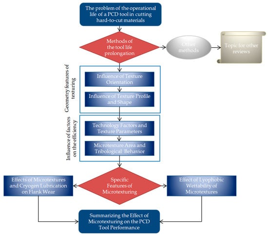
Figure 1.
The schematic of the review structure.
It should be noted that the review does not include factors of the PCD tool, such as the grain size and binder type, which also play an important role in the wear behavior during cutting, since the review is more focused on the effect of microtexturing on the PCD tool. The considered publications also addressed cutting different grades of the materials, and the results cannot be compared and synthesized in absolute terms. However, by comparing results within a single case (particular material, particular PCD tool, microtextures, and production technology), the most efficient trend can be revealed. The relevant data on the influence of PCD tool factors on its performance are published in [43,44,45,46,47,48]. Generally, the smallest (submicron) grit (for example, #3500 corresponds to a grain size of ~5.67 µm) is recommended for precise cutting over the entire cutting distance [49]. The binder of the standard and hard hardness (nickel and nickel–cobalt, respectively) is recommended for precise cutting [50]. The recommended values in machining aluminum-based materials are as follows:
- 10–25 µm is for high-speed machining of silicon–aluminum alloys with a Si content of 12–18% at speeds of 500–1500 m/min.
- 8–9 µm is for machining aluminum alloys with a Si content of less than 12%.
- Submicron is for milling and rough cutting of aluminum alloys with high chipping requirements [51].
In most considered articles, the mentioned PCD tool had a grain size of 10 µm and a cobalt (Co) binder (10–12%) [52]. However, regarding increasing the cobalt content in the binder, it should be noted that the potential thermal degradation of PCD increases when the PCD material degrades at high temperatures above 750 °C, leading to a reduced cutting performance [53,54]. The high wear rate of PCD at these temperatures is due to differences in the rate of thermal expansion between the diamond particles (α = ~1.0 × 10⁻⁶ K−1, which is lower than for other materials [55]) and the binder material (for cobalt, α = ~13 × 10−6 K−1 [56]). Cobalt expands faster than diamond at temperatures above the critical temperature, making the bonds between the diamond particles unstable. The mechanism of thermal degradation is as follows [57]:
- Formation of microcracks in intergrown diamond due to differential expansion at high temperatures;
- Weakening of the bond between diamond grains and the cobalt binder due to interdiffusion of diamond and cobalt at grain boundaries;
- Chemical reaction of diamond with cobalt, converting diamond to graphite, at temperatures above 800 °C.
To improve the thermal stability of PCD, cobalt is leached from the interstitial sites to eliminate internal stresses caused by differential expansion and reduce thermal degradation of the PCD structure [58,59]. However, leaching cannot completely remove the cobalt, as some of the metal remains in confined spaces [60,61,62].
2. Geometric Features of Texturing of PCD Tools
2.1. Influence of Texture Orientation
The authors of [34] studied the effect of laser microtexturing of the PCD tool during turning of Ti6Al4V alloy on chip shape, cutting forces, and roughness of the resulting surface. As a source, a pulsed Nd:YAG fiber laser with an average output power of 50 W was used. The PCD tool that was subjected to microtexturing was an SNGA120408MD220 cutting insert of PCD grade with an average micrograin size of 10 µm and a Co binder of 10–12%. Laser engraving was performed using the factors listed in Table 1. Microtexturing was performed at a distance (m) of 100 µm from the cutting edge with a groove depth (h) of 10 µm, and with a radial step (r) of 0.02–0.05 mm. The width of the grooves (w) and the spacing (step, pitch) between grooves (s) were chosen to be 50 µm (Figure 2a). The microtextures were performed at 0°, 45°, and 90° (types I, II, and III, correspondingly) to the chamfer edge, with crosshatching at 0° and 90° (type IV), and a double groove at 0° (type V) (Figure 2b). Testing factors in turning were as follows: a cutting speed (vc) of 150 m/min, a feed (f) of 0.05 mm/rev, and a depth of cut (ap) of 0.25 mm. The grooves were used to improve chip breakage (so-called chipbreakers). They were used to reduce cutting forces and, consequently, tool wear. The chips that were obtained at chipbreakers of types I, II, and V were acceptable for further research: types I and II have produced the chips in a helical shape (that demonstrates the preferable direction of the chip flow) that are similar to the original cutting insert of PCD grade, and type V has produced the chips of a short conical shape (of less than ~17 mm) that are more acceptable in the context of cutting force reduction. Types III and IV have produced chips of a snarled washer-type helical shape according to ISO 3685:1993 (classification of chip morphology and shapes). During measurements of cutting forces with a dynamometer, turning with cutting inserts with chipbreakers of types I and II yielded cutting forces similar to those of the original sample of the cutting insert without microgrooves. Other types of chipbreakers increased the measured cutting force components from 10% to more than 300%. The greatest increase in cutting force components was observed for a chipbreaker of type V. As a result of the tests, microtexturing of the insert surface did not have a significant effect on the roughness parameter Ra, which remained about 0.5 µm. The roughness parameter Rz has been reduced insignificantly from 2.5 to 2.4 µm for types I, II, and V compared to the initial cutting insert. For types III and IV, the Rz parameter has been increased insignificantly up to 2.6–2.7 µm.

Table 1.
The factors of laser engraving of microtextures in the shape of microgrooves and micronodes by a nanosecond-pulsed Nd:YAG fiber laser (ablation).
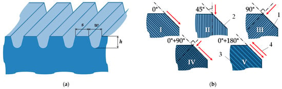
Figure 2.
Microtextures formed on the rake face of the PCD tool: (a) a profile of the microtextures, where w is the groove width, s is the step between grooves, and h is the depth of a groove; (b) directions of microgrooves, where (1) is a rake face of the PCD insert, (2) is a chamfer, (3) is a single groove, (4) is a direction of the formed groove (red arrows), I is microtextures at 0° to the chamfer edge, II is microtextures at 45° to the chamfer edge, III is microtextures at 90° to the chamfer edge, IV is crosshatching microtextures at 0° and 90° to the chamfer edge, and V is microtextures with a double groove at 0° to the chamfer edge.
S. Maeng et al. [42] have researched nanogrooves as textures on the rake face of PCD tools without lubrication to reduce the coefficient of friction in ultra-precision machining of tungsten carbide (WC, hard alloy). The PCD tool had an edge radius of 350 nm when the waviness of the cutting edge was 203 nm. The authors expected that the low value of the coefficient of friction would reduce the thermal load (heat) between the tool and workpiece and thereby extend the operational life of the cutting tool. The nanogrooves were produced by a focused-ion-beam method parallel and orthogonal to the cutting edge. The processing factors are presented in Table 2. The perpendicular textures comprised eight grooves with the following parameters: width (w) of 0.8 μm, depth (h) of 1 μm, pitch (spacing, s) of 1 μm, and length (l) from 35 to 120 µm (Figure 3a). The pattern was at a distance (m) of 2 µm from the cutting edge with the width of the textures (wt) of 6.4 µm. The parallel grooves were engraved at the same distance from the cutting edge (m), length (l), and width (wt), and with the same groove parameters (w, h, s) to provide a similar area of textures on the rake face (Figure 3b). The texture length in the cutting direction was equal to the length of the contact pad between the tool and the workpiece. It was observed that the coefficient of friction of the cutting tool with the perpendicular-textured tool was decreased by 10%, and for the parallel-textured one, by 7%. The surface roughness parameter Ra varied from 130 to 220 nm for perpendicular nanogrooves and from 140 to 195 nm for parallel nanogrooves, with Ra in the range of 145–205 nm. Thus, the better result in the context of the final product surface quality has demonstrated that with the parallel nanogrooves, Ra was improved by 3.44–4.87%. This effect can be called insignificant on the considered scale, but it shows that the parallel pattern of the grooves is preferable over the perpendicular one.
Table 2.
The factors of etching of nanogrooves by a focused ion beam (ablation).
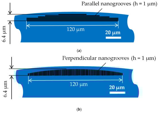
Figure 3.
Nanogrooves on the rake face of the PCD tool produced by focused ion beam (nanogrooves are shown schematically, not to scale): (a) parallel; (b) perpendicular.
P. Ghosh et al. [40] investigated the cutting performance and anti-adhesive properties of micro- and nanotextured PCD cutting inserts in turning Al 6082 aluminum alloy. The PCD cutting inserts were of a diamond composite structure with an average grain size of 10 μm and were infiltrated with a Co binder at ~10.3% vol. The inserts were SPGN090308F in shape with a 0.5 mm diamond layer synthesized on a WC substrate of 1.1 mm. The textures were engraved by fiber laser with the factors presented in Table 3. The depth (h) of the grooves was 260 nm, the width (w) was 7 μm, and the spacing (pitch, s) was 20 μm. Three types of texturing were produced on the rake face: grooves perpendicular and parallel to the chip flow direction at an acute angle and grooves parallel to the main cutting edge (Figure 4). Those cutting inserts with the produced textures were compared with non-textured cutting inserts. The cutting performance was tested under dry conditions. The testing showed that the feed force (in the context of the study, cutting force, Fc) for the cutting tool with perpendicular grooves was 20–40 N, which is more stable than the non-textured inserts of 6–41 N for the cutting tool with parallel grooves. The values of thrust force (Ft) for cutting inserts with grooves parallel and perpendicular to the chip flow direction demonstrated a consistent trend and varied in the range of 60–75 N, whereas the values of Ft for the non-textured cutting insert varied in the range of 73–90 N.
Table 3.
The factors of laser engraving of micro/nanotextures by an infrared nanosecond-pulsed ytterbium fiber laser (ablation).
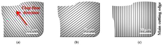
Figure 4.
Graphical presentation of the micro/nanotextures on the rake face of the PCD cutting insert produced by fiber laser: (a) parallel to the chip flow direction (at 135° to the main cutting edge); (b) perpendicular to the chip flow direction (at 45° to the main cutting edge); (c) parallel to the main cutting edge (0°).
The reduction in the coefficient of friction was observed for the cutting inserts with the grooves parallel to the chip flow direction compared with the non-textured cutting inserts: ~0.28 was for the grooves parallel to the chip flow direction, and ~0.34 was for the non-textured cutting inserts. The adhesion of the workpiece material to the rake face of the cutting inserts was also visually reduced. During testing of cutting inserts with perpendicular-to-chip-flow-direction grooves, cutting forces were decreased by 23%, while the surface quality parameter was improved by ~12%. Thus, the geometry of the textures produced on the rake face of the cutting inserts is preferable for a better product performance. The reduction in cutting forces for the cutting insert with grooves parallel to the chip flow direction was ~12%, which is two times less than for the perpendicular ones. Adhesion was decreased by 59% and the coefficient of friction by 14% for microgrooves perpendicular to the chip flow direction. The chip formation mechanism and chip flow are affected by the micro- and nanotextured groove structures and the direction.
2.2. Influence of Texture Profile and Shape
The authors of [36] have investigated the effect of microtexturing of the PCD tool on cutting forces and tool wear, the roughness of the resulting surface of SiCp/Al composites in dry cutting conditions, and the direction of chip flow to produce an anti-adhesion effect. The SiCp/Al composites are widely used in the aerospace, automotive, and medical industries due to their high strength, high wear resistance, and low thermal conductivity. However, in machining, SiCp/Al composites are considered difficult-to-cut materials because of the SiC particles and the ductile behavior of the aluminum matrix at high temperatures developed during cutting due to the presence of SiC particles. In this context, SiC causes increased wear of the cutting tool when aluminum tends to exhibit increased adhesion, which also hinders cutting. The SiCp/Al composites are composed of an aluminum matrix and SiC particles that are pointed in shape and measure 2–12 μm, evenly distributed in the aluminum matrix. The PCD tool had a medium grain of 0.01 mm and a hardness of 8000 HV, which is 3–5 times harder than hard alloy, with the thermal conductivity of 700 W/(m·K), and is often used in machining SiC particle-reinforced aluminum matrix composites with low volume fractions of SiC particles. An infrared nanosecond laser was used to produce textures on the PCD tool due to its greater thermal effect compared to other types of laser sources (femtosecond, picosecond, and ultraviolet nanosecond lasers). The laser texturing factors are presented in Table 4. The PCD tool (cutting insert) textures were as follows: a distance from the cutting edge (m) of 25–45 µm, a microgroove width (w) of 16 μm, a microgroove length (l) of 1000 µm, a microgroove spacing (s) of 40–80 µm, and a depth (h) of 70 µm. The groove in the plan was a kerf of a typical torch-shaped form, with rounded edges, and had outer and inner diameters of 16 and 6 μm, respectively. The microgrooves were performed at an angle of 0° to the cutting edge of the rhombic cutting insert, as close as possible to a round tip in plan. The cutting depth (ap) was 20 μm, and the cutting speed (vc) was 200 mm/s. The reduction in cutting forces was detected at a distance between the cutting edge and textures (m) equal to 35 µm. The spacing between the textures did not play any significant role in the cutting force components. However, the lowest data were obtained for a combination with a distance from the cutting edge (m) of 35 µm and a step (s) of 40 or 60 µm. The decrease in the main and normal cutting forces was 4–20% (the main cutting force has been reduced from 23.5 N to ~20 N and that is 17%; the normal cutting force has been reduced from 12.5 N to 12 N and 10 N and that is 4% and 20% for a step of 40 and 60 µm, respectively). The results of 3D modeling showed that grooves with rounded edges are preferable to grooves with chamfers and grooves with a rectangular profile, since they do not create additional cutting stress in the chip flow zone (Figure 5). Microcutting tests on the workpiece of 10 × 10 × 0.8 mm have shown that the roughness parameter Ra of the workpiece surface was reduced from 0.32 µm for the original tool to 0.25 µm for the tool with a distance from the cutting edge (m) of 35 µm and a step (s) of 40 µm. The roughness parameter Ra for the tools with a distance from the cutting edge (m) of 35 µm and a step (s) of 60 and 80 µm, and with a distance from the cutting edge (m) of 40 µm and a step (s) of 40 µm achieved ~0.27 µm. The key importance in this context was held by the particles of the composite, which should be more than the width of the kerf from one point of view and less than the limit value from another point of view, where the microtexturing has shown no effect.
Table 4.
The factors of laser engraving of microtextures by an infrared nanosecond-pulsed ytterbium fiber laser (ablation).
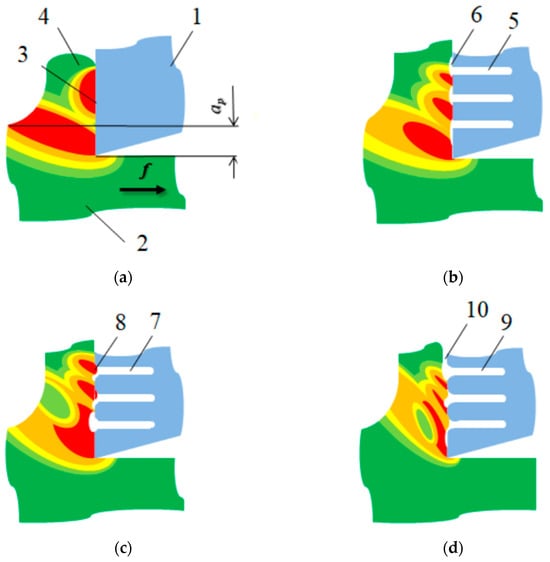
Figure 5.
Illustration of the simulation results of the temperature fields and features of chip flow in cutting homogenous material with a cutting tool, where the gradation of colors indicates the temperature fields from 20 °C to 550–580 °C: (a) without microtextures; (b) with rectangle profile in plan microtextures; (c) with microtextures with a chamfer; (d) with microtextures with rounded edges, where f is a feed direction (indicated by an arrow), ap is a cutting depth (indicated by dimension lines), (1) is a cutting tool, (2) is the homogenous material of the workpiece, (3) is an area of the contact between the cutting tool and workpiece (contact pad), (4) is the formation of the chip, (5) is a rectangle in plan microtexture, (6) is the formation of the gap between the cutting tool and workpiece, (7) is the microtexture with a chamfer, (8) is extrusion of the material into the kerf, (9) is a microtexture with round edges, (10) is the absence of contact between the cutting tool and workpiece (stable gap).
The authors of [38] have studied the flank wear on the microtextured PCD tool during milling of a SiCp/Al composite. The effect of applying pit, groove, and hybrid micro-textures produced on the rake face of a hard alloy inlaid with a PCD tool with a diameter of 10 mm was discussed (Figure 6). The better results were demonstrated by the hybrid microtextured tool. Special attention was paid to the tool service life, cutting forces during cutting, and the self-lubrication mechanism. The microtexture is fabricated using the factors presented in Table 5. It should be noted that because the effect of a femtosecond laser is very short in time, the phase transformation of the tool material is often referred to as direct ablation (a transition from a solid to a vapor state). It significantly reduces the negative effects associated with continuous exposure to a laser beam, such as droplet formation, splashing, remelting of the melt pool, mixing of the upper layer with the underlayered material, and the formation of secondary second-order structures (mainly oxides) [63,64]. Therefore, the tool material exposed to a femtosecond laser is freed from the negative consequences of these effects in advance [65,66].
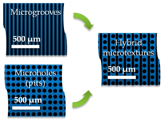
Figure 6.
Three types of developed and produced microtextures on the rake face of the cutting tool made of hard alloy and inlaid with PCD for testing in milling SiCp/Al composite, where the green arrows show that the hybrid texture consisted of a combination of the developed microgrooves and microholes.
Table 5.
The factors of laser engraving of microtextures by a femtosecond laser (ablation).
The parameters of the microtextures were as follows:
- The width (w) and spacing (s) were 15 μm and 50 μm for the grooves (three groove widths were researched—10, 15, and 25 µm, where 15 µm has shown a better tool performance);
- The diameter (d) and spacing (s) were 50 μm and 80 μm for the pit (t two horizontal spacings (s1 = 80, 100 µm) and two vertical spacings (s2 = 80, 120 µm) were researched, where the spacing s1 = s2 = 80 µm demonstrated a better tool performance);
- The pit diameter (d) and groove width (w) were 50 μm and 15 μm, respectively, when the horizontal and vertical distance between textures (s1 and s2, respectively) was 70 μm for the hybrid microtextures.
Milling factors were as follows: a spindle speed (n) of 1205 min−1, a feed rate (fz) of 0.07 mm/z, a depth of cut (ap) of 0.8 mm, a width of cut (ae) of 2.14 mm, and a feed stroke (x) of 500 mm. The wear criterion was the flank wear of 0.35 mm. The coefficient of friction was 0.225 for non-textured tools and 0.08–0.10 for textured cutting tools, where 0.102 was detected for microgrooves, 0.095 for microholes, and 0.093 for hybrid microtextures. The hybrid microtextures show a 37% reduction in wear volume. The minimal roughness parameter Ra was 1.152 µm, achieved at n = 1600 min−1, fz = 0.23 mm/z, ap = 0.8 mm, and ae = 3.2 mm. The measured components of cutting force were Fx = 17.57 N, Fy = 55.45 N, and Fz = 16.05 N. The flank wear of the cutting tool with hybrid microtextures was 53.8% lower than that for non-textured tools. The operational life of the cutting tool for a tool with hybrid microtextures was 480 s, when the operational life of the non-textured tool did not exceed 225 s. The roughness parameter Ra was not improved: it was 1.4 µm for the non-textured tool and 1.45 µm for the tool with the hybrid microtextures, and that is an acceptable result.
X X. Wang et al. [67] devoted their research to analyzing the influence of microtextures in the shape of microholes (pits) on the performance of the PCD tool in turning a SiCp/Al composite. The microtextures were produced using the factors presented in Table 6. The distance from the main cutting edge (m) was 35 μm, and the spacing (s) was 60 μm. The main cutting force was reduced by ~14% when the tool wear and surface adhesion were also reduced. Testing of the produced PCD tool in turning SiCp/Al composites showed that the cutting force was reduced by 22%, improving chip flow and PCD tool anti-tipping. The micropit array texture with rounded corners enabled smooth chip flow during machining. The textured tool increased chip curvature during orthogonal turning.
Table 6.
The factors of laser engraving of microholes on the rake face of a PCD tool for turning a SiCp/Al composite by an infrared nanosecond-pulsed ytterbium fiber laser (ablation).
3. Influence of Processing Factors on the Efficiency of Microtextures
3.1. Influence of Laser Technology Factors on the Parameters of Microtextures
Y. Su et al. [41] compared the geometrical parameters of microgrooves and microholes (pits) produced on the rake face of the PCD tool (CTB010 grade, grain size—10 µm, Co binder) using a fiber laser (YLP-1-100-20-20-RG) with different processing modes. The laser graving factors are presented in Table 7. During texturing, it was noted that the parameters of the microtextures, such as width, diameter, and depth, were smaller with a higher scanning speed (for microgrooves) and pulse repetition rate and a lower average output power (Figure 7). The parameters of microtextures were significantly affected by the value of the defocusing distance (Δ, the distance from the matrix to the object). The maximum depth (h = 55 µm for the microgrooves and h = 73 µm for the microholes) and smoother edges were achieved when Δ = −0.8 mm. The sidewall topography of the microgrooves was improved by increasing the average output power or decreasing the scanning speed. An optimization of the laser processing factors allows for control of the microtextural parameters. The sizes of the produced microtextures were as follows:
Table 7.
The factors of laser engraving of microgrooves and microholes on the rake face of a PCD tool by an infrared nanosecond-pulsed ytterbium fiber laser (ablation) to investigate the influence of laser factors on the size of microgrooves and microholes.
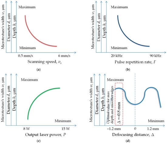
Figure 7.
The influence of the infrared nanosecond-pulsed ytterbium fiber laser factors on the parameters of the microtextures produced on the rake face of the PCD tool, depending on (a) scanning speed; (b) pulse frequency; (c) laser power; (d) defocusing distance, where the section of the graph with the best result (the largest diameter, depth, and width of microtextures) is marked by a red dotted line box, where Δ = −0.8 mm.
- The width (w) of 30 µm for the microgrooves at the power P = 11 W;
- The diameter (d) of 60 µm for the microholes (pits) at the power P = 13 W.
Similar findings were presented in [68]. X. Sun et al. have researched the influence of the nanosecond laser factors, such as laser power, pulse power, and defocusing distance, on the parameters of microholes (diameter, depth, recast layer). The microholes were produced on the rake face of the PCD with the factors presented in Table 8. The laser energy per pulse (E) was 1 mJ for P = 20 W and F = 20 kHz. The resulting diameter of microholes varied in the range of 2–5.3 µm, and the resulting depth varied in the range of 10–26 µm (Figure 8). The minimum recast layer was achieved at the defocusing distance of −2 µm, with a power of 8 W and a pulse frequency of 100 kHz.
Table 8.
The factors of laser engraving of microholes on the rake face of a PCD tool by an infrared nanosecond-pulsed ytterbium fiber laser (ablation) to investigate the influence of pulse frequency and power on the size of microholes.
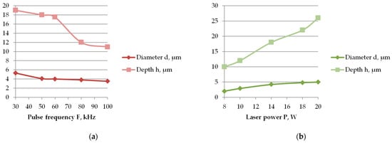
Figure 8.
The dependence of the microhole parameters (diameter and depth) on the infrared nanosecond laser factors in microtexturing of the PCD cutting insert rake face: (a) pulse frequency; (b) power.
3.2. Influence of Microtextural Area on the Tribological Characteristics of a PCD Tool
S. Fang et al. [69] researched different microtextures: microgrooves, microholes, and micronodes (cross-hatching) produced on the PCD tool with Co binder by a Ti-Sapphire femtosecond laser. The laser graving factors are presented in Table 9. The laser spot size was ~17 µm, the scanning speed was 2.5 mm/s, and the spot overlap was 85.5%. The produced microtextures were with the depth (h) of ~3 µm; other parameters were as follows (Figure 9):
Table 9.
The factors of laser engraving of microtextures by an infrared femtosecond-pulsed titanium–sapphire fiber laser (ablation).
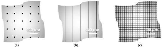
Figure 9.
Graphical presentation of the microtextures on the PCD sample produced by femtosecond laser: (a) microholes; (b) microgrooves; (c) micronodes (cross-hatching).
- Microhole diameter (d) was ~21 µm, and the spacing (s) was 400 µm in both directions;
- Microgroove and micronode width (w) was ~15 µm, and the spacing (s) was 400 µm for the microgrooves and 100 µm for the micronodes.
The tribological tests (after 400–900 cycles using a steel ball of AISI 52100 with the diameter of ø3 mm with a normal load and lubricant with kinematic viscosity of 9.00 mm2/s) have demonstrated the smallest value of the coefficient of friction for the PCD samples with the micronodes (0.08), when the coefficients of friction for microgrooves and microholes were 0.10 and 0.16, respectively (Figure 10). The result is probably related to the correlation between the microtextured and non-textured surfaces. Due to the extra-short (femto) laser ablation pulse duration, no visible damage from the thermal exposure typical of laser processing was detected [70,71,72].
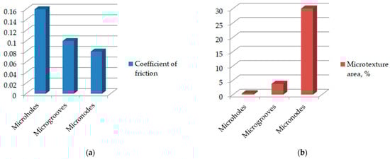
Figure 10.
The correlation between the coefficient of friction of the PCD samples with various types of microtextures and the microtexture area (%): (a) coefficient of friction; (b) microtexture area (%), which was calculated as follows: .
Table 10 summarizes the processing factors for producing microtextures with various types of lasers and the parameters of the microgrooves, microholes, and micronodes produced on the PCD tool. The provided data and findings can be recommended for industrial applications.
Table 10.
The correlation between the laser processing factors and microtextural parameters.
4. Specific Features of Microtexturing of PCD Tool and Performance
4.1. Effect of Microtextures and Cryogen Lubrication on Flank Wear
Y. Su et al. [35] investigated the anti-friction and anti-adhesion properties of microtextured PCD tools in high-speed turning of Ti6Al4V alloy. The microgrooves were produced using a fiber laser with the factors listed in Table 11. The time for the production of the microgroove array was ~1500 s. The microgrooves were placed parallel to the cutting edge (type I). The microgroove parameters were as follows: the distance from the cutting edge to the microgrooves (m) of 300 µm, the length (l) of 1500 µm, the width (w) of 60 µm, the depth (h) of 53 µm (the measurements by a profilometer showed ~63.3 µm), and the spacing (s) of 85 µm. Four types of experimental options were tested in turning titanium alloy: a non-textured PCD tool in dry cutting conditions and with cryogen minimum quantity lubrication (CMQL), a microgrooved PCD tool in dry cutting conditions and with CMQL. The lubrication conditions were as follows: air pressure of 0.4 MPa, air flow rate of 120 L/min, cooling-air temperature of −15 °C, and oil flow rate of 10 mL/h. The lubricating oil was Vascomill MMS FA1. The turning conditions were the cutting speed (vc) of 20−180 m/min. The experiments demonstrated that the coefficient of friction reduces as the cutting speed increases. A microgrooved tool without lubrication reduces the coefficient of friction from 0.75 to 0.8 (for other experimental options) to 0.65 (a 13.33–18.75% reduction) at a cutting speed of 20 m/min. For other cutting speed values, microtextures and lubrication options did not show any significant positive effect. The reduced coefficient of friction (μ) was observed in the absence of lubrication for both non-textured and microgrooved PCD tools at the increased cutting speed (~4% at 130 m/min and ~12% at 180 m/min). The flank wear chamfer at a feed rate (f) of 0.19 mm/r, a width of cut (ae) of 2 mm, and a cutting speed (vc) of ~176 m/min was as follows (Figure 11a):
Table 11.
The factors of laser engraving of microgrooves by an infrared nanosecond-pulsed ytterbium fiber laser (ablation).
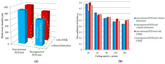
Figure 11.
The flank wear chamfer of non-textured and microgrooved PCD tool options without lubrication and with CMQL at a feed rate (f) of 0.19 mm/r, a width of cut (ae) of 2 mm, and a cutting speed (vc) of ~176 m/min, where the most significant effect is marked by a green dotted line (a); the coefficient of friction μ for different experimental options at the cutting speed (vc) from 20 to 180 m/min (b).
- 547 µm for the non-textured PCD tool without lubrication;
- 582 µm for the non-textured PCD tool with CMQL;
- 418 µm for the microgrooved PCD tool without lubrication;
- 491 µm for the microgrooved PCD tool with CMQL.
As can be seen, the cryogenic lubrication did not have a positive effect on the flank wear chamfer value, when the use of the microgrooved tool allowed for reducing flank wear by 23.6%. The adhesion area on the rake face of the PCD tool in high-speed machining was also reduced by microtexturing (the maximum width of chip adhesion was reduced by 23.6% for the microgrooved tool compared to the non-textured one). The results showed that titanium carbide (TiC) is formed on the rake face of PCD tools as a bonding layer, thereby providing anti-friction conditions at the contact pad between the tool and workpiece. These results show that microtexturing in the form of microgrooves allows for trapping debris, and the TiC bonding layer improves the PCD tool performance. The coefficient of friction for the microgrooved PCD tool without using cutting liquid was 2.67–18% lower than that for the non-textured PCD tool with cryogenic minimum-quantity lubrication [73,74,75,76], when other experimental options have taken the place between those two ones. Without lubrication, the coefficient μ was reduced from 0.77 to 0.65 (15.6%), when comparing the non-textured tool with the microgrooved tool at vc = 20 m/min, and from 0.44 to 0.425 (3.4%) for those tools at vs = 180 m/min (Figure 11b).
C.M. Rao et al. [33] proposed using a microtexture in the form of microholes with tunnels produced by electrical discharge machining with copper wires 0.4 mm and 0.6 mm in diameter. Deionized water was used as a working fluid. The flank wear of PCD cutting inserts in turning Ti6Al4V with MQL was reduced by 62% and 40%. Cutting insert machining produced favorable chip forms with less residual at all the cutting velocities. Chip breakability was achieved through texturing.
4.2. Effect of Lyophobic Wettability of Microtextures on the Tool Performance
G. Sakthivel et al. [37] have researched the anti-friction and self-lubrication effect of the combined approach—cutting tool surface texturing and lyophobic wettability. The surface texturing was performed in the shape of cross-chevron textures using ND:YAG laser graving with the following parameters: the length (horizontal distance, wt) of 1.5 mm, the texture width (vertical distance, l) of 1.5 mm, the width of the grooves (w) was about 80 µm, the texture included an angle of 40°, and the depth (h) was 200 µm. Amino-propyl triethoxy-silane + toluene solution was used to provide lyophobic wettability by dip- and drop-based coating methods (Figure 12). For the dip-coating method, the textured insert was cleaned and processed using sulfuric acid (H2SO4) to activate the carbon content of the insert surface and then dipped in a solution of aminopropyl triethoxysilane (C9H23NO3Si) mixed with toluene (aromatic hydrocarbon) for 24 h. Afterwards, the dipped insert was placed in the furnace for three hours at 120 °C. For the drop-coating method, the textures of the PCD insert rake face were filled one drop by one using a syringe charged with the same solution. The prepared insert was then kept in the furnace at 120 °C for three hours. The hydroxyl (–OH) and carboxyl (–COOH) functional groups on the surface of the PCD insert were activated by the chemical activator (H2SO4) to improve the surface functionality. Those activated groups of chemicals were used to link the amine-terminated precursor, thereby forming a silica (Si-O-Si) framework across the lyophobic layer through hydrolysis and polymerization. The framework has been formed on the surface of the PCD insert by hydrolysis followed by polycondensation at 120 °C.
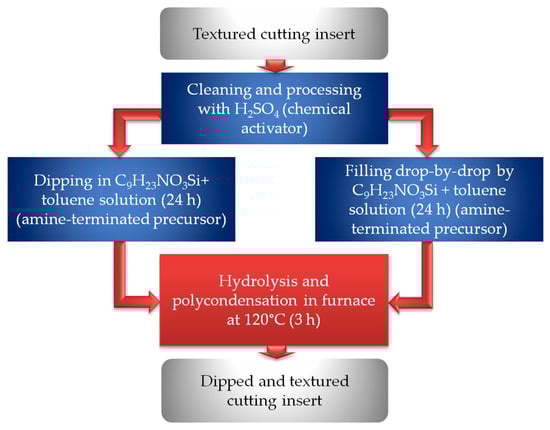
Figure 12.
Schematic of the dip- and drop-coating methods for providing lyophobic wettability to the PCD cutting insert.
After the functionalization of the cutting insert surface and filled textures, the samples were tested under dry conditions, where the cutting speed (vc) varied from 180 to 220 m/min, the depth of cut (ap) was 0.5 mm, and the feed rate (f) was 0.3 mm/rev. Turning experiments were conducted on an Al 6061 T6 aluminum alloy workpiece. The cross-chevron textured insert reduced cutting forces compared to the non-textured insert due to the reduced contact pad between the rake face of the insert and the chip and increased heat dissipation by the textures. The inserts with the lyophobic wettability have demonstrated a better performance than the non-textured insert due to the lubricity and anti-frictional behavior after treatment with amino-propyl triethoxy-silane and toluene solutions. The minimum values of main cutting and thrust forces were observed for the dip-based lyophobic wettability insert: the main cutting force (Fc) was 26–32 N, and the thrust (feed) force (Ft) was 14–17 N. A smaller value of Fc and a larger value of Ff were observed for a larger cutting force. Those values for the other three experimental options were as follows: the insets without texturing—Fc = 65–91 N, Ft = 35–45 N; the inserts with drop-based lyophobic wettability—Fc = 51–63 N, Ft = 28–34 N; and the inserts with cross-chevron textures—Fc = 36–52 N, Ft = 25–31 N. Thus, the reduction was 60–65% for Fc and 60–62% for Ft, when comparing dip-based lyophobic wettability inserts with cross-chevron textures and non-textured inserts.
X. Hao et al. [39] proposed a texture on the rake face of a PCD tool (cobalt binder, grit size 10 µm) with composite lyophilic/lyophobic wettabilities and compared them with a non-textured tool and a tool with microgrooves. Lyophobic micro/nanostructures and lyophilic grooves were produced using a pulsed fiber laser with the factors shown in Table 12. The groove spacing (s) was 30 μm. The 0.8% fluoroalkyl silane solution (the solute of F91 fluorides and solvent of F8063 solution) was chosen for fluorination. The PCD tools with micro/nanotextures were immersed in a 0.8% fluoroalkyl silane solution for 24 h to reduce their wettability. The fluorinated PCD tools were cured in an oven at 140 °C for 120 min. The micro/nanotextures were at the depth of 20 µm with the height of the peaks at 10 µm and orthogonal microgrooves of 10 µm depth from the textures and 20 µm depth from the rake face, and they demonstrated lyophobic wettability after fluorination: the emulsion contact angle of the non-textured tools was increased from 50.74° to 92.40°, and it was increased from 40.39° to 109.20° for the produced textures with lyophobicity (Figure 13a,b). Then, microgrooves perpendicular to the direction of the micro/nanotextures were produced by laser ablation of lyophobic materials, using the factors listed in Table 13 (Figure 13c). The parameters of microgrooved tools were as follows (Figure 13d): the depth (h) of ~10 µm, the width (w) of ~60 µm, and the distance between grooves and the main cutting edge (m) of ~120 μm. The tools were tested under conditions of turning Ti6Al4V alloy at a cutting speed (vc) of 90 m/min, a feed rate (fz) of 0.16 mm/r, a depth of cut (ap) of 0.2 mm, a cutting length (L) of 180 m, and an MQL environment. The rake angle, clearance angle, and cutting edge angle were 0°, 11°, and 45°, respectively. The micro/nanotextured PCD tools with lyophilic/lyophobic wettabilities have reduced the cutting force components (reduction in cutting force Fz by 2.5–3.0 N (3.65%) when comparing microgrooved tool and by 5 N (5.95%) when comparing non-textured tool at vc = 60 m/min) and the coefficient of friction (decreased by 11.5% and 10.9% compared to the non-textured tool and the tool with microgrooves) and have improved the wear resistance compared to other options. That was due to control of the flow of cutting liquid on the contact pad between the tool and the workpiece. After 180 m of cutting distance, the flank wear was 197 µm, 188 µm, and 153 µm for non-textured, microgrooved, and micro/nanotextured tools, respectively, resulting in a 22.3% reduction in flank wear.
Table 12.
The factors of laser engraving of lyophobic micro/nanostructures and lyophilic grooves (Step 1) by an infrared nanosecond-pulsed ytterbium fiber laser (ablation).
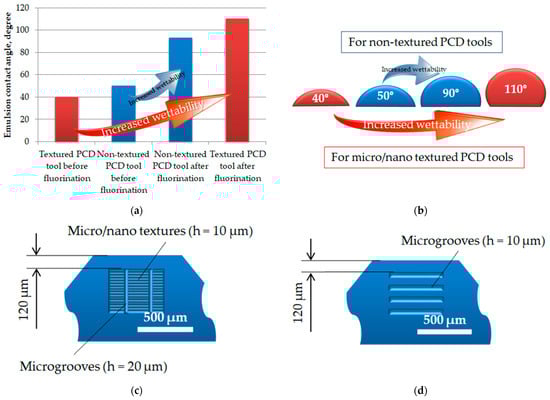
Figure 13.
The influence of the fluorination on the wettability of the micro/nanotextured and non-textured PCD tools: (a) emulsion contact angle histogram for different PCD tool options; (b) the approximate shape of the cutting liquid depending on emulsion contact angle for different PCD tool options; (c) micro/nanotextures on the rake face of the PCD tool; (d) microgrooves on the rake face of the PCD tool.
Table 13.
The factors of laser engraving of lyophobic microgrooves perpendicular to the direction of micro/nanotextures (Step 3) by an infrared nanosecond-pulsed ytterbium fiber laser (ablation).
The summarized data on the influence of lyophobic wettability of microtextures, including fluorination as a step in PCD tool rake face treatment and dip- and drop-based coating techniques, on tool performance are presented in Table 14. Both techniques were used to modify the rake face of the PCD tool (cutting insert) for the turning process.
Table 14.
Effect of lyophobic wettability of microtextures, including fluorination as a step in PCD tool rake face treatment and dip- and drop-based coating techniques, on PCD tool performance in cutting hard-to-cut materials.
5. Summary of the Effect of Microtexturing on the PCD Tool Performance
Table 15 shows a survey of the ability to create texture on the PCD cutting tools. As shown, the most significant effects were achieved using different types of processing technologies for the production of micro- and nanotextures. Meanwhile,
Table 15.
Effect of microtextures on PCD tool performance in cutting hard-to-cut materials.
- The effect of microgrooves perpendicular to the chip flow direction, microholes, and hybrid textures may achieve ~60% and mainly depend on the microtexture area to the area of the contact pad on the rake face rather than on the shape of textures;
- The microgroove orientation is preferably perpendicular to the chip flow direction;
- The effect of microtextures achieves ~20% when the effect of nanotextures does not exceed 5% for the improvement in surface quality parameters of the final product;
- The distance from the main cutting edge (tip) of the PCD tool to the texture should be in the range of 30–300 µm to achieve an effect of up to 20% and more for the flank wear and adhesion reduction, prolongation of the operational life of the tool, and improvement of the surface quality parameters for the final product.
The cost of microtexturing depends on the method, equipment costs, and other factors. Technology scalability is important, as microtexturing systems can be upgraded with additional modules or integrated into expanded production lines as the business grows. The main factors that influence the cost of microtexturing of the PCD tool are additional equipment; fuel and energy for manufacturing; labor wages for production personnel involved in manufacturing that require additional personnel; and overhead costs for production maintenance and management due to the introduction of additional technology steps. The features that are important for the scalability of the microtexturing are as follows:
- Equipment flexibility—machines with programmable controls, interchangeable tools, or digital pattern libraries allow for quick reconfiguration of the equipment for a certain task.
- Ability to integrate into expanded production lines—systems that can be upgraded with additional modules help avoid costly equipment replacements in the future.
- Consideration of cutting tool material characteristics to analyze the influence of additional external influences on the possible initiation of the material degradation.
As was shown in the review, the microtexturing of the PCD tool can be provided by a wide range of technologies:
- Pulsed laser of infrared range of radiation (nano- or femtosecond)—creating regular micro- and nanotextures on the material surface using laser ablation. Typical texture sizes range from a few micrometers to hundreds of micrometers.
- Fused ion beam ablation—forming nanostructures using accelerated ions of gallium. Typical texture sizes are of a few micrometers.
- Electrical discharge machining—forming microstructures on the rake face using copper wire electrodes. Typical texture sizes are of the hundreds of micrometers.
Mechanical methods, such as grinding, micromilling, microindentation, and ultrasonic machining, are not typically used for texturing PCD tools due to their specific physical and mechanical properties (e.g., high hardness of 8000–10,000 HV).
It should be noted that the most cost-effective or economically beneficial solutions are related to the technologies that do not require specific equipment and use the equipment that already exists on the manufacturing site—laser graving and electrical discharge machines, when femtosecond lasers and a fused ion beam setups are less common, require more stringent operating conditions, and are only possible with scalable production.
Concerning the technique related to the dip-based lyophobic wettability coatings that as was shown play a significant role in improving the effect of the textures (the reduction was by 60–65% for cutting force component Fc and 60–62% for the Ft cutting force component, when comparing the dip-based lyophobic wettability inserts with cross-chevron textures and non-textured inserts), it requires additional costs on the personnel, material, equipment (oven, a special room with an appropriate ventilation system, workplaces), overhead costs (additional costs of production maintenance and management), enlarging the production cycle (by ~1.5 work days), and quality control, and it is possible as well with scalable production.
Regarding the micro/nanotextured PCD tools with lyophilic/lyophobic wettabilities, they reduce the cutting force component Fz by 2.5–3.0 N (3.65%) compared to the microgrooved tool and by 5 N (5.95%) compared to the non-textured tool at the cutting force vc = 60 m/min. That is considered a good result, but the technique requires an additional 24 h immersion in the 0.8% fluoroalkyl silane solution (enlarging the production cycle by ~1.5 work days), as well as the additional costs on the personnel, material, equipment, overhead costs, and quality control, and these are too high as additional costs for the considered effect of the technique.
6. Conclusions
The provided systematization of the most recent advances in micro- and nanotexturing of PCD tools for machining aluminum and titanium alloys, SiCp/Al composites, and a hard alloy allows us to summarize the techniques and technologies used and their effect on the prolongation of the service life of the tool, flank wear, and roughness parameters of the final product. The following conclusions are drawn:
- The effect of textures on the rake face of the PCD tool mainly depends on the textured area to provide a smaller contact pad between the tool and workpiece;
- There are no specific differences between the microgrooves perpendicular to the chip flow direction, microholes, micronodes, cross-chevron, and hybrid textures, and an ~60% effect may be achieved;
- The microgroove orientation is preferably perpendicular to the chip flow direction (at 45° to the main cutting edge) to provide a better tool performance (the reduction in cutting forces for the cutting insert with perpendicular grooves to the chip flow direction was ~24%; the adhesion was decreased by 59%, and the coefficient of friction by 14%);
- The effect of microtextures is at least five times more significant than the effect of nanotextures on the surface quality parameters of the final product;
- The distance from the main cutting edge (tip) of the PCD tool to the texture plays one of the key roles and should be in the range of 30–300 µm to achieve the effect of up to 20% and more for the flank wear and adhesion reduction, prolongation of the operational life of the tool, and improvement of the surface quality parameters for the final product;
- The dip-based lyophobic wettability coatings play a significant role in improving the effect of the textures, and thus the effect created by the use of the textured PCD tool on the machined surface;
- The depth of the textures should be around 100–300 µm to provide a remarkable effect in reducing cutting forces by ~60%, when the effect of a smaller texture depth (10–70 µm) is less significant (around 20%);
- The smoother edges of the textures play a positive role in the chip flow convergence, while the sharp edges and chamfers hamper it; thus, the defocusing of the laser spot by −0.5 to −1.0 µm in laser engraving and ablation is strongly recommended.
Author Contributions
Conceptualization, S.N.G. and M.A.V.; methodology, S.N.G. and A.S.M.; software, K.H. and A.A.O.; validation, K.H. and A.A.O.; formal analysis, A.S.M.; investigation, A.A.O.; resources, A.S.M.; data curation, A.S.M.; writing—original draft preparation, K.H. and A.A.O.; writing—review and editing, A.A.O. and M.A.V.; visualization, K.H. and A.A.O.; supervision, S.N.G.; project administration, M.A.V.; funding acquisition, M.A.V. All authors have read and agreed to the published version of the manuscript.
Funding
The research was financially supported by the Ministry of Science and Higher Education of the Russian Federation (project no. FSFS-2026-0003).
Data Availability Statement
The original contributions presented in this study are included in the article, and further inquiries can be directed to the corresponding authors.
Conflicts of Interest
The authors declare no conflicts of interest.
References
- Benedicto, E.; Rubio, E.M.; Carou, D.; Santacruz, C. The Role of Surfactant Structure on the Development of a Sustainable and Effective Cutting Fluid for Machining Titanium Alloys. Metals 2020, 10, 1388. [Google Scholar] [CrossRef]
- Varga, G.; Markopoulos, A.P. Tribological Aspects of Slide Friction Diamond Burnishing Process. Materials 2025, 18, 4500. [Google Scholar] [CrossRef]
- Bruzzone, A.A.G.; Costa, H.L.; Lonardo, P.M.; Lucca, D.A. Advances in engineered surfaces for functional performance. CIRP Ann. 2008, 57, 750–769. [Google Scholar] [CrossRef]
- Grigoriev, S.N.; Volosova, M.A.; Fedorov, S.V.; Migranov, M.S.; Mosyanov, M.; Gusev, A.; Okunkova, A.A. The Effectiveness of Diamond-like Carbon a-C:H:Si Coatings in Increasing the Cutting Capability of Radius End Mills When Machining Heat-Resistant Nickel Alloys. Coatings 2022, 12, 206. [Google Scholar] [CrossRef]
- Metel, A.S.; Grigoriev, S.N.; Tarasova, T.V.; Filatova, A.A.; Sundukov, S.K.; Volosova, M.A.; Okunkova, A.A.; Melnik, Y.A.; Podrabinnik, P.A. Influence of Postprocessing on Wear Resistance of Aerospace Steel Parts Produced by Laser Powder Bed Fusion. Technologies 2020, 8, 73. [Google Scholar] [CrossRef]
- Zhu, W.-L.; Xing, Y.; Ehmann, K.F.; Ju, B.-F. Ultrasonic elliptical vibration texturing of the rake face of carbide cutting tools for adhesion reduction. Int. J. Adv. Manuf. Technol. 2016, 85, 2669–2679. [Google Scholar] [CrossRef]
- Cui, Y.; Wang, D.; Zheng, M.; Li, Q.; Mu, H.; Liu, C.; Xia, Y.; Jiang, H.; Wang, F.; Hu, Q. Study on Cutting Performance and Wear Resistance of Biomimetic Micro-Textured Composite Cutting Tools. Metals 2025, 15, 697. [Google Scholar] [CrossRef]
- Salem, A.; Hegab, H.; Kishawy, H.A. Experimental Investigation of the Derivative Cutting When Machining AISI 1045 with Micro-Textured Cutting Tools. Metals 2023, 13, 1587. [Google Scholar] [CrossRef]
- Volosova, M.A.; Okunkova, A.A.; Hamdy, K.; Malakhinsky, A.P.; Gkhashim, K.I. Simulation of Mechanical and Thermal Loads and Microtexturing of Ceramic Cutting Inserts in Turning a Nickel-Based Alloy. Metals 2023, 13, 1241. [Google Scholar] [CrossRef]
- Pratap, A.; Patra, K. Combined effects of tool surface texturing, cutting parameters and minimum quantity lubrication (MQL) pressure on micro-grinding of BK7 glass. J. Manuf. Process. 2020, 54, 374–392. [Google Scholar] [CrossRef]
- Wang, M.; Huan, H.; Zhao, B.; Ding, W.; Luo, T.; Yao, R.; Wu, J. Evaluation of cutting performance of microtextured PCD tools on particle-reinforced titanium matrix composites. Int. J. Refract. Met. Hard Mater. 2025, 128, 107060. [Google Scholar] [CrossRef]
- Zhang, H.; Tong, X.; Wang, B. Research on the Friction Prediction Method of Micro-Textured Cemented Carbide–Titanium Alloy Based on the Noise Signal. Coatings 2025, 15, 843. [Google Scholar] [CrossRef]
- Wang, X.; Yang, M.; Gao, T.; Dong, L.; Dambatta, Y.S.; Liu, X.; Yang, Y.; An, Q.; Zhang, Y.; Li, C. Lubricant Transport Mechanism and Dynamics Model for Nepenthes-shaped Biomimetic Microtexture. Chin. J. Mech. Eng. Engl. Ed. 2025, 38, 36. [Google Scholar] [CrossRef]
- Patel, K.V.; Jarosz, K.; Özel, T. Physics-Based Simulations of Chip Flow over Micro-Textured Cutting Tool in Orthogonal Cutting of Alloy Steel. J. Manuf. Mater. Process. 2021, 5, 65. [Google Scholar] [CrossRef]
- Tong, X.; Liu, X.; Yu, S. Anti-Friction and Anti-Wear Mechanisms of Micro Textures and Optimal Area Proportion in the End Milling of Ti6Al4V Alloy. J. Manuf. Mater. Process. 2019, 3, 91. [Google Scholar] [CrossRef]
- Liu, Y.; Wang, G.; Jia, F.; Jiang, X.; Jiang, N.; Wang, C.; Lin, Z. Improvements in Wettability and Tribological Behavior of Zirconia Artificial Teeth Using Surface Micro-Textures. Materials 2025, 18, 3117. [Google Scholar] [CrossRef]
- Sheng, Z.; Zhu, H.; He, Y.; Shao, B.; Sheng, Z.; Wang, S. Tribological Effects of Surface Biomimetic Micro–Nano Textures on Metal Cutting Tools: A Review. Biomimetics 2025, 10, 283. [Google Scholar] [CrossRef]
- Shang, P.; Liu, B.; Guo, C.; Cui, P.; Hou, Z.; Jin, F.; Zhang, J.; Guo, S.; Huang, Y.; Zhang, W. Study on Effect of Surface Micro-Texture of Cemented Carbide on Tribological Properties of Bovine Cortical Bone. Micromachines 2024, 15, 994. [Google Scholar] [CrossRef]
- Tang, Z.; Ge, Z.; Li, J. Design and experimental study of biomimetic microtextured hard alloy cutting tools based on sparse matrix and hydrodynamic lubrication theory. J. Mater. Sci. 2024, 59, 14621–14638. [Google Scholar] [CrossRef]
- Grigoriev, S.N.; Okunkova, A.A.; Volosova, M.A.; Hamdy, K.; Metel, A.S. Electrical Discharge Machining of Al2O3 Using Copper Tape and TiO2 Powder-Mixed Water Medium. Technologies 2022, 10, 116. [Google Scholar] [CrossRef]
- Hernández-Pérez, M.; Hernández-Castellano, P.M.; Salguero-Gómez, J.; Sánchez-Morales, C.J. Improved Design of Electroforming Equipment for the Manufacture of Sinker Electrical Discharge Machining Electrodes with Microtextured Surfaces. Materials 2025, 18, 1972. [Google Scholar] [CrossRef]
- Volosova, M.A.; Okunkova, A.A.; Kropotkina, E.Y.; Mustafaev, E.S.; Gkhashim, K.I. Wear Resistance of Ceramic Cutting Inserts Using Nitride Coatings and Microtexturing by Electrical Discharge Machining. Eng 2025, 6, 11. [Google Scholar] [CrossRef]
- Rosas, J.; Lopes, H.; Guimarães, B.; Piloto, P.A.G.; Miranda, G.; Silva, F.S.; Paiva, O.C. Influence of Micro-Textures on Cutting Insert Heat Dissipation. Appl. Sci. 2022, 12, 6583. [Google Scholar] [CrossRef]
- Tong, X.; Wang, X.; Li, X.; Wang, B. Study on the Optimization of Textured Coating Tool Parameters Under Thermal Assisted Process Conditions. Coatings 2025, 15, 876. [Google Scholar] [CrossRef]
- Xu, L.; Yang, D.; Zhang, Z.; Liu, M. Study of the Cutting Performance of Ti-6Al-4 V Alloys with Tools Fabricated with Different Microgroove Parameters. Materials 2025, 18, 4312. [Google Scholar] [CrossRef]
- Picard, Y.N.; Adams, D.P.; Vasile, M.J.; Ritchey, M.B. Focused ion beam-shaped microtools for ultra-precision machining of cylindrical components. Precis. Eng. 2003, 27, 59–69. [Google Scholar] [CrossRef]
- Stebulyanin, M.; Ostrikov, E.; Migranov, M.; Fedorov, S. Improving the Efficiency of Metalworking by the Cutting Tool Rake Surface Texturing and Using the Wear Predictive Evaluation Method on the Case of Turning an Iron–Nickel Alloy. Coatings 2022, 12, 1906. [Google Scholar] [CrossRef]
- Grigoriev, S.N.; Volosova, M.A.; Okunkova, A.A.; Fedorov, S.V.; Hamdy, K.; Podrabinnik, P.A. Elemental and Thermochemical Analyses of Materials after Electrical Discharge Machining in Water: Focus on Ni and Zn. Materials 2021, 14, 3189. [Google Scholar] [CrossRef]
- Grigoriev, S.N.; Volosova, M.A.; Okunkova, A.A.; Fedorov, S.V.; Hamdy, K.; Podrabinnik, P.A. Sub-Microstructure of Surface and Subsurface Layers after Electrical Discharge Machining Structural Materials in Water. Metals 2021, 11, 1040. [Google Scholar] [CrossRef]
- Melnik, Y.A.; Kozochkin, M.P.; Porvatov, A.N.; Okunkova, A.A. On Adaptive Control for Electrical Discharge Machining Using Vibroacoustic Emission. Technologies 2018, 6, 96. [Google Scholar] [CrossRef]
- Grigoriev, S.N.; Volosova, M.A.; Okunkova, A.A.; Fedorov, S.V.; Hamdy, K.; Podrabinnik, P.A.; Pivkin, P.M.; Kozochkin, M.P.; Porvatov, A.N. Wire Tool Electrode Behavior and Wear under Discharge Pulses. Technologies 2020, 8, 49. [Google Scholar] [CrossRef]
- Thirumalai Kumaran, S.; Ko, T.J.; Uthayakumar, M.; Adam Khan, M.; Niemczewska-Wójcik, M. Surface texturing by dimple formation in TiAlSiZr alloy using μ-EDM. J. Aust. Ceram. Soc. 2017, 53, 821–828. [Google Scholar] [CrossRef]
- Rao, C.M.; Rao, S.S.; Herbert, M.A. Development of novel cutting tool with a micro-hole pattern on PCD insert in machining of titanium alloy. J. Manuf. Process. 2018, 36, 93–103. [Google Scholar] [CrossRef]
- Fernández-Lucio, P.; Villarón-Osorno, I.; Pereira Neto, O.; Ukar, E.; López de Lacalle, L.N.; Gil del Val, A. Effects of laser-textured on rake face in turning PCD tools for Ti6Al4V. J. Mater. Res. Technol. 2021, 15, 177–188. [Google Scholar] [CrossRef]
- Su, Y.; Li, L.; Wang, G.; Zhong, X. Cutting mechanism and performance of high-speed machining of a titanium alloy using a super-hard textured tool. J. Manuf. Process. 2018, 34, 706–712. [Google Scholar] [CrossRef]
- Wang, X.; Popov, V.L.; Yu, Z.; Li, Y.; Xu, J.; Li, Q.; Yu, H. Evaluation of the cutting performance of micro-groove-textured PCD tool on SiCp/Al composites. Ceram. Int. 2021, 48, 32389–32398. [Google Scholar] [CrossRef]
- Sakthivel, G.; Sathiya Narayanan, N.; Vedha Hari, B.N.; Sriraman, N.; AanandhaManikandan, G.; Suraj Nanduru, V.S.P. Performance of surface textured PCD inserts with wettability chemical solutions for machining operation. Mater. Today Proc. 2021, 46, 8283–8287. [Google Scholar] [CrossRef]
- Wu, F.; Zhang, N.; Peng, W.; Sun, Y.; Li, X.; Wang, Z. A novel hybrid micro-texture for improving the wear resistance of PCD tools on cutting SiCp/Al composites. J. Manuf. Process. 2023, 101, 930–942. [Google Scholar] [CrossRef]
- Hao, X.; Cui, W.; Li, L.; Li, H.; Khan, A.M.; He, N. Cutting performance of textured polycrystalline diamond tools with composite lyophilic/lyophobic wettabilities. J. Mater. Process. Technol. 2018, 260, 1–8. [Google Scholar] [CrossRef]
- Ghosh, P.; Pacella, M. Effect of laser texturing on the performance of ultra-hard single-point cutting tools. Int. J. Adv. Manuf. Technol. 2020, 106, 2635–2648. [Google Scholar] [CrossRef]
- Su, Y.; Li, L.; He, N.; Zhao, W. Experimental study of fiber laser surface texturing of polycrystalline diamond tools. Int. J. Refract. Met. Hard Mater. 2014, 45, 117–124. [Google Scholar] [CrossRef]
- Maeng, S.; Min, S. Dry Ultra-Precision Machining of Tungsten Carbide with Patterned nano PCD Tool. Procedia Manuf. 2020, 48, 452–456. [Google Scholar] [CrossRef]
- Hamdy, K.; Okunkova, A.A.; Volosova, M.A.; Ali, S.; Ibrahim, A.M.M.; Lee, H.-P.; Grigoriev, S.N. Chipping Size in Si and SiC Wafers Dicing with a Diamond Saw Blade—A Review. J. Mater. Res. Technol. 2025, 39, 5788–5799. [Google Scholar] [CrossRef]
- Boing, D.; Martinez, E.N.; Norgren, S.; Hardell, J. Attrition wear in Polycrystalline Diamond cutting tools during interaction with aluminium. Wear 2025, 571, 205781. [Google Scholar] [CrossRef]
- Peng, C.; Zhao, G.; Song, X.; Nian, Z.; Li, L. Effect of diamond grain size on mechanical properties and cutting performance of PCD tool in milling of Cf/SiC composites. Mater. Today Commun. 2025, 42, 111175. [Google Scholar] [CrossRef]
- Kong, F.; Zhao, W.; Li, H.; He, N. Effect of grain size and cobalt content on machining performance during milling tungsten carbide with PCD tool. Int. J. Refract. Met. Hard Mater. 2024, 123, 106780. [Google Scholar] [CrossRef]
- Zhou, L.; Zhang, J.; Tian, Y.; Wang, J.; He, D. Comparison of the relationship between hardness and wear resistance of polycrystalline diamond and cubic boron nitride. J. Am. Ceram. Soc. 2024, 107, 5412–5420. [Google Scholar] [CrossRef]
- Pretorius, C.J.; Soo, S.L.; Aspinwall, D.K.; Harden, P.M.; M’Saoubi, R.; Mantle, A.L. Tool wear behaviour and workpiece surface integrity when turning Ti-6Al-2Sn-4Zr-6Mo with polycrystalline diamond tooling. CIRP Ann. 2015, 64, 109–112. [Google Scholar] [CrossRef]
- Lin, J.-W.; Cheng, M.-H. Investigation of chipping and wear of silicon wafer dicing. J. Manuf. Process. 2014, 16, 373–378. [Google Scholar] [CrossRef]
- Zhou, H.; Qiu, S.; Huo, Y.; Zhang, N. High-speed dicing of silicon wafers conducted using ultrathin blades. Int. J. Adv. Manuf. Technol. 2013, 66, 947–953. [Google Scholar] [CrossRef]
- Jasinevicius, R.G.; Otoboni, J.A.; Basso, I.; Dib, M.H.M. Size effects in ultraprecision machining of aluminum alloys: Conventional AA6061-T6 and RSA 6061-T6. J. Manuf. Process. 2021, 68, 136–157. [Google Scholar] [CrossRef]
- Pacella, M.; Nekouie, V.; Badiee, A. Surface engineering of ultra-hard polycrystalline structures using a nanosecond Yb fibre laser: Effect of process parameters on microstructure, hardness and surface finish. J. Mater. Process. Technol. 2019, 266, 311–328. [Google Scholar] [CrossRef]
- Bugakov, V.I.; Laptev, A.I. Manufacturing technology of drill bits under high pressure and temperature with the application of new diamond materials. Izv. Ferr. Metall. 2017, 60, 36–42. [Google Scholar] [CrossRef]
- Liu, W.; Li, Y.; Gao, D.; He, Y.; Vasseghian, Y.; Hojjati-Najafabadi, A. Microstructure and properties of polycrystalline diamond with AlCoCrFeNi2.1 eutectic high-entropy alloys as binder. Adv. Compos. Hybrid Mater. 2025, 8, 124. [Google Scholar] [CrossRef]
- Salvatori, S.; Pettinato, S.; Piccardi, A.; Sedov, V.; Voronin, A.; Ralchenko, V. Thin Diamond Film on Silicon Substrates for Pressure Sensor Fabrication. Materials 2020, 13, 3697. [Google Scholar] [CrossRef] [PubMed]
- Li, Y.S.; Sun, X.Y.; Yang, L.Z.; Kurmaev, E.Z.; Yang, Q. CVD Diamond Coating on Al-Interlayered FeCoNi Alloy Substrate: An Interfacial Study. High Temp. Mater. Process. 2015, 34, 799–804. [Google Scholar] [CrossRef]
- Jaworska, L. The Influence of the Binder Phase on the Properties of High-Pressure Sintered Diamond Polycrystals or Composites for Cutting Tool Applications. Materials 2025, 18, 634. [Google Scholar] [CrossRef]
- Khabashesku, V.N.; Filonenko, V.P.; Bagramov, R.K.; Anokhin, A.S.; Kukueva, E.V.; Kuznetsov, O.V. Impact of surface fluorination on phase stability of nanodiamond particles and inter-granular bonding in polycrystalline diamond under HPHT conditions. Diam. Relat. Mater. 2021, 112, 108247. [Google Scholar] [CrossRef]
- Vhareta, M.; Erasmus, R.M.; Comins, J.D. Micro-Raman and X-ray diffraction stress analysis of residual stresses in fatigue loaded leached polycrystalline diamond discs. Int. J. Refract. Met. Hard Mater. 2020, 88, 105176. [Google Scholar] [CrossRef]
- Gou, R.; Liang, T.; Zhao, L.; Luo, X.; Chen, J.; Zhao, J.; Gong, J. Evaluation of cobalt removal from polycrystalline diamond compact in the coupling mechanism of acid leaching and electrolysis. Int. J. Refract. Met. Hard Mater. 2024, 124, 106808. [Google Scholar] [CrossRef]
- Kießling, F.; Stopic, S.; Gürmen, S.; Friedrich, B. Recovery of Diamond and Cobalt Powders from Polycrystalline Drawing Die Blanks via Ultrasound Assisted Leaching Process—Part 2: Kinetics and Mechanisms. Metals 2020, 10, 741. [Google Scholar] [CrossRef]
- Tan, S.; Yang, Y.; Fang, X.; Zhao, X.; Duan, L.; Hu, Y. A review on the progress in cobalt removal for PDC. Int. J. Refract. Met. Hard Mater. 2025, 130, 107136. [Google Scholar] [CrossRef]
- Grigoriev, S.N.; Metel, A.S.; Tarasova, T.V.; Filatova, A.A.; Sundukov, S.K.; Volosova, M.A.; Okunkova, A.A.; Melnik, Y.A.; Podrabinnik, P.A. Effect of Cavitation Erosion Wear, Vibration Tumbling, and Heat Treatment on Additively Manufactured Surface Quality and Properties. Metals 2020, 10, 1540. [Google Scholar] [CrossRef]
- Grigor’ev, S.N.; Fedorov, S.V.; Pavlov, M.D.; Okun’kova, A.A.; So, Y.M. Complex surface modification of carbide tool by Nb + Hf + Ti alloying followed by hardfacing (Ti + Al)N. J. Frict. Wear 2013, 34, 14–18. [Google Scholar] [CrossRef]
- Momma, C.; Nolte, S.; Chichkov, B.N.; Alvensleben, F.V.; Tünnermann, A. Precise laser ablation with ultrashort pulses. Appl. Surf. Sci. 1997, 109–110, 15–19. [Google Scholar] [CrossRef]
- Chichkov, B.N.; Momma, C.; Nolte, S.; Von Alvensleben, F.; Tünnermann, A. Femtosecond, picosecond and nanosecond laser ablation of solids. Appl. Phys. A Mater. Sci. Process. 1996, 63, 109–115. [Google Scholar] [CrossRef]
- Wang, X.; Popov, V.L.; Yu, Z.; Li, Y.; Xu, J.; Li, Q.; Yu, H. Preparation of Micro-Pit-Textured PCD Tools and Micro-Turning Experiment on SiCp/Al Composites. Micromachines 2022, 13, 1141. [Google Scholar] [CrossRef]
- Sun, X.; Li, Y.; Yu, Z.; Xu, J.; Yu, H. Micro-hole texture prepared on PCD tool by nanosecond laser. Opt. Laser Technol. 2021, 147, 107615. [Google Scholar] [CrossRef]
- Fang, S.; Klein, S. Surface structuring of polycrystalline diamond (PCD) using ultrashort pulse laser and the study of force conditions. Int. J. Refract. Met. Hard Mater. 2019, 84, 105036. [Google Scholar] [CrossRef]
- Gusarov, A.V.; Okun’kova, A.A.; Peretyagin, P.Y.; Zhirnov, I.V.; Podrabinnik, P.A. Means of Optical Diagnostics of Selective Laser Melting with Non-Gaussian Beams. Meas. Tech. 2015, 58, 872–877. [Google Scholar] [CrossRef]
- Okunkova, A.A.; Shekhtman, S.R.; Metel, A.S.; Suhova, N.A.; Fedorov, S.V.; Volosova, M.A.; Grigoriev, S.N. On Defect Minimization Caused by Oxide Phase Formation in Laser Powder Bed Fusion. Metals 2022, 12, 760. [Google Scholar] [CrossRef]
- Okunkova, A.; Peretyagin, P.; Vladimirov, Y.; Volosova, M.; Torrecillas, R.; Fedorov, S.V. Laser-beam modulation to improve efficiency of selecting laser melting for metal powders. Proc. SPIE 2014, 9135, 913524. [Google Scholar]
- Jouini, N.; Yaqoob, S.; Ghani, J.A.; Mehrez, S. Tool Wear Effect on Machinability and Surface Integrity in MQL and Cryogenic Hard Turning of AISI 4340. Materials 2025, 18, 5423. [Google Scholar] [CrossRef]
- Kowalczyk, M. Influence of Cooling Strategies on Surface Integrity After Milling of NiTi Alloy. Materials 2025, 18, 5472. [Google Scholar] [CrossRef]
- Caudill, J.; Sarvesha, R.; Chen, G.; Jawahir, I.S. An Investigation of the Effects of Cutting Edge Geometry and Cooling/Lubrication on Surface Integrity in Machining of Ti-6Al-4V Alloy. J. Manuf. Mater. Process. 2024, 8, 240. [Google Scholar] [CrossRef]
- Kaynak, Y.; Gharibi, A. Progressive Tool Wear in Cryogenic Machining: The Effect of Liquid Nitrogen and Carbon Dioxide. J. Manuf. Mater. Process. 2018, 2, 31. [Google Scholar] [CrossRef]
Disclaimer/Publisher’s Note: The statements, opinions and data contained in all publications are solely those of the individual author(s) and contributor(s) and not of MDPI and/or the editor(s). MDPI and/or the editor(s) disclaim responsibility for any injury to people or property resulting from any ideas, methods, instructions or products referred to in the content. |
© 2026 by the authors. Licensee MDPI, Basel, Switzerland. This article is an open access article distributed under the terms and conditions of the Creative Commons Attribution (CC BY) license.