Abstract
This paper presents a nonlinear analytical model of MEMS mass sensor, which is composed of two cantilevers of 98 µm and 100 µm length, 20 µm width and 1.3 µm thick. They are connected by a coupling beam and only the shortest cantilever is actuated by a combined AC-DC voltage. The DC voltage is used to equilibrate the system and the phenomenon of mode localization is investigated when a mass perturbation is applied. The sensor is modeled as a continuous system with beam theory and non-ideal boundary conditions are considered by using flexible supports. With a low AC voltage of 10 mV, a DC voltage of 5.85 V can counterbalance the length difference. This DC voltage decreases at 5.60 V when we increase the AC voltage, due to the effect of electrostatic nonlinearities. For a relative added mass of 0.1%, the amplitude change in the two cantilevers is more important when the coupling is weaker.
1. Introduction
Mass sensors using coupled resonators have recently been studied in some research, due to the interest that they can bring in chemical and biomedical applications. Unlike single resonators, which measure the frequency shift, this new generation of sensors uses the phenomenon of mode localization to detect an analyte [1]. When identical resonators are coupled to each other, a small perturbation can lead to a drastic change in the resonant amplitude. This phenomenon has been already investigated in [2], due to its capability of increasing the sensitivity when the coupling is very weak. Therefore, an efficient model is necessary for the design of the device and to tune the coupling parameter. In this paper, a nonlinear analytical model is proposed to modelize a mass sensor composed by two mechanically coupled MEMS cantilevers. As the manufacturing defects prevent us to have exactly identical resonators, we choose to use two microbeams with different lengths, and an electrostatic force is used to counterbalance these defects. After balancing the system, a small mass is then added and the amplitude changes in the two beams are compared when we change the coupling parameter.
2. Presentation of the Device and the Model
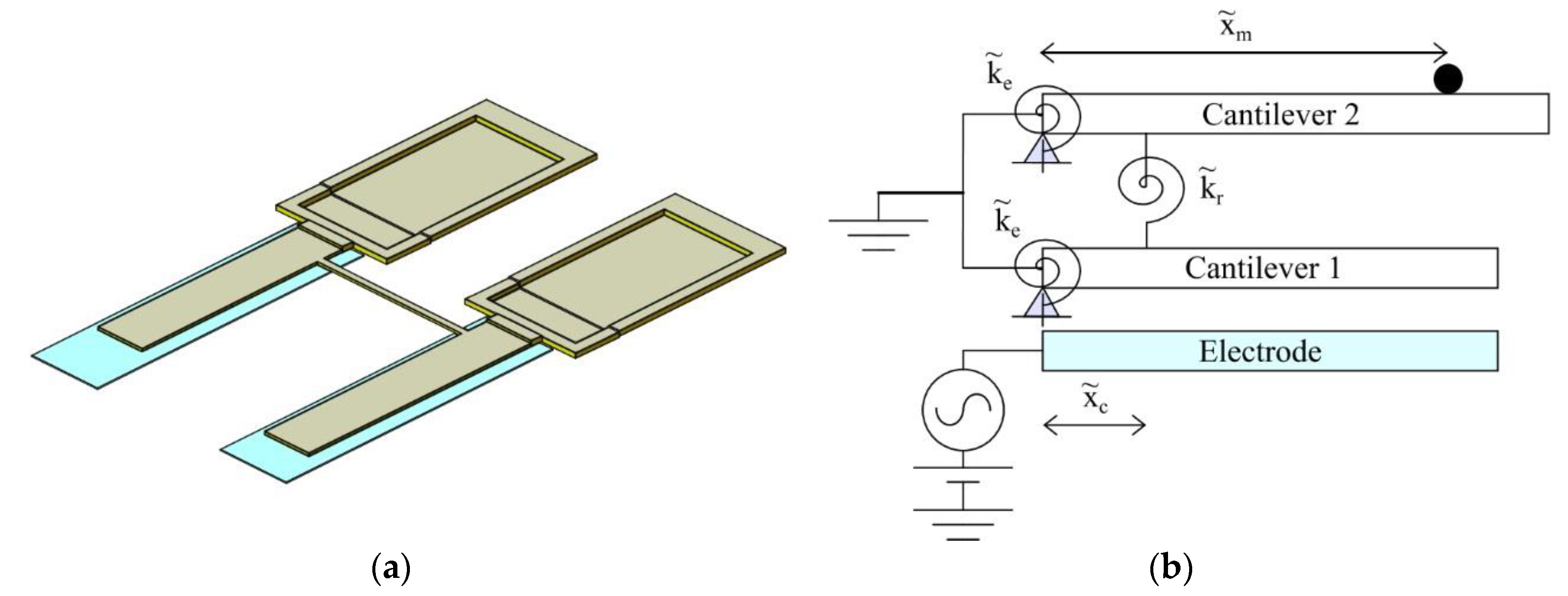
The sensor (Figure 1a) is composed of two cantilevers of 98 μm and 100 μm length, 20 μm width and 1.3 μm thick. They are coupled by a beam with 65 μm length, 3 μm width and 1.3 μm thick. To generate the vibration, the first cantilever, which is the shortest, is electrostatically actuated and a combined AC-DC voltage is applied in the bottom electrode.
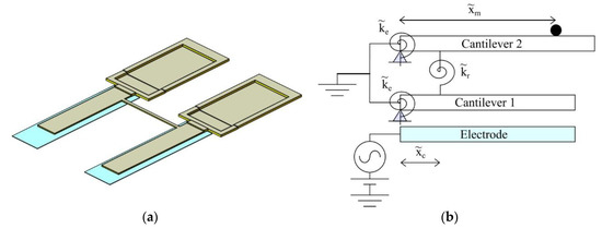
Figure 1.
(a) Coupled MEMS cantilevers for mass sensing; (b) model of two coupled beams with added point mass and electrostatic actuation.
This device is modeled with two beams with a length of L1 and L2, and connected by a rotational spring that represents the torsional stiffness of the coupling beam [3]. As this coupling beam is always near the fixed end of the cantilever, we suppose that its bending stiffness can be neglected. The real boundary condition is considered by using flexible supports, and a rotational spring is added at each cantilever. To include the mass perturbation in the model, a discrete point mass is also added on the second cantilever (Figure 1b).
Using the Euler-Bernoulli beams theory, the equation governing the bending vibration of the model in Figure 1b is given by
where primes and dots denote respectively the partial differentiation with respect to the position along the microbeam and to the time , E is the Young’s modulus, I is the moment of inertia of the cross section, and are respectively the deflection of the first and the second cantilever, and are the damping coefficient, δ is the Dirac delta function, is the coupling beam position, ρ is the material density, b is the beam width, h is the beam thickness, is the mass perturbation, is its position, ε0 is the dielectric constant of the medium, Cn is a coefficient for the edge effect in the capacitor [4], VDC and vAC are respectively the DC and AC actuation voltage, is the frequency of the AC voltage and g is the capacitor gap.
By using a third order Taylor series to expand the electrostatic force, and the following nondimensional variables
we obtain
With one mode Galerkin discretization, the deflection of each cantilevers can be expressed as
where a1s and a2s are generalized coordinates of the static deflection due to the DC component, a1(t) and a2(t) are the time varying generalized coordinates, φ1(x) and φ2(x) are the mode shapes of a single cantilever with the flexible support.
w1(x, t) = (a1s + a1(t))φ1(x); w2(x, t) = (a2s + a2(t))φ2(x)
The first and second equation in (3) are then multiplied respectively by φ1(x) and φ2(x) and they are respectively integrated from x = 0 to x = 1 and from x = 0 to x = L2/L1. In the resulting equation, all time varying terms are first dropped to determine the static deflection [5]. After this consideration, we obtain finally the following system of equations
where λ12 is the normalized eigen-angular frequency of the first cantilever.
The system of Equations (5) describes a linear oscillator coupled to an oscillator with quadratic and cubic nonlinearities and the method of multiple scales is used to solve it [6].
3. Use of an Electrostatic Force to Equilibrate the System
The use of an electrostatic force to counterbalance the defects of length difference has been already studied in [7] and a Finite Element Model was implemented in COMSOL Multiphysics® to prove its efficiency. In our case, the proposed analytical model is used and several simulations are performed with different values of the actuation voltage.
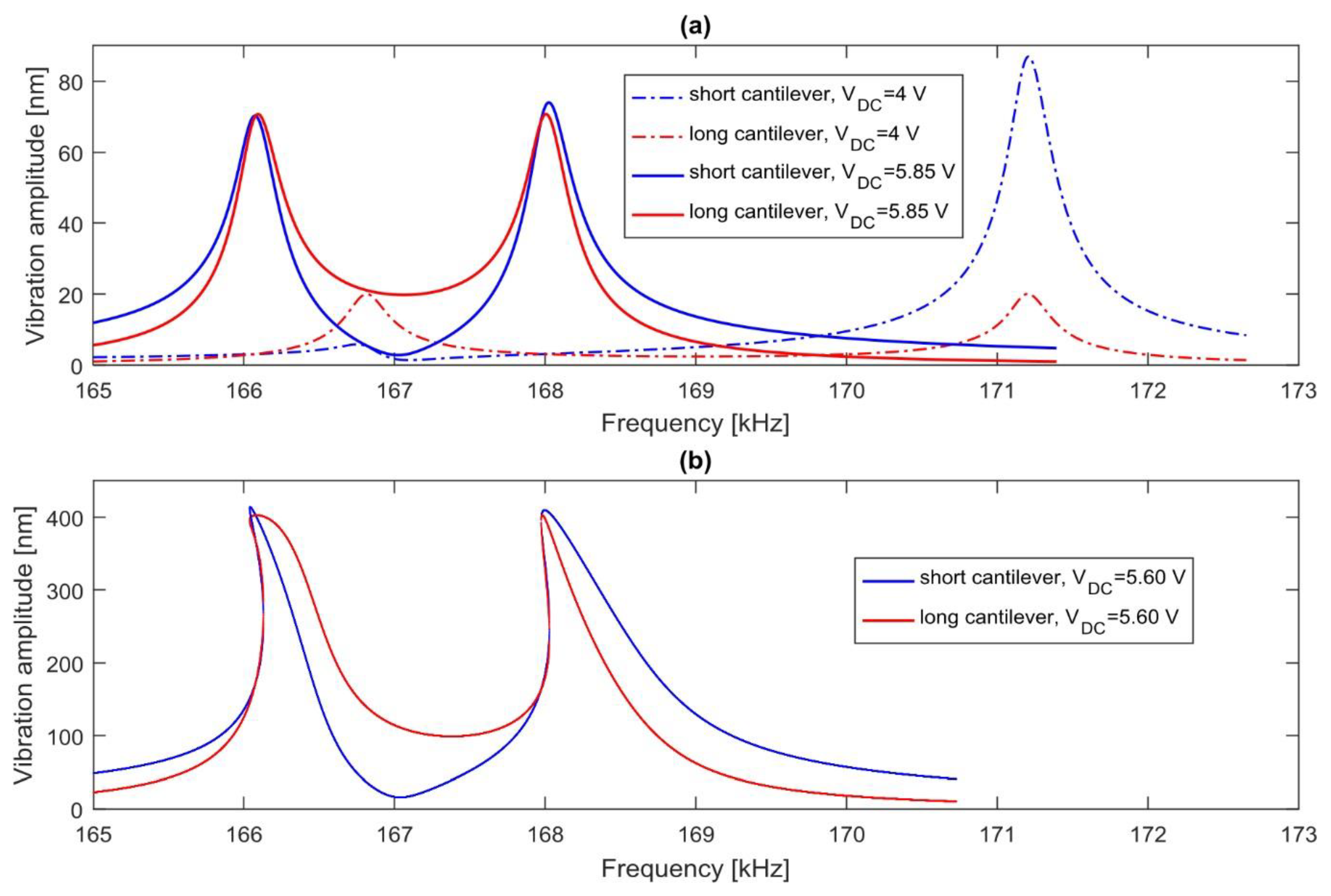
With a quality factor Q = 600 and a coupling beam at = 10 µm, the AC voltage is fixed at 10 mV, and the DC voltage is gradually increased. When its value is 4 V, the two cantilevers are still unbalanced and the vibration is localized on one of them for the in-phase mode and out-of-phase mode. When its value reaches 5.85 V, the system becomes balanced, with identical amplitudes on both cantilevers as shown in Figure 2a.
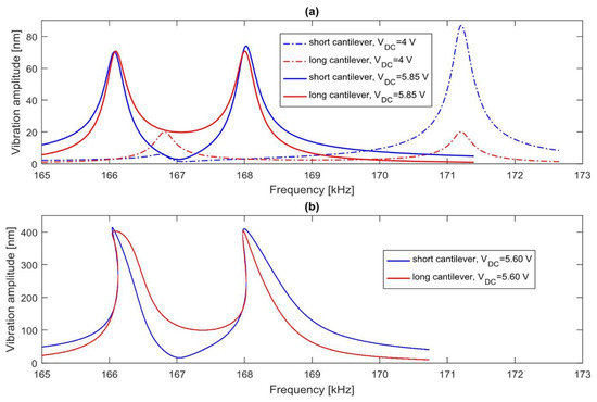
Figure 2.
Frequency responses of the two cantilevers (a) with an AC voltage of 10 mV; (b) and 60 mV.
By increasing the AC voltage at 60 mV, the vibration becomes nonlinear, and the DC voltage to counterbalance the length difference drops to 5.6 V. In addition, the frequency response in the two modes of vibration is bended to the left as shown in Figure 2b.
4. Effect of the Coupling ratio in Mass Sensing
We consider now three devices with a different coupling beam position and actuated with the required DC voltage to equilibrate them. A small relative mass of 0.1% is then added at the end of the long cantilever. By comparing the amplitude ratio of the two cantilevers in Table 1, we can notice that the vibration is more localized when the coupling beam is at 5 µm from the fixed end.

Table 1.
Amplitude ratio of the shortest cantilever (W1) and the longest cantilever (W2).
5. Conclusions
In this paper, a purely analytical model is proposed to modelize a mass sensor formed by two different mechanically coupled MEMS cantilevers. This model consists of two Euler-Bernoulli beams, which are partially clamped, and connected by a rotational spring. The equation governing its bending vibration was established and solved analytically. Several simulations performed with different voltage actuation demonstrate that the DC component can compensate the length difference, in order to equilibrate the system. With high AC voltage, the required DC voltage decreases slightly, because of the additional softening effect of electrostatic nonlinearities. By adding a relative mass of 0.1% in the balanced system, our results show that with a coupling beam near the fixed end of the cantilevers, the coupling is weaker and the sensitivity of the device is higher.
Acknowledgments
This project has been performed in cooperation with the EUR EIPHI program (ANR 17-EURE-0002).
Conflicts of Interest
The authors declare no conflict of interest.
References
- Zhao, C.; Montaseri, M.H.; Wood, G.S.; Pu, S.H.; Seshia, A.A.; Kraft, M. A review on coupled MEMS resonators for sensing applications utilizing mode localization. Sens. Actuators A Phys. 2016, 249, 93–111. [Google Scholar] [CrossRef]
- Spletzer, M.; Raman, A.; Wu, A.Q.; Xu, X.; Reifenberger, R. Ultrasensitive mass sensing using mode localization in coupled microcantilevers. Appl. Phys. Lett. 2006, 88, 254102. [Google Scholar] [CrossRef]
- Timoshenko, S. Strength of Materials. Part 1: Elementary Theory and Problems, 2nd ed.; D. Van Nostrand Co.: Toronto, ON, Canada, 1951. [Google Scholar]
- Nishiyama, H.; Nakamura, M. Form and capacitance of parallel-plate capacitors. IEEE Trans. Compon. Packag. Manuf. Technol. Part A 1994, 17, 477–484. [Google Scholar] [CrossRef]
- Bouchaala, A.; Nayfeh, A.H.; Younis, M.I. Frequency shifts of micro and nano cantilever beam resonators due to added masses. J. Dyn. Syst. Meas. Control 2016, 138, 091002. [Google Scholar] [CrossRef]
- Nayfeh, A.H.; Mook, D.T. Nonlinear Oscillations; John Wiley & Sons: Hoboken, NJ, USA, 2008. [Google Scholar]
- Walter, V.; Bourbon, G.; le Moal, P.; Kacem, N.; Lardiès, J. Electrostatic actuation to counterbalance the manufacturing defects in a MEMS mass detection sensor using mode localization. Procedia Eng. 2016, 168, 1488–1491. [Google Scholar] [CrossRef]
Publisher’s Note: MDPI stays neutral with regard to jurisdictional claims in published maps and institutional affiliations. |
© 2018 by the authors. Licensee MDPI, Basel, Switzerland. This article is an open access article distributed under the terms and conditions of the Creative Commons Attribution (CC BY) license (https://creativecommons.org/licenses/by/4.0/).