Abstract
To study the nonlinear dynamic behavior and system stability of a rubbing overhung rotor with viscoelastic and memory-effect damping and random uncertain parameters, this paper introduces a fractional-order modeling and stochastic dynamic analysis method for the nonlinear overhung rotor system with frictional impact faults. Firstly, the dynamic equations of the overhung rotor considering friction effect and fractional damping effect are established based on the transfer matrix method and fractional order derivative. Then, the time-domain response of the fractional-order dynamic equations is solved by combining the Runge–Kutta method and the continuous fractional expansion, and the steady-state response characteristics of different fractional damping are analyzed in the deterministic case. Finally, to analyze the response of the system under the effect of stochastic parameters, the sparse grid-based PCE metamodel of the system response is developed. Statistical moments, probability distributions, and sensitivity indices of the response of stochastic systems are revealed. The results of this paper provide a theoretical basis for efficient and accurate prediction of the stochastic response of nonlinear rubbing overhung rotor systems.
1. Introduction
Rotating machinery plays an important role in various engineering fields such as aerospace, marine, and electric power [1,2]. The gap between the stator and rotor is becoming smaller as rotating machinery becomes more compact. When the rotor is rotating at high speeds, typical problems such as assembly errors and mass imbalance can cause vibrations, and the amplitude can easily reach the critical value of the gap. At this point, contact may occur between the rotor and stator, often referred to as a rub-impact fault. Rub-impact faults in rotor systems can lead to system instability, blade breakage, and even catastrophic consequences [3,4,5].
To ensure the reliability, stability, and performance of rotor systems and to promote the development of rotor system design and optimization, many researchers have investigated the friction mechanism and nonlinear behavior of rubbing rotor systems [6,7]. Ma et al. [6] analyzed the dynamical characteristics of the rotor–stator system under different rubbing forms. Guan et al. [8] investigated the nonlinear dynamic characteristics of an eccentric rotor system with friction for different misalignment angles and speeds. Shang et al. [9] studied the global response characteristics of a rotor–stator rubbing system considering dry friction effects. Chipato et al. [10] studied the effect of friction coefficient and eccentricity on the nonlinear dynamics of a rubbing-overhung rotor. I. C. Begg [11] analyzed a simple flexible overhung rotor and investigated the stability of friction-induced rotor whirls. The above study provides insight into the dynamics and system stability of friction faults in integer-order damped rotors.
In complex engineering environments, various uncertainties inevitably exist [12,13,14,15]. To achieve a robust assessment, their impact on the dynamics of rotating mechanical systems should not be ignored. In recent years, several researchers have begun to focus on uncertainty quantification in the field of rotor dynamics [16,17]. Probabilistic models [18,19] have become the most widely used models based on known data describing the uncertainty of parameters through probabilistic and statistical methods. Common approaches in the quantification of probabilistic uncertainty include Monte Carlo simulation [20,21] and surrogate modeling [22,23,24]. Zhang et al. [16] used non-intrusive generalized polynomial chaos expansion (gPCE) with unknown deterministic coefficients for uncertainty and sensitivity analysis of the Jeffcott rotor system with fixed-point frictional impact and multiple uncertain parameters. Ma et al. [25] used an advanced Kriging surrogate model for uncertainty quantification and reliability analysis of rotor–stator rub impacts. Kartheek et al. [19] evaluated the effect of perturbations in key system parameters on the dynamic characteristics of a flexible rotor with localized contact and analyzed the effect of uncertainty on the stochastic response of the rotor–stator system using a gPCE method. Yang et al. [26] investigated stochastic bifurcation and chaos in a rub-impact rotor system with random stiffness under random excitation.
The behavior and properties of various linear and nonlinear systems have been explored in-depth in the traditional study of integer-order rotor systems. However, as the research progressed, integer order calculus was found to have certain limitations in describing certain complex dynamical systems. To address these problems, researchers have turned to the study of fractional dynamical systems [27,28,29,30]. Alhejaili et al. [31] conducted a soliton approximation analysis of the fractional forced Korteweg-de Vries equation in fluids and plasmas using two novel techniques. Meanwhile, Noor et al. [32] applied the Aboodh transform framework to solve both linear and nonlinear time-fractional partial differential equations, providing a comparative analysis. Fractional-order calculus not only describes the memory effects and genetic properties of the system more accurately but also reveals more about the dynamical behavior and complexity [33,34]. Cao et al. [35] discussed the nonlinear dynamic characteristics of a rub-impact rotor system with fractional damping and revealed the significant influence of a fractional order on the complex dynamical behavior of the system. Smyth et al. [36] established the corresponding coupled dynamics model by introducing the fractional viscoelastic support and analyzed, for the first time, the influence of viscoelasticity on the global dynamics of rotor–stator rubbing. Yan et al. [37] presented a fractional-order modeling and dynamic analysis of a bending–torsion coupled generator rotor shaft system with multiple faults, including rubbing. Although there have been a number of advances in the study of fractional-order rubbing rotors, most of the studies have focused on deterministic analysis. As a result, there is still an obvious gap in the study of uncertainty quantification in fractional-order rubbing rotor systems.
Given the shortcomings and challenges of existing stuiesy, we were motivated to investigate the fractional-order modeling of friction-shock rotor systems with overhung discs and to analyze the stochastic properties of the system by the non-intrusive PCE. The main points of this study are as follows. First, a fractional-order model of the friction rotor system is developed to capture the complexity of the system behavior more accurately based on the rigid body assumption, ignoring the influence of the rotational axis. Second, the sparse grid-based PCE (SGPCE) is used to explore the response characteristics, reliability, and sensitivity metrics of the system under the effect of mutually independent stochastic parameters. Third, the performance of the system under different cases is evaluated to determine its robustness and stability.
This paper is structured as follows. Section 2 outlines the fractional-order dynamics model and numerical approximation of the nonlinear rubbing overhung rotor. Section 3 describes the sparse grid-based PCE method that is used for uncertainty analysis. The dynamic response under deterministic and stochastic uncertainties is presented and discussed in Section 4. Section 5 summarizes the main findings and implications for future research, and it concludes with the significance of this study.
2. Fractional-Order Modeling of the Rubbing Overhung Rotor
2.1. Equation of Motion for the Rubbing Rotor
This study investigates the dynamics of a hollow shaft rotor with a cantilevered disk, as illustrated in Figure 1. Derived from the simplification of an oxygen pump, this system epitomizes the typical cantilever configuration widely adopted in industry [38]. It is supported by two isotropic linear bearings with identical stiffness in the x and y directions. The disk has a mass of , and its polar moment of inertia and diameter moment of inertia are denoted as and , respectively. Damping effects are integrated into viscous damping, represented by . The stator is mounted close to the mass disk, and the gap between the rotor and stator is denoted by . They come into contact when the vibration amplitude of the rotor reaches its limit. The reactive forces during contact are depicted in Figure 2.
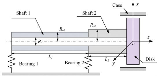
Figure 1.
Schematic diagram of the rotor structure.
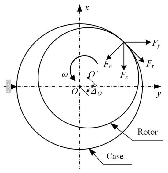
Figure 2.
Description of rotor–stator contact.
For a prescribed gap , if the radial deviation of the geometric center of the disk is less than the clearance value, then , and the rotor system will be in linear vibration. When , the friction impact force can be expressed as
where is the contact stiffness, and is the friction coefficient associated with the tangential force of impact . There are other friction models apart from the one used in this work, such as the Karnopp model and others [39,40]. Following a standardized approach, the friction impact force on the rotor can be projected onto the coordinates as
where is the Heaviside function
In this study, to facilitate the derivation of the equations of motion (EOM) for the collision-friction rotor system, the Transfer Matrix Method (TMM) [41,42,43] is employed to calculate the stiffness parameters of the rigid disk. In the TMM, each characteristic cross-section (node) has four degrees of freedom (DOFs), namely two translational displacements and two rotational angles, as depicted in Figure 1. Its main advantage lies in the fact that regardless of the number of DOFs in the rotor system, the dimensions of the calculation matrix remain constant. The disk can be modeled by external increments of the motion state vector. The displacement vector of the disk is represented as , where and are translational displacements, and and are rotational displacements about the and axes, respectively. When considering the mass of the elastic shaft, the time-varying EOM for the rotor system can be represented as
where and are the nonlinear forces induced by friction, is the angular velocity, and is the eccentricity on the disk. The stiffness parameters are elements derived from the left to the right of the rotor using the TMM.
2.2. Fractional Calculus and Approximation Schemes
While the integer-order dynamic model is depicted in Equation (4) with mature theoretical foundations, integer-order calculus may not accurately capture certain complex behaviors and phenomena, especially those involving long-term memory or non-local effects. Fractional calculus provides a more flexible framework capable of exhibiting the complex frequency dependency of damping materials, with many successful applications in mechanical engineering. First, it is necessary to introduce the definition, properties, and computations of fractional calculus.
Commonly used definitions of fractional calculus in the mathematical community include Riemann-Liouville (R-L) fractional calculus, Grünwald-Letnikov (G-L) fractional calculus, Caputo fractional calculus, and Riesz fractional calculus [44,45]. Among the various definitions of fractional calculus, the ones most frequently utilized by experts and scholars are R-L and G-L.
According to the definition of G-L calculus, for any real number , if the function has an -th order derivative on the interval , then the fractional -order derivative of the function is denoted as
where is a binomial coefficient. The other parameters are as follows: represents the fractional order, is the calculation step size, and denotes the integer part during the computation process. represents the gamma function. When , Equation (5) denotes a differentiation operation, and when , Equation (5) denotes an integration operation.
The R-L definition of fractional calculus is an improvement on the G-L definition, primarily simplifying the complex computations involved. The specific definition of fractional differentiation is expressed as
where . When , Equation (6) can be specially represented as
As shown in the equation above, fractional calculus calculations in the time domain are highly complex. Therefore, many researchers have continuously simplified the solutions to fractional calculus, such as introducing the Laplace transform into the solution of fractional-order equations. The Laplace transform of the fractional differentiation function is expressed as
where is the function in the time domain, is the Laplace transform of , and is a complex variable. If all initial conditions are zero, the Laplace transform of fractional calculus can be simplified to
It can be seen from Equation (9) that the numerical computation of the factor is crucial in solving fractional calculus equations.
In the practical solution of fractional calculus, there are two main approaches: analytical and numerical. However, due to the complexity and computational difficulty of analytical methods, as well as their significant operational challenges, they are less commonly used. The equations are usually solved numerically, and the first step is to replace the fractional calculus operator with a generating function , and then rationalize the generating function expansion.
Based on the Euler operator, direct discretization of the fractional calculus operator yields
Then, using the continuous fractional expansion (CFE) transformation [46,47], the discretized result is
where denotes the CFE transformation of the function , and represent the orders of approximation, and and are polynomials of degree and , respectively. Typically, values of , , and can be set to be equal. In the numerical analysis below, the values of and in the approximate equation are set to 10.
When considering fractional-order damping in the dynamic analysis of a frictional rotor, the damping forces and on the left-hand side of Equation (4) can be represented using fractional derivative as
where is the order of the fractional damping. Combining Equations (4) and (12) yields the state-space equation for the fractional-order nonlinear rubbing overhung rotor system as follows:
For the state-space equation in Equation (13) containing fractional-order derivatives, we utilize the Euler generating function and the CFE method introduced in this section for discrete approximation. First, the fractional calculus operator in Equation (10) is discretized using the Euler generating function. Then, the CFE method is used to approximate the discretized fractional calculus operator. Finally, the fourth-order Runge–Kutta method is utilized to solve the transformed equations to obtain the response of the fractional-order dynamical system.
Please note that the friction model during the contact in the rubbing process can also be fractional, and the readers are referred to relevant studies [48,49].
3. Stochastic Analysis of the Fractional Nonlinear Vibrations
The rub-impact between the rotor and the casing involves three key parameters: clearance, contact stiffness, and friction coefficient. They are fundamentally influenced by uncertainties arising from rotor blade wear, material degradation, and assembly errors. Additionally, the support stiffness and material characteristics of the rotor system are uncertain. Considering these uncertain parameters in the motion equations of the rubbing rotor system leads to the transformation of originally deterministic responses into uncertain ones. The uncertainty in responses can have profound effects on system operation, especially when considering the nonlinear rubbing rotor system with fractional-order damping. Therefore, it is necessary to quantify the uncertainty in system response through appropriate methods to enhance system stability and predictability. PCE is a widely used method for probabilistic uncertainty modeling.
3.1. Polynomial Chaos Expansion
The concept of PCE was initially proposed by Wiener [50]. In Wiener’s chaos theory, orthogonal polynomials were suggested to express second-order stochastic processes. Some early studies utilized the Hermite PCE to solve stochastic differential equations and demonstrated its effectiveness for Gaussian or certain non-Gaussian random inputs. However, for general non-Gaussian random inputs, the convergence rate may not be optimal. Xiu et al. [51,52] extended Hermite polynomials to the Wiener–Askey family of polynomials, proposing the gPCE. They argue that the “optimal choice” can be made by choosing a polynomial basis based on the random input distribution in Table 1. They further proved that with this optimal selection, exponential convergence rates could be achieved.

Table 1.
Common distributions, corresponding terms, and orthogonal polynomials.
Assuming that the response of the fractional-order dynamical system in Equation (13) is given by , where is the model input, is time, and is the model output, maps the input to the output . If input parameters are uncertain, the output will be stochastic. Generally, PCE can approximate the random output as an orthogonal polynomial expression of predefined random variables
where is defined as the expansion coefficient vector with respect to time , is the Wiener–Askey polynomial of d-dimensional random variables , and is the multi-index. The N-variable polynomial is constructed as the product of these single-variable polynomials , that is,
where is an orthogonal polynomial of order with respect to the -th dimensional parameter . The order of is defined as .
In practice, the approximate computation is performed in a finite-dimensional space with a finite sum. Therefore, it is necessary to truncate the infinite expansion in Equation (14). Common truncation strategies include tensor product, total degree, and hyperbolic cross, as well as other sparse basis strategies. The total degree truncation strategy truncates the expression in Equation (14) based on the total order of the polynomial as
The choice of truncation order is based on accuracy requirements. For a “”-order (the highest order of polynomial chaos) d-dimensional (the number of random variables) PCE, the total number of polynomial basis terms is
3.2. Sparse Grid for Solving Coefficients
An important aspect of PCE is determining the expansion coefficients . Generally, there are two types of methods for estimating coefficients: intrusive methods and non-intrusive methods [53]. Intrusive methods involve transforming the original dynamic model into a set of equations (often coupled) where the expansion coefficients are unknown. The coefficients are then obtained by solving the resulting equations. This process is often cumbersome and sometimes impractical, especially for highly complex nonlinear problems. In contrast, non-intrusive methods do not require model transformation. When the dynamic form is complex and deriving equations for expansion coefficients is difficult, the superiority of non-intrusive methods becomes apparent. Non-intrusive methods include stochastic collocation methods [54] and regression-based methods [55]. This study uses the stochastic collocation method with a rigorous mathematical proof.
The inner product of any basis function in the expansion with the approximate response function can be expressed as
where notation represents the inner product, which can be expressed as
According to the orthogonality property of PCE, Equation (18) can be expressed as
Therefore, the coefficients of each term of the polynomial basis function can be obtained from the following equation:
Gaussian quadrature, as a standard tool for numerical integration, represents the coefficients in a simple weighted sum form:
where is the joint probability distribution of the vector ; the weights and the set of quadrature points (experimental design) are derived from Lagrange polynomial interpolation, ensuring the accuracy of the integration evaluation of polynomial complexity functions. The quadrature weights and quadrature points are uniquely determined by the marginal independent components of the input random vector and they correspond to the roots of the respective polynomial basis functions reported in Table 1. Standard multivariate Gaussian quadrature is achieved through the tensor product of univariate quadrature rules.
is a one-dimensional Gaussian quadrature rule obtained from the interpolation points of the orthogonal polynomial and the corresponding weights , which can be expressed as
The number of quadrature points rapidly increases with the number of input variables. For instance, selecting the maximum polynomial degree will require quadrature points in each dimension, resulting in in Equation (22). This is known as the curse of dimensionality.
The Smolyak sparse grid interpolation is a novel tool for handling high-dimensional integrals, serving as an alternative to the original tensor product multidimensional quadrature. When constructing sparse interpolation points using the Smolyak algorithm, the quadrature points on the one-dimensional axis are fully utilized, while as many points as possible are retained in directions with N > 1. The method is essentially a linear combination of tensor product nodes. The number of sparse nodes is significantly reduced compared to the tensor product quadrature, thus reducing the dependence on the number of dimensions. Based on Smolyak’s sparse grid theory, the high-dimensional quadrature based on the Smolyak algorithm can be defined as
where is the index of the multi-dimensional quadrature points; k denotes the level of the sparse grid quadrature. Thus, all the quadrature points contained in the classical Smolyak sparse grid are
The number of points is
where l = k + d and duplicate points are counted multiple times.
In the same dimension, sparse grid nodes are significantly fewer in number compared to tensor product nodes. The SGPCE somewhat alleviates the curse of dimensionality faced by the full grid-based PCE (FGPCE).
4. Results and Discussion
First, the deterministic response is illustrated by describing the rubbing rotor system without uncertainty conditions, thus providing an initial impression of its dynamic behavior. Then, based on the deterministic analysis, the effect of parameter uncertainty on the system dynamics is investigated by stochastic analysis, thus providing a deeper understanding of the robustness and reliability of the rotor system in practical applications.
4.1. Deterministic Analysis
In this subsection, we analyze the response of the fractional-order overhung rotor in the deterministic case. The parameters of the rubbing overhung rotor system are as follows: the contact stiffness, friction coefficient, and gap value between the rotor/stator are , , and , respectively; the lengths of shaft 1 and shaft 2 are 0.3 m and 0.12 m, respectively; the outer radii of shaft 1 and shaft 2 are 0.02 m and 0.03 m, respectively, while the inner radii are both 0.005 m; the mass of the disk is 8.4 kg, and the polar and diameter moments of inertia are 0.0695 kg/m2 and 0.0357 kg/m2, respectively; the stiffnesses of bearing 1 and bearing 2 are and , respectively; the viscous damping factor of the disk is 120.
Based on the deterministic model and numerical simulations, the steady-state orbit, radial deflection, and spectrum of the geometric center of the disc at ω = 200 rad/s are analyzed for different damping orders. In the steady-state analysis, the initial period is ignored to eliminate transient effects. The steady-state deflection curves and axial orbits for orders of α = 1, 0.8, and 0.6 are shown in Figure 3 and Figure 4, respectively. It degrades to the integral order case for α = 1. The comparison between fractional calculations and those of the integral order are incorporated throughout all the discussions.

Figure 3.
Radial deflection over 500–505 periods at three different orders.
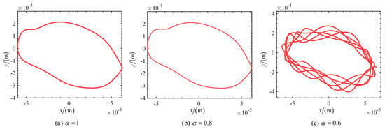
Figure 4.
Orbits over 500–505 periods at three different orders.
From Figure 3 and Figure 4, the steady-state time-domain curves and the axial orbits show significant nonlinearities. The time response curve becomes complex and is no longer a simple sine or cosine wave, while the axial estimates are no longer circular or elliptical. This indicates the presence of multiple frequency components in the response beyond the fundamental frequency. The main reason for this is that the unbalance and asymmetry of the system can lead to irregular forces in the rotor during rotation, and that rub and impact forces introduce high-frequency components and transient responses. It is also evident that after 500 cycles, the system responses of orders and have entered the steady state, while the system of order is still in the unsteady state. To explore the steady-state response of the 0.6 order system, we analyzed the system response after a longer time. Figure 5 shows the center orbit and spectrogram of radial deflection for the 0.6-order system for periods 1000–1020 and 2000–2020.
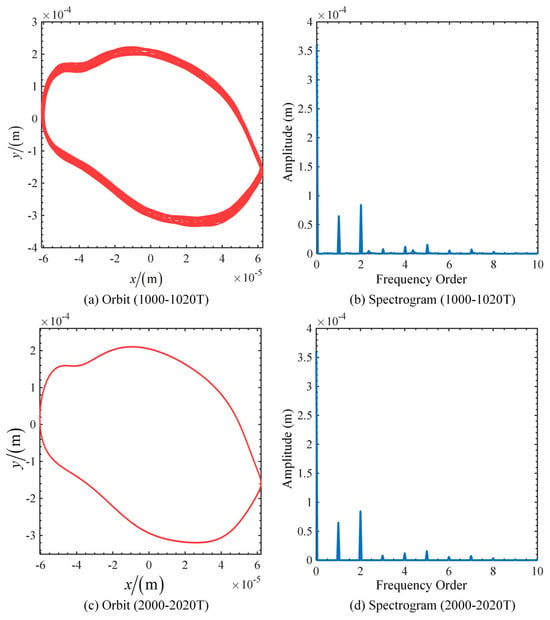
Figure 5.
Orbit and spectrograms of deflection for 0.6-order systems in the period ranges 1000–1020 and 2000–2020.
From Figure 3c, Figure 4c and Figure 5, we can draw the following phenomena and conclusions. There are significant fluctuations in the system response during the 500–505 periods, which may be attributed to the fact that the system is subjected to a large perturbation in the initial stage, the internal energy distribution has not yet been stabilized, and the nonlinear effects and frequency components have not yet been sufficiently attenuated. As the number of periods increases, the system response enters a transition phase and gradually tends to a steady state during the 1000–1020 periods. In the 2000–2020 periods, the system response fully enters the steady state and exhibits a stable vibration mode. Multiple frequency components are represented in the spectrum for both steady-state and non-steady-state responses. In the steady state, the frequency components are all integer multiples of the fundamental frequency, whereas in the non-steady state, there are non-integer multiples of the components. By analyzing the rubbing overhung rotor system with 0.6-order fractional-order damping, we find that the system response exhibits different dynamic characteristics in different period ranges. The system response is unstable in the initial stage, and the system gradually converges to a steady state over time and eventually enters a steady state over a long period.
To investigate the response characteristics of the 0.4-order system, numerical simulations and analyses were run for a longer period. The radial deflection curves, orbit, and spectrograms for the system with after 20,000 periods are shown in Figure 6. It can be seen from the figure that the response of the system fails to reach a steady state after a long period of running. The time response curves, axial orbits, and spectrograms show complex irregular characteristics. This indicates that low-order fractional-order damping and rubbing impacts have a significant effect on the dynamic behavior of the rotor system, especially in the case of low-order fractional damping, where the system exhibits a complex chaotic behavior.
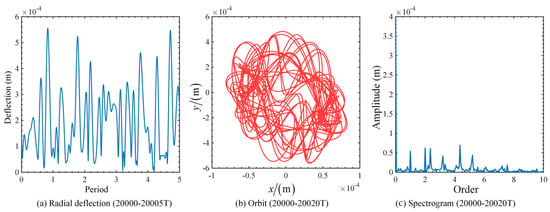
Figure 6.
Radial deflection curves, orbits, and spectrograms of the system after 20,000 cycles for .
Based on the above deterministic analysis, it is clear that the response of the system under the effect of a rub impact exhibits a significant nonlinearity, which contains high harmonics and combined frequencies. Moreover, as the order of damping decreases, it takes a longer time for the rub-impact rotor system to reach a steady state. Even when the order is reduced to a certain degree, the system may enter into a chaotic state. The main reason for these phenomena is due to the following:
- (1)
- As the order decreases, the damping effect is weakened, resulting in less efficient energy dissipation and allowing for more energy to be retained in the system. This energy accumulation effect may make it difficult for the system to reach a steady state after a long period of operation.
- (2)
- The lower fractional-order derivatives imply that the system has a strong memory effect, allowing the system to maintain a large amplitude of vibration when it is excited. This strong memory effect allows the system to maintain a complex dynamic behavior over long periods.
- (3)
- The introduction of fractional-order derivatives may change the dynamics of the system, including its intrinsic frequency and damping ratio. When the damping effect is weakened, the system is more likely to reach the resonance condition.
4.2. Stochastic Uncertainty Quantification
In practical situations, uncertainties in the system parameters are inevitable. Errors during manufacturing and installation, material aging, and changes in the operating environment will lead to changes in the density, modulus of elasticity of the material, and support stiffness. We select the support stiffness and , the density of the rotor shaft, and Young’s modulus of the rotor shaft as the stochastic uncertainty parameters. Each parameter follows a normal distribution with an expectation value of the deterministic value in Section 4.1 and a coefficient of variation of 1%.
We establish the sparse grid PCE metamodel for uncertainty analysis and compare the results with MCS. Figure 7 gives the expectation and standard deviation of the steady-state deflection obtained from the 4th-order SGPCE and MCS for the three cases .
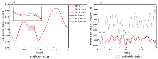
Figure 7.
The first two statistical moments of radial deflection in one period for three fractional damping cases obtained by MCS and 4th-order SGPCE.
As can be seen in Figure 7, the expectations of the responses of the three fractional damping systems are almost the same for the same uncertainty, while the standard deviations are different. The standard deviation, in general, increases as the order of the fractional order derivative decreases. This is consistent with the results of the deterministic analysis, again indicating that the order of damping changes the characteristics of the system response. Furthermore, the expectation and standard deviation obtained from the 4th-order SGPCE are almost identical to those obtained from the MCS when = 1 and 0.8. However, the 4th-order SGPCE requires only 494 sample points, the full grid PCE requires 625 sample points, and the MCS requires 3000 sample points. This indicates that SGPCE is more efficient than traditional FGPCE and MCS and is accurate. As the order A decreases to 0.6, the results of the 4th-order SGPCE are no longer accurate, so we use the 4th-order FGPCE. The 99.97% confidence intervals for the radial deflections obtained by the 4th-order FGPCE and MCS for a = 0.6 are shown in Figure 8.
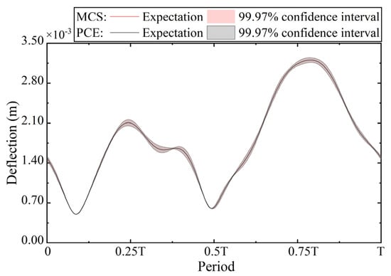
Figure 8.
The 99.97% confidence interval of radial deflection obtained from the 4th-order FGPCE and MCS for = 0.6.
From Figure 8, the results obtained from the 4th-order FGPCE are almost identical to those obtained with the MCS, both in terms of expectation and confidence intervals. This indicates that the degree of nonlinearity and instability of the system response increases as the order of the fractional-order derivatives decreases, and thus, the order of the PCE must be increased or a full grid quadrature must be used to better capture the complex dynamics of the system response. The width of the confidence interval for radial deflection reflects the uncertainty of the system response under different parameter perturbations. The wider the confidence interval, the greater the variability of the system response. From the figure, we know that the variability of radial deflection is greater at the peaks and valleys. Therefore, more attention should be paid to the response at peaks and valleys during system analysis and optimization.
To quantify the volatility of the stochastic response of the rubbing overhung rotor system in the three fractional damping cases, we present in Figure 9 the coefficient of variation curves of the deflections obtained by MCS and PCE for the three cases. The results of the MCS are in agreement with those of the PCE for all three cases. The maximum coefficient of variation for all three cases occurs at the same moment, but the maximum coefficient of variation increases as the order decreases and reaches almost 1.8% when = 0.6. The coefficient of variation can be used as an index of robustness, and the analysis of the coefficient of variation shows that the robustness of the system decreases with the decrease in the order. This also explains the reason why it is difficult for the system to reach a steady state as the order decreases.
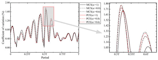
Figure 9.
Coefficient of variation curves of deflections obtained from MCS and PCE for the three cases.
The probability density cloud of the radial deflection and the point cloud plot of the axial orbit of the steady-state response when the order of damping is 0.6 are given in Figure 10. The probability density cloud allows for a visualization of the probability distribution characteristics of the radial deflection in the time domain and identifies the high-probability regions as peaks and valleys. Figure 10b shows that the basic shape of the axial orbit of the rotor in the uncertainty case is similar to the deterministic result. However, the axial orbit in the uncertainty case has a width, and this width range indicates the possible interval of the response. In summary, the vibration modes of the 0.6-order damped system under 1% uncertainty are almost unchanged, except for some fluctuations in the values of the response.
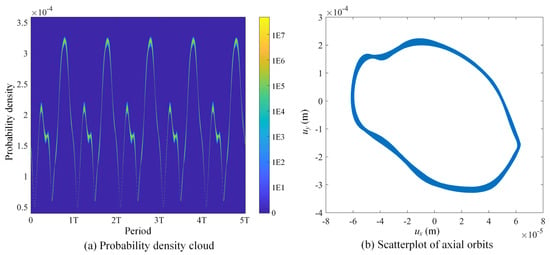
Figure 10.
Probability density cloud of deflection and point cloud of axial orbit for .
To obtain a clearer insight into the probability distribution of the peak steady-state response of the rubbing-impact rotor system for the three different damping cases, we obtained the PDF curves and CDF curves shown in Figure 11 based on the 3000 sample points from the PCE meta-model and the 3000 sample points from MCS. It can be seen from the figure that the PDF and CDF curves obtained from the PCE metamodel for the three different damping cases are almost identical to those obtained by solving the fractional-order differential equations via the MCS method. This result demonstrates the accuracy and effectiveness of the PCE metamodel in analyzing the steady-state response of the fractional-order rubbing rotor system. Regardless of the damping case, the PDF of the steady-state response peaks exhibits a typical bell-shaped curve, indicating that the system response peaks are concentrated in a certain range and gradually decrease to both sides. The CDF exhibits a typical S-shaped curve. From the shapes of the PDF and CDF curves, it can be seen that the peaks of the steady-state responses for the three different damping cases approximately obey a normal distribution, despite the fact that the system has complex fractional-order damping and rubbing effects.
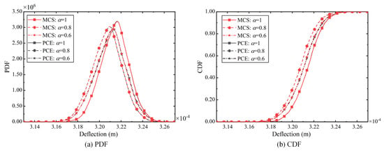
Figure 11.
PDF and CDF curves of peak deflection.
The sensitivity indices of the peak deflection with respect to the four random parameters for the three cases are shown in Figure 12. MCS-based Sobol sensitivity analysis is difficult to implement due to the large number of analyses required and the long simulation time required for each deterministic analysis to reach a steady state. The sensitivity metrics given here are obtained directly using the coefficients of PCE. It is known from the sensitivity analysis that the support stiffness is the key parameter affecting the peak deflection. Regardless of the damping case, the change in the support stiffness has the most pronounced effect on the system response because is the closest support to the mass disk. The Young’s modulus of the rotor shaft has the next best effect on the system response since the Young’s modulus of the shaft also affects the stiffness of the system. The density of the rotor shaft has a relatively small effect on the peak deflection of the system because it only affects the mass and inertia characteristics of the rotor. The effect of the support stiffness is almost negligible, mainly because Support 1 is the furthest away from the mass disk and the energy attenuation in the vibration transmission path.
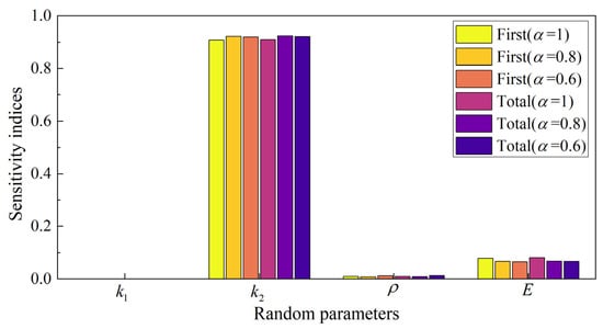
Figure 12.
Sensitivity metrics of peak deflection with respect to 4 random parameters in three cases.
The findings of the present study on fractal and uncertain dynamics of rubbing rotor systems help to clarify unexplainable behaviors found in practice. On the one hand, the effects of uncertain parameters are identified since the uncertainties are inevitable, as explained in the introduction. The sensitivity studies reveal which parameters will have the greater impact on the dynamics. That will help engineers to prioritize certain design parameters in the design and optimization or maintenance of a rotor system. On the other hand, the incorporation of fractal characteristics in the damping will benefit the understanding of rotors composed of typical materials that have memory effects. To sum up, this work can provide practical values to the industry for a more insightful understanding of dynamics and more efficient design or maintenance of rotor systems.
5. Conclusions
In this paper, the dynamic behavior and system stability of a nonlinear overhung rotor with rubbing impact faults are systematically investigated by introducing fractional-order modeling and stochastic dynamic analysis methods. The dynamic equations of the overhung rotor considering the rubbing effect and fractional damping effect are established. The time-domain response of the fractional-order dynamic equations is solved by combining the Runge–Kutta method and the continuous fractional expansion method. The steady-state response properties of the system of different fractional orders under deterministic and stochastic parameters are explored in depth through numerical simulations and analysis. The study shows that the rubbing impact leads to a significant nonlinearity of the system response containing the higher harmonics. As the damping order decreases, the time for the system to reach the steady state is significantly prolonged due to the weakening of the damping effect and the enhancement of the memory effect. At very low orders, the system may even enter a chaotic state. It can be seen that fractional-order modeling, which is necessary for materials possessing memory characteristics, reveals more complex behaviors than the traditional integral-order modeling of rotor systems. In the stochastic uncertainty analysis, the results show that PCE has higher efficiency. However, for low-order damped systems, SGPCE may not be able to capture the system response characteristics accurately. In addition, the analysis of statistical quantities such as statistical moments and probability distributions reflects the characteristics of the system response under the action of stochastic parameters. The sensitivity analysis reveals the level of influence of the stochastic parameters on the system response. The results of this paper provide a theoretical basis for the prediction of the response of nonlinear rubbing overhung rotor systems and reveal the laws of the system parameters and fractional order on the dynamic behavior. The findings are of significance in the design and optimization of rotor systems.
In the future, experimental validations of the findings will be carried out. Moreover, the nonlinear frequency responses and bifurcations of the rub-impact rotor with fractal damping and uncertainties will be investigated.
Author Contributions
Conceptualization, C.F., H.Z. and F.W.; methodology, C.F.; software, H.Z. and F.W.; validation, Z.Z. and Y.Z.; formal analysis, J.M.; investigation, H.Z. and F.W.; resources, Z.Z.; data curation, Y.Z.; writing—original draft preparation, H.Z. and F.W.; writing—review and editing, C.F., J.M. and Z.Z.; visualization, Y.Z.; supervision, C.F.; project administration, J.M.; funding acquisition, J.M. and C.F. All authors have read and agreed to the published version of the manuscript.
Funding
This research was funded by the National Natural Science Foundation of China, grant number 52205089; the Guangdong Basic and Applied Basic Research Foundation, grant number 2023A1515012154; and the Fundamental Research Funds for the Central Universities, grant number G2023KY05105.
Data Availability Statement
Data are available upon reasonable requests.
Conflicts of Interest
The authors declare no conflicts of interest.
References
- Lavrenko, I.; Popov, A.; Seleznov, I.; Kiyono, K. Fractal Analysis of the Centrifuge Vibrograms. Fractal Fract. 2024, 8, 60. [Google Scholar] [CrossRef]
- Zhao, B.; Xie, L.; Li, H.; Zhang, S.; Wang, B.; Li, C. Reliability Analysis of Aero-Engine Compressor Rotor System Considering Cruise Characteristics. IEEE Trans. Reliab. 2020, 69, 245–259. [Google Scholar] [CrossRef]
- Ma, H.; Wu, Z.; Zeng, J.; Wang, W.; Wang, H.; Guan, H.; Zhang, W. Review on Dynamic Modeling and Vibration Characteristics of Rotating Cracked Blades. J. Dyn. Monit. Diagn. 2023, 2, 207–227. [Google Scholar] [CrossRef]
- Almutairi, K.M.; Sinha, J.K. A Comprehensive 3-Steps Methodology for Vibration-Based Fault Detection, Diagnosis and Localization in Rotating Machines. J. Dyn. Monit. Diagn. 2024, 3, 49–58. [Google Scholar] [CrossRef]
- Fu, C.; Zhu, W.; Zheng, Z.; Sun, C.; Yang, Y.; Lu, K. Nonlinear Responses of a Dual-Rotor System with Rub-Impact Fault Subject to Interval Uncertain Parameters. Mech. Syst. Signal Process. 2022, 170, 108827. [Google Scholar] [CrossRef]
- Ma, H.; Zhao, Q.; Zhao, X.; Han, Q.; Wen, B. Dynamic Characteristics Analysis of a Rotor–Stator System under Different Rubbing Forms. Appl. Math. Model. 2015, 39, 2392–2408. [Google Scholar] [CrossRef]
- Prabith, K.; Krishna, I.R.P. The Numerical Modeling of Rotor–Stator Rubbing in Rotating Machinery: A Comprehensive Review. Nonlinear Dyn. 2020, 101, 1317–1363. [Google Scholar] [CrossRef]
- Guan, H.; Ma, H.; Yang, Y.; Wang, P.; Xu, H.; Xiong, Q.; Liu, M. Vibration Characteristic Investigation of an Eccentric Rotor System with Rubbing. Mech. Based Des. Struct. Mach. 2023, 52, 6275–6304. [Google Scholar] [CrossRef]
- Shang, Z.; Jiang, J.; Hong, L. The Global Responses Characteristics of a Rotor/Stator Rubbing System with Dry Friction Effects. J. Sound Vib. 2011, 330, 2150–2160. [Google Scholar] [CrossRef]
- Chipato, E.; Shaw, A.D.; Friswell, M.I. Frictional Effects on the Nonlinear Dynamics of an Overhung Rotor. Commun. Nonlinear Sci. Numer. Simul. 2019, 78, 104875. [Google Scholar] [CrossRef]
- Begg, I.C. Friction Induced Rotor Whirl—A Study in Stability. J. Eng. Ind. 1974, 96, 450–454. [Google Scholar] [CrossRef]
- Fu, C.; Zheng, Z.; Zhu, W.; Lu, K.; Yang, Y. Non-Intrusive Frequency Response Analysis of Nonlinear Systems with Interval Uncertainty: A Comparative Study. Chaos Solitons Fractals 2022, 165, 112815. [Google Scholar] [CrossRef]
- Li, H.N.; Wang, W.; Lai, S.K.; Yao, L.Q.; Li, C. Nonlinear Vibration and Stability Analysis of Rotating Functionally Graded Piezoelectric Nanobeams. Int. J. Struct. Stab. Dyn. 2024, 24, 2450103. [Google Scholar] [CrossRef]
- Zhao, H.; Li, F.; Fu, C. An ε-Accelerated Bivariate Dimension-Reduction Interval Finite Element Method. Comput. Methods Appl. Mech. Eng. 2024, 421, 116811. [Google Scholar] [CrossRef]
- Guo, L.-M.; Cai, J.-W.; Xie, Z.-Y.; Li, C. Mechanical Responses of Symmetric Straight and Curved Composite Microbeams. J. Vib. Eng. Technol. 2024, 12, 1537–1549. [Google Scholar] [CrossRef]
- Zhang, Z.; Ma, X.; Hua, H.; Liang, X. Nonlinear Stochastic Dynamics of a Rub-Impact Rotor System with Probabilistic Uncertainties. Nonlinear Dyn. 2020, 102, 2229–2246. [Google Scholar] [CrossRef]
- Fu, C.; Zhang, K.; Cheng, H.; Zhu, W.; Zheng, Z.; Lu, K.; Yang, Y. A Comprehensive Study on Natural Characteristics and Dynamic Responses of a Dual-Rotor System with Inter-Shaft Bearing under Non-Random Uncertainty. J. Sound Vib. 2024, 570, 118091. [Google Scholar] [CrossRef]
- Bi, S.; Beer, M.; Cogan, S.; Mottershead, J. Stochastic Model Updating with Uncertainty Quantification: An Overview and Tutorial. Mech. Syst. Signal Process. 2023, 204, 110784. [Google Scholar] [CrossRef]
- Kartheek, A.; Vijayan, K. Stochastic Finite Element Analysis Using Polynomial Chaos on a Flexible Rotor with Contact Nonlinearity. Nonlinear Dyn. 2024, 112, 11299–11311. [Google Scholar] [CrossRef]
- Liu, X.-X.; Xu, Y.-B.; Han, C.; Zhang, F. Performance Analysis of Electrical Signal Output of Multi-State Flexoelectric Structures with Parameter Uncertainties through Quasi-Monte Carlo Method. Smart Mater. Struct. 2024, 33, 045019. [Google Scholar] [CrossRef]
- Garg, N.; Yadav, S.; Aswal, D.K. Monte Carlo Simulation in Uncertainty Evaluation: Strategy, Implications and Future Prospects. Mapan 2019, 34, 299–304. [Google Scholar] [CrossRef]
- Zhao, H.; Fu, C.; Zhang, Y.; Zhu, W.; Lu, K.; Francis, E.M. Dimensional Decomposition-Aided Metamodels for Uncertainty Quantification and Optimization in Engineering: A Review. Comput. Methods Appl. Mech. Eng. 2024, 428, 117098. [Google Scholar] [CrossRef]
- Liu, X.-X.; Xie, Q.-Z.; Du, R.-J.; Zhang, F. Real-World Engineering Problems: Two Surrogate Methods for Robust Vibration Control of Moving Mass-Beam Coupling Systems with Epistemic Uncertainty. Aerosp. Sci. Technol. 2022, 130, 107916. [Google Scholar] [CrossRef]
- Fu, C.; Feng, G.; Ma, J.; Lu, K.; Yang, Y.; Gu, F. Predicting the Dynamic Response of Dual-Rotor System Subject to Interval Parametric Uncertainties Based on the Non-Intrusive Metamodel. Mathematics 2020, 8, 736. [Google Scholar] [CrossRef]
- Ma, X.; Zhang, Z.; Hua, H. Uncertainty Quantization and Reliability Analysis for Rotor/Stator Rub-Impact Using Advanced Kriging Surrogate Model. J. Sound Vib. 2022, 525, 116800. [Google Scholar] [CrossRef]
- Yang, Y.; Wang, Y.; Gao, Z. Nonlinear Analysis of a Rub-Impact Rotor with Random Stiffness under Random Excitation. Adv. Mech. Eng. 2016, 8, 168781401666809. [Google Scholar] [CrossRef]
- Li, A.; Qian, H.; Ma, Y.; Yan, X.; Cao, Z.; Zhu, R.; Jiang, D. Sensitivity Analysis of the Rotor-Bearing System with Fractional Power Nonlinearity Using Multicomplex Variable Derivation. Nonlinear Dyn. 2024, 112, 8071–8088. [Google Scholar] [CrossRef]
- Bayat, Z.; Haddadpour, H.; Zamani, Z. Coupled Bending Torsional Vibrations of Viscoelastic Rotors with Fractional Damper. J. Vib. Control 2023, 29, 1850–1861. [Google Scholar] [CrossRef]
- Noor, S.; Alyousef, H.A.; Shafee, A.; Shah, R.; El-Tantawy, S.A. A Novel Analytical Technique for Analyzing the (3+1)-Dimensional Fractional Calogero- Bogoyavlenskii-Schiff Equation: Investigating Solitary/Shock Waves and Many Others Physical Phenomena. Phys. Scr. 2024, 99, 065257. [Google Scholar] [CrossRef]
- Shang, M.; Qin, W.; Li, H.; Liu, Q.; Wang, H. Harvesting Vibration Energy by Novel Piezoelectric Structure with Arc-Shaped Branches. Mech. Syst. Signal Process. 2023, 200, 110577. [Google Scholar] [CrossRef]
- Alhejaili, W.; Az-Zo’bi, E.A.; Shah, R.; El-Tantawy, S.A. On the Analytical Soliton Approximations to Fractional Forced Korteweg–de Vries Equation Arising in Fluids and Plasmas Using Two Novel Techniques. Commun. Theor. Phys. 2024, 76, 085001. [Google Scholar] [CrossRef]
- Noor, S.; Albalawi, W.; Shah, R.; Shafee, A.; Ismaeel, S.M.E.; El-Tantawy, S.A. A Comparative Analytical Investigation for Some Linear and Nonlinear Time-Fractional Partial Differential Equations in the Framework of the Aboodh Transformation. Front. Phys. 2024, 12, 1374049. [Google Scholar] [CrossRef]
- Ren, Y.; Li, L.; Wang, W.; Wang, L.; Pang, W. Magnetically Suspended Control Sensitive Gyroscope Rotor High-Precision Deflection Decoupling Method Using Quantum Neural Network and Fractional-Order Terminal Sliding Mode Control. Fractal Fract. 2024, 8, 120. [Google Scholar] [CrossRef]
- Ivanov, D. Identification of Fractional Models of an Induction Motor with Errors in Variables. Fractal Fract. 2023, 7, 485. [Google Scholar] [CrossRef]
- Cao, J.; Ma, C.; Jiang, Z.; Liu, S. Nonlinear Dynamic Analysis of Fractional Order Rub-Impact Rotor System. Commun. Nonlinear Sci. Numer. Simul. 2011, 16, 1443–1463. [Google Scholar] [CrossRef]
- Smyth, P.A.; Varney, P.A.; Green, I. A Fractional Calculus Model of Viscoelastic Stator Supports Coupled With Elastic Rotor–Stator Rub. J. Tribol. 2016, 138, 041101. [Google Scholar] [CrossRef]
- Yan, D.; Wang, W.; Chen, Q. Fractional-Order Modeling and Dynamic Analyses of a Bending-Torsional Coupling Generator Rotor Shaft System with Multiple Faults. Chaos Solitons Fractals 2018, 110, 1–15. [Google Scholar] [CrossRef]
- Fu, C.; Zhen, D.; Yang, Y.; Gu, F.; Ball, A. Effects of Bounded Uncertainties on the Dynamic Characteristics of an Overhung Rotor System with Rubbing Fault. Energies 2019, 12, 4365. [Google Scholar] [CrossRef]
- Pennestrì, E.; Rossi, V.; Salvini, P.; Valentini, P.P. Review and Comparison of Dry Friction Force Models. Nonlinear Dyn. 2016, 83, 1785–1801. [Google Scholar] [CrossRef]
- Karimov, A.; Rybin, V.; Dautov, A.; Karimov, T.; Bobrova, Y.; Butusov, D. Mechanical Chaotic Duffing System with Magnetic Springs. Inventions 2023, 8, 19. [Google Scholar] [CrossRef]
- Ishida, Y.; Yamamoto, T. Linear and Nonlinear Rotordynamics: A Modern Treatment with Applications, 1st ed.; Wiley: Hoboken, NJ, USA, 2012; ISBN 978-3-527-40942-6. [Google Scholar]
- Gu, J. An Improved Transfer Matrix-Direct Integration Method for Rotor Dynamics. J. Vib. Acoust. 1986, 108, 182–188. [Google Scholar] [CrossRef]
- Fu, C.; Ren, X.; Yang, Y.; Xia, Y.; Deng, W. An Interval Precise Integration Method for Transient Unbalance Response Analysis of Rotor System with Uncertainty. Mech. Syst. Signal Process. 2018, 107, 137–148. [Google Scholar] [CrossRef]
- Hilfer, R. Applications of Fractional Calculus in Physics; World Scientific: Singapore, 2000. [Google Scholar]
- Dalir, M.; Bashour, M. Applications of Fractional Calculus. Appl. Math. Sci. 2010, 4, 1021–1032. [Google Scholar]
- Chen, Y.; Vinagre, B.M.; Podlubny, I. Continued Fraction Expansion Approaches to Discretizing Fractional Order Derivatives—An Expository Review. Nonlinear Dyn. 2004, 38, 155–170. [Google Scholar] [CrossRef]
- Hessami Pilehrood, K.; Hessami Pilehrood, T. On a Continued Fraction Expansion for Euler’s Constant. J. Number Theory 2013, 133, 769–786. [Google Scholar] [CrossRef][Green Version]
- Xun, T.; Chen, P.; Wang, S.; Pi, Y.; Luo, Y. A Fractional Order Friction Model. ISA Trans. 2023, 142, 550–561. [Google Scholar] [CrossRef]
- Dadras, S.; Malek, H.; Chen, Y. Fractional Order Coulomb Friction Compensation: Convergence Analysis and Experimental Validation on a Fractional Horsepower Dynamometer. In Proceedings of the International Design Engineering Technical Conferences and Computers and Information in Engineering Conference, Portland, OR, USA, 4–7 August 2013; American Society of Mechanical Engineers: New York, NY, USA, 2013; Volume 55911, p. V004T08A023. [Google Scholar]
- Wiener, N. The Homogeneous Chaos. Am. J. Math. 1938, 60, 897–936. [Google Scholar] [CrossRef]
- Xiu, D.; Karniadakis, G.E. The Wiener–Askey Polynomial Chaos for Stochastic Differential Equations. SIAM J. Sci. Comput. 2002, 24, 619–644. [Google Scholar] [CrossRef]
- Xiu, D.; Lucor, D.; Su, C.-H.; Em Karniadakis, G. Performance Evaluation of Generalized Polynomial Chaos. In Proceedings of the Computational Science—ICCS 2003, Petersburg, Russia, 2–4 June 2003; Sloot, P.M.A., Abramson, D., Bogdanov, A.V., Gorbachev, Y.E., Dongarra, J.J., Zomaya, A.Y., Eds.; Springer: Berlin/Heidelberg, Germany, 2003; pp. 346–354. [Google Scholar]
- Son, J.; Du, Y. Comparison of Intrusive and Nonintrusive Polynomial Chaos Expansion-Based Approaches for High Dimensional Parametric Uncertainty Quantification and Propagation. Comput. Chem. Eng. 2020, 134, 106685. [Google Scholar] [CrossRef]
- Zhao, H.; Zhang, Y.; Zhu, W.; Fu, C.; Lu, K. A Comprehensive Study on Seismic Dynamic Responses of Stochastic Structures Using Sparse Grid-Based Polynomial Chaos Expansion. Eng. Struct. 2024, 306, 117753. [Google Scholar] [CrossRef]
- Blatman, G.; Sudret, B. Adaptive Sparse Polynomial Chaos Expansion Based on Least Angle Regression. J. Comput. Phys. 2011, 230, 2345–2367. [Google Scholar] [CrossRef]
Disclaimer/Publisher’s Note: The statements, opinions and data contained in all publications are solely those of the individual author(s) and contributor(s) and not of MDPI and/or the editor(s). MDPI and/or the editor(s) disclaim responsibility for any injury to people or property resulting from any ideas, methods, instructions or products referred to in the content. |
© 2024 by the authors. Licensee MDPI, Basel, Switzerland. This article is an open access article distributed under the terms and conditions of the Creative Commons Attribution (CC BY) license (https://creativecommons.org/licenses/by/4.0/).