Abstract
This study investigates the structural performance of a novel composite space truss deck system as an alternative to the conventional steel box girder in cable-stayed bridges. Using the Suez Canal Bridge as a benchmark, comprehensive linear and nonlinear finite element analyses were performed to evaluate the global behavior of both deck configurations under dead, live, wind, and temperature loads. The proposed system consists of a three-dimensional square-on-square truss acting compositely with a 25 cm reinforced concrete slab, designed to optimize stiffness and material efficiency. The results revealed that the composite space truss deck achieved a 5–7% reduction in mid-span deflection under live loading and a 6% increase in torsional rigidity compared with the steel box girder, while maintaining comparable self-weight (490 kg/m2 versus 480 kg/m2). The influence of geometric nonlinearity was moderate, 6.56% for the space truss and 1.64% for the box girder, whereas temperature variations of ±30 °C induced up to a 25.3% change in mid-span deflection, highlighting the space truss’s higher thermal sensitivity. Parametric analyses demonstrated that increasing the truss depth from 2.5 m to 4.0 m enhanced global stiffness by 15%, and using lightweight concrete reduced mid-span deflection by 30%. Overall, the composite space truss system offers superior stiffness-to-weight efficiency, substantial steel savings (two-thirds less), and competitive construction economy, establishing it as a promising solution for medium- and long-span cable-stayed bridges.
1. Introduction
Cable-stayed bridges have become one of the most efficient and aesthetically appealing solutions for medium- to long-span crossings, with center spans ranging from 400 m to more than 1200 m [1,2,3]. In these structures, the deck is elastically supported by a series of inclined cables, resulting in excellent load distribution and reduced bending moments compared with conventional continuous girder bridges [4,5]. However, the growing demand for longer spans has intensified the need for lighter and stiffer deck systems to minimize dead load, limit pylon and cable forces, and improve dynamic performance.
Traditionally, cable-stayed bridges employ steel plate girders, closed box girders, or prestressed concrete girders as their main deck systems [6]. Among these, steel box girders have been favored due to their high torsional rigidity, favorable aerodynamic characteristics, and ease of maintenance [7]. Despite these advantages, box girders are material-intensive and costly, requiring significant amounts of high-quality structural steel [8]. This leads to increased project costs and carbon footprint, particularly for long-span bridges where the deck constitutes a major portion of the total structural weight.
Space truss systems offer a promising alternative [9]. Widely used in long-span roofs and spatial structures, space trusses provide high stiffness-to-weight ratios, structural redundancy, and ease of prefabrication and erection. Recent research has explored the potential of using space truss systems as bridge decks, particularly in short-span applications, reporting faster erection times and reduced material usage [10,11,12,13]. However, their application in cable-stayed bridges remains relatively unexplored, especially in the context of composite action with a concrete deck slab. The interaction between the space truss and the concrete slab is crucial to achieving sufficient stiffness, durability, and serviceability, yet there is a lack of comprehensive studies addressing these aspects under realistic bridge loading scenarios.
Space truss systems have long been utilized in large-span roofs and industrial structures, primarily due to their high stiffness-to-weight ratio, structural redundancy, and adaptability to modular construction. Makowski [14,15] and Castillo [16] documented the successful application of composite space trusses—steel truss frameworks working compositely with concrete slabs—in more than 50 short-span bridges in Mexico and South America, with clear spans exceeding 50 m. Their findings emphasized the benefits of fast erection, elimination of costly temporary formwork, and reduced material use compared to conventional girder systems. Guobin [17] further extended the concept to railway cable-stayed bridges, highlighting significant savings in steel weight, improved constructability, and promising dynamic performance. More recent experimental studies by El-Sheikh and Shaaban [18,19] confirmed that continuous chord composite space trusses exhibit excellent composite action, resulting in significant stress reduction in top chord members and enhanced stiffness.
Recent studies have also emphasized the importance of dynamic identification and modal behavior in cable-stayed bridges. For instance, Mazzeo et al. [20] presented an advanced framework for the automatic modal identification of the Garigliano cable-stayed bridge using a variational mode decomposition (VMD)-based approach. The study successfully extracted natural frequencies, damping ratios, and mode shapes of both the deck and stay cables, highlighting the sensitivity of cable-supported systems to dynamic effects, relaxation losses, and damping variability. These findings underline the importance of considering dynamic characteristics in the evaluation of bridge performance. Although the present study focuses primarily on the static and nonlinear global response of alternative deck systems, the dynamic behavior of the proposed composite space truss configuration represents an important aspect for future investigation.
This research addresses this gap by proposing and evaluating a composite space truss deck system for cable-stayed bridges. The proposed system consists of a square-on-square pyramid space truss acting compositely with a reinforced concrete slab, designed to achieve efficient load transfer and improved structural performance. Using the Suez Canal Bridge as a case study, a comparative investigation is performed between the proposed composite space truss deck and the conventional steel box girder deck. Both linear and nonlinear finite element analyses are conducted under dead, live, wind, and thermal loads to assess deflections, stiffness, torsional behavior, and the influence of geometric nonlinearity. The objectives of this study are to develop a finite element model for the composite space truss deck and validate it against the reference box girder design; compare the structural performance of the two systems under various load combinations, focusing on mid-span deflections, torsional rigidity, and cable forces; quantify the effects of geometric nonlinearity and temperature variations on the global behavior of the bridge; and evaluate material consumption and provide cost considerations for the proposed system. The findings aim to provide bridge engineers with a viable, cost-effective alternative for medium- and long-span cable-stayed bridges, combining the structural efficiency of space trusses with the durability and composite action of reinforced concrete slabs.
2. Suez Canal Cable-Stayed Bridge
The Suez Canal Bridge [21,22], also known as the Mubarak Peace Bridge, is one of the most significant cable-stayed bridges in the Middle East and serves as a vital highway crossing over the Suez Canal (see Figure 1a). Opened to traffic in 2002, the bridge links mainland Egypt with the Sinai Peninsula, providing a strategic transportation route between Africa and Asia. Its structural configuration was carefully designed to balance economy, efficiency, and navigational clearance for maritime traffic in the canal. The bridge features a total cable-supported length of approximately 730 m, consisting of a 404 m main span flanked by two 162 m side spans (see Figure 1b). This span arrangement allows the bridge to achieve the required vertical clearance for large vessels while maintaining structural continuity with the approach viaducts.
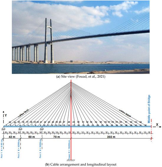
Figure 1.
Suez Canal cable-stayed Bridge [21].
The stay cable system consists of 128 cables arranged in a double-plane, semi-fan configuration, with a spacing of approximately 10 to 12 m along the deck (see Figure 1b). The cables are grouped according to their positions, with cross-sectional areas ranging from 67.06 cm2 for the largest cables near mid-span to 27.51 cm2 for the smallest cables near the side spans. This arrangement optimizes force distribution while maintaining an efficient and aesthetically pleasing geometry.
2.1. Steel Box Girder System
The deck system in the original design is a single steel box girder with a total width of 20.8 m, which accommodates four lanes of vehicular traffic along with shoulders (see Figure 2a) [23]. The depth of the box girder varies from 1.2 m at the edges to 2.6 m at mid-span, optimizing the section for weight reduction and stiffness. The top and bottom deck plates are constructed from orthotropic steel plates with closed ribs, 16 mm thick for the top plate and 11 mm thick for the bottom plate, providing excellent fatigue performance and high bending capacity. To maintain the integrity of the box section, 10 mm-thick cross diaphragms are installed at cable anchor points and at midpoints between them.
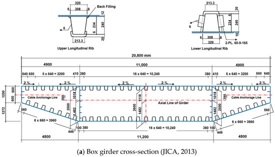
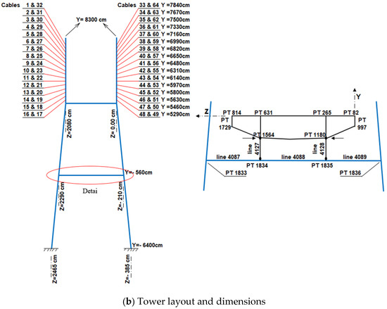
Figure 2.
Details of the current design (steel box girder system) [23].
Two massive H-shaped reinforced concrete pylons (Figure 2b), each rising approximately 155 m above the foundations, support the main span. The pylons are designed as hollow box sections with variable dimensions, ranging from 760 × 780 cm at the base with 70 cm wall thickness to 250 × 500 cm near the top with 50 cm wall thickness. These pylons anchor the stay cables and provide lateral stability to the entire bridge system.
The bridge was designed in accordance with the Egyptian Code of Practice, accounting for heavy highway traffic loads, wind loads of up to 250 kg/m2 in the absence of live loads (and 150 kg/m2 when live loads are present), and temperature variations of ±30 °C relative to a reference temperature of 20 °C. The robust design of the Suez Canal Bridge makes it an ideal case study for comparative evaluation, as its detailed data and well-documented performance allow the development of an accurate finite element model. This model serves as the baseline for comparing the structural response of the conventional steel box girder deck to the proposed composite space truss deck system in the present research.
2.2. Composite Space Truss System
The proposed deck system consists of a composite space truss structure designed to replace the conventional steel box girder in cable-stayed bridge applications. The system is formed from a series of repeated square-on-square pyramid units, each with a 3 m × 3 m base and a height of 3 m, creating a highly efficient three-dimensional structural framework (see Figure 3a). This space truss acts compositely with a 25 cm hollow reinforced concrete slab, which serves as the riding surface and contributes significantly to the global stiffness of the deck (see Figure 3b). Full interaction between the concrete slab and the top chord members of the truss is assumed, ensuring effective composite action and minimizing differential slip under service loads.
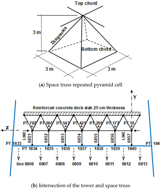
Figure 3.
Details of the proposed system (composite space truss system).
To optimize the structural performance, the members of the space truss are grouped based on their internal forces and assigned different cross-sectional areas. The members are classified into heavy and light groups, with the heavier sections provided for the perimeter bays, the transverse bays at the cable planes, and the regions surrounding the pylons and piers, ensuring adequate stiffness and stability of the system. The cross-sectional areas of the space truss members indicate a logical hierarchy based on the internal force demands of the space truss system. The bottom chord members have the largest areas, with the heavy group reaching 111 cm2 and the light group 42 cm2. This difference, about 2.6 times, reflects the higher tensile forces typically developed in the lower chord, especially at midspan and near the pylons, where the section is further increased to 184 cm2 to accommodate maximum axial tension. The top chord members, which primarily resist compression and benefit from the composite action with the 25 cm hollow reinforced concrete slab, are designed with smaller cross sections of 36 cm2 for the heavy members and 22.56 cm2 for the light ones. The diagonal members fall between the two, having 56 cm2 for the heavy and 22.56 cm2 for the light group, with the same section used for the light top chord and diagonals to simplify fabrication and connections. This distribution of member sizes, bottom chord > diagonals > top chord, demonstrates an efficient design strategy that aligns with the expected axial force patterns within the truss system.
The cable arrangement, cable cross-sectional areas, and pylon dimensions remain identical to those of the original Suez Canal Bridge design, allowing for a direct comparison between the conventional box girder deck and the proposed composite space truss deck under identical loading and boundary conditions. The composite space truss system is intended to provide a lighter, stiffer, and more economical alternative, reducing steel consumption significantly while maintaining the required strength, serviceability, and durability criteria for long-span cable-stayed bridges.
3. Finite Element Analysis
3.1. Modeling Approach
A comprehensive three-dimensional finite element (FE) analysis was conducted to evaluate and compare the structural performance of the conventional steel box girder system and the proposed composite space truss system for cable-stayed bridges. The modeling and simulation were carried out using the COSMOS/M (version 2.7) finite element package [24]. Due to the geometric and loading symmetry of the bridge, only one-half of the entire structure was modeled, thereby optimizing computational efficiency without compromising accuracy. Both bridge systems were modeled considering the interaction among the deck, cables, pylons, and anchorages, ensuring that the global load-transfer mechanism was accurately represented. The models incorporated the effects of dead, live, wind, and temperature loads, as well as geometric nonlinearity due to large deformations.
3.2. Element Types and Material Properties
3.2.1. Box Girder System
The steel box girder was modeled using four-node shell elements (Shell 4), each possessing four translational and three rotational degrees of freedom per node. These elements were selected for their ability to capture bending, membrane, and shear deformations in thin-walled structures. The top and bottom flanges of the box girder, which are fabricated from orthotropic steel plates with closed ribs, were represented by equivalent isotropic shell sections having the same bending stiffness and self-weight as the original orthotropic configuration. The web plates and diaphragms were modeled as planar shell elements with appropriate thicknesses as per the bridge’s design drawings. The reinforced concrete pylons were modeled using 3D beam elements, with a characteristic concrete compressive strength of fcu = 50 MPa. Stay cables were idealized as 3D truss elements capable of carrying tension only. The cables had an ultimate tensile strength of fu = 1800 MPa, and were allowed to sustain stresses up to 43% of fu to simulate service-level conditions. Compression was not permitted in any cable element.
3.2.2. Composite Space Truss System
The composite space truss deck was modeled as a hybrid structure consisting of steel truss members and a reinforced concrete slab acting compositely through full interaction at the top chord joints. All top, bottom, and diagonal members of the truss were represented by 3D truss elements. The top concrete slab, which is a 250 mm thick hollow slab, was modeled using Shell 4 elements with an equivalent thickness of 247 mm to maintain the same moment of inertia and self-weight as the actual voided configuration. The concrete material was modeled as reinforced concrete with fcu = 50 MPa. Cables and pylons were modeled identically to the box girder system, ensuring consistent boundary and load-transfer conditions across both models. Full composite action was assumed between the top chord members and the concrete slab, achieved by rigid connection constraints at shared nodes.
3.2.3. Mesh Discretization and Material Properties
A detailed finite element discretization was adopted to ensure accurate representation of the global structural response. The deck systems were modeled using appropriate element types, with shell elements employed for the box girder and concrete slab, truss elements for the stay cables and space truss members, and beam elements for the pylons. A refined mesh was applied in regions of high stress gradients, particularly near the cable anchorage zones, pylon–deck connections, and mid-span regions, while a relatively coarser mesh was used in less critical regions to optimize computational efficiency. The total number of elements and nodes was selected to achieve a balance between accuracy and computational cost.
A mesh sensitivity study was conducted by refining the mesh density along the deck and cable elements. The results indicated that further mesh refinement produced negligible changes (less than 2%) in key response parameters such as mid-span deflection and cable forces, confirming the adequacy and convergence of the adopted mesh.
The material properties used in the analysis were defined based on typical values for structural steel and reinforced concrete. The steel components (box girder, truss members, and cables) were assigned an elastic modulus of 200 GPa and a unit weight of 78.5 kN/m3. The reinforced concrete slab and pylons were modeled with a compressive strength of 50 MPa, an elastic modulus of 30 GPa, and a unit weight of 25 kN/m3. The stay cables were modeled as tension-only elements with an ultimate tensile strength of 1800 MPa. All materials were assumed to behave linearly elastic within the service load range.
3.3. Nonlinear Analysis Formulation
Given that geometric nonlinearity predominates in long-span cable-stayed bridges, a nonlinear large-displacement analysis was conducted using the Newton–Raphson iterative scheme. Material nonlinearity was neglected since all materials were assumed to behave elastically within service load levels. The catenary effect of the stay cables, arising from the interaction between axial tension and self-weight, was incorporated through an equivalent secant modulus of elasticity (Eeq), which accounts for both geometric and material stiffness variations over each load increment, as shown in the Ernst formula for sag-induced cable stiffness reduction (Equation (1)) [25]:
where W is the unit weight of cable, L is the cable length, E is the material elastic modulus, A is the cross-sectional area, and Ti and Tf are the initial and final cable tensions over a load increment, respectively.
The Ernst equivalent modulus formulation was adopted, which incorporates sag-induced stiffness reduction without explicitly modeling full catenary behavior. This approach is widely used in the analysis of cable-stayed bridges under service load conditions, where geometric nonlinearity due to cable sag governs the response, while material nonlinearity remains negligible. The formulation provides an efficient balance between computational cost and accuracy for global structural analysis and comparative studies.
The Ernst model assumes relatively small geometric changes and uniform tension along the cable, which may limit its accuracy under large displacements, significant tension variation, or extreme loading scenarios. More refined approaches, such as nonlinear catenary cable elements or iterative tension-updating schemes, can better capture these effects, particularly in construction-stage or dynamic analyses [26,27]. Nevertheless, for the present study focusing on global bridge behavior under service loads, the Ernst formulation is considered appropriate and sufficiently accurate.
An auto-incremental loading scheme was implemented with a starting increment of 10% of the total applied load and a maximum step size of 40%. The tangent stiffness matrix was updated and decomposed at the beginning of each step and remained constant during each iteration cycle, ensuring stable and efficient convergence.
3.4. Boundary Conditions
The deck–pylon junction was modeled as a semi-rigid connection that permits limited rotation but restrains translation, replicating actual field conditions. The anchorages at the abutments were fully fixed in all directions.
3.5. Load Applications
A comprehensive set of static and environmental load cases was considered in the finite element simulations to evaluate the global and local responses of both the steel box girder and the composite space truss cable-stayed bridge systems. All load magnitudes and combinations were defined in accordance with the ECP-201 [28]. The main load categories included dead load, superimposed dead load, live load, wind load, and thermal (temperature) load. Each category is detailed below.
3.5.1. Dead Load
The dead load (self-weight) was automatically computed in the finite element models based on the material densities and the geometric properties of the structural elements. For the box girder system, the dead load was derived from the modeled shell elements representing the top and bottom orthotropic steel plates, diaphragms, and webs. Equivalent shell sections were assigned thicknesses such that the self-weight accurately matched the original design configuration. For the composite space truss system, the self-weight was obtained directly from the member cross-sectional properties and the unit weight of the materials (steel for truss members and reinforced concrete for the deck slab). The computed average self-weight intensities were 4.7 kN/m2 and 6.2 kN/m2 for the box girder system and composite space truss system, respectively. The higher self-weight of the composite space truss is primarily attributed to the inclusion of the reinforced concrete deck slab and the more complex truss geometry. Despite this, the system still offers considerable material economy in terms of steel consumption, as only one-third of its total mass is composed of steel.
3.5.2. Superimposed Dead Load
In addition to the self-weight, superimposed dead loads were applied to account for the pavement layer, handrails, sidewalks, utilities, and other non-structural components.
A uniformly distributed load of 1.96 kN/m2 was adopted to represent these additional permanent loads. This value corresponds to a pavement layer of approximately 8 cm thickness, together with the average weight of the sidewalks and ancillary attachments. The superimposed dead load was applied uniformly across the bridge deck surface to both systems to ensure consistency in comparative analysis.
3.5.3. Live Load
The live load was simulated to represent vehicular and pedestrian traffic in accordance with the ECP-201 [28], which prescribes concentrated and distributed load models for multi-lane highway bridges. To facilitate numerical comparison between the two structural systems, the live load was converted into an equivalent uniformly distributed load of 3.55 kN/m2, representing the combined effects of truck loads, lane loads, and sidewalk loads. This equivalent uniform load was calculated based on the following representative configuration: (1) A 60-ton heavy truck positioned in the main lane, with an additional distributed load of 4.9 kN/m2 acting in front and behind the truck; (2) A 30-ton auxiliary truck positioned in the adjacent lane, combined with a distributed load of 2.9 kN/m2 over the remaining lanes and sidewalks; and (3) Dynamic impact effects were incorporated in the principal lane only, consistent with code specifications. This idealization allows for direct and consistent comparison of the bridge response under operational service conditions while maintaining computational efficiency.
3.5.4. Wind Load
Wind loading was considered as a static pressure acting horizontally on the bridge deck and superstructure. Two cases were examined in accordance with the Egyptian Code: wind acting concurrently with live load of 1.5 kN/m2 and wind acting in the absence of live load of 2.5 kN/m2. These pressures were applied over the projected area of the bridge deck and pylons to simulate the most unfavorable lateral loading conditions. The wind loads were distributed proportionally to the exposed areas of the box girder and the space truss system, with the latter exhibiting a more open geometry and therefore a smaller effective wind resistance factor. The influence of wind load was particularly important in evaluating lateral sway, torsional response, and pylon deformation, as discussed in the subsequent analysis section.
3.5.5. Temperature (Thermal) Load
Thermal effects were modeled as uniform temperature variations applied to all structural elements of the bridge. The reference temperature was taken as 20 °C, and temperature variations of ±30 °C were imposed to evaluate the bridge’s response under extreme climatic conditions. The thermal load was simulated by defining a linear temperature change across the structural elements, resulting in differential thermal strains in the deck, cables, and pylons. This loading condition is critical for assessing the vertical deflection of the deck due to expansion or contraction, pylon sway and rotation, and redistribution of axial forces within the stay cables.
The thermal analysis results indicated that the composite space truss system exhibited higher temperature sensitivity compared to the box girder deck, mainly because of the greater number of flexible connections within the truss framework. The temperature-induced deflection reached approximately 25.3% of the live-load deflection in the composite space truss system, compared to 15.1% for the box girder system.
3.6. Comparative Uniform Loading for Stiffness Evaluation
To ensure consistency between models, both systems were analyzed under identical load combinations and boundary conditions. The post-tensioning forces in the stay cables were maintained at comparable levels (maximum of 300 tons per cable for the truss system versus 265 tons for the box girder), ensuring an unbiased comparison of structural performance (see Figure 4). This level of post-tensioning was confirmed by the reported cable tensile force of 292.9 tons, as documented in [23]. Due to differences in self-weight of the two systems, preliminary verifications were performed by analyzing both systems under a uniform load of 1.0 kN/m2, neglecting self-weight and pre-tensioning, to assess their relative stiffness.
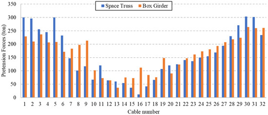
Figure 4.
Pretension forces in cables.
Figure 5 compares the vertical deflection profiles of the steel box girder and composite space truss deck systems subjected to a uniformly distributed load of 1.0 kN/m2 along the bridge span. All reported deflection profiles correspond to the vertical deflection along the longitudinal centerline of the bridge deck (mid-width line). This reference line was selected to represent the global structural response and to ensure consistent comparison between the two deck systems. The results demonstrate that both systems exhibit nearly identical global stiffness characteristics, as indicated by the close proximity of their deflection curves throughout the entire span length.
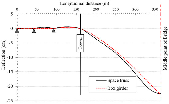
Figure 5.
Deflections of the box girder versus composite space truss systems due to uniform load = 1.0 kN/m2.
The maximum mid-span deflections are approximately 22.5 cm for the composite space truss system and 22.9 cm for the box girder deck, confirming that the two structural configurations possess comparable elastic stiffness under uniform loading. This validates the finite-element modeling accuracy and indicates that substituting the traditional steel box girder with the proposed space truss composite system would not compromise serviceability or stiffness performance. The slightly smaller deflection of the space truss deck highlights the beneficial contribution of the composite concrete slab and the three-dimensional truss configuration, which provide efficient load distribution and enhanced bending resistance. Moreover, the consistency of the deflection profiles across the tower and side-span regions suggests uniform stress transfer between the cable-stay system and the deck structure.
The comparative uniform-load analysis confirms that the composite space truss system achieves equivalent stiffness and deflection control as the conventional box girder while offering potential advantages in material efficiency and construction simplicity.
4. Results and Discussion
Linear and nonlinear analyses are carried out on both box girder and space truss systems. The effect of nonlinearity on bridge deflection and stiffness is studied. Also, the effect of the space truss depth on the stiffness and deflection is reported, as well as the type of concrete deck (normal and lightweight concrete).
4.1. Linear Analysis
To determine the camber requirements for both systems, the conventional steel box girder and the proposed composite space truss girder, the structures were first analyzed under dead load only to obtain their corresponding elastic deflection profiles. These camber values represent the upward pre-deformation necessary to achieve a zero-deflection configuration under service dead loads and post-tensioning effects.
Figure 6 illustrates the longitudinal deflection profiles of the steel box girder and composite space truss bridge systems subjected to dead load only. The figure shows that the composite space truss experiences a noticeably higher mid-span deflection—approximately 38.9 cm, compared to 31.4 cm for the box girder. Due to the limited availability of field monitoring data for the Suez Canal Bridge, direct validation was not feasible; however, the predicted mid-span deflection under dead load (31.4 cm) compares well with the reported value of approximately 35.9 cm [23], supporting the accuracy of the developed finite element model. This difference is primarily attributed to the greater self-weight of the composite space truss system due to the inclusion of the concrete slab, which increases the dead-load demand on the structure. Although the composite space truss system reduces steel consumption, the inclusion of the reinforced concrete slab results in a higher overall self-weight (6.2 kN/m2 compared to 4.7 kN/m2). This increase contributes to the larger deflection observed under dead load. However, under uniform and live loading conditions, both systems exhibit comparable stiffness, indicating that the proposed system maintains overall structural efficiency despite the higher mass.
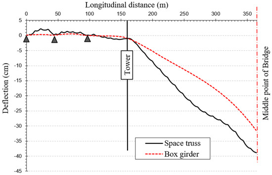
Figure 6.
Deflection of the box girder versus composite space truss systems due to dead load.
The steel box girder, being lighter and more compact, demonstrates slightly better stiffness performance under its own weight. However, despite the higher deflection, the deflected shape of the space truss remains smooth and consistent along the span, indicating adequate stiffness distribution and proper load transfer through the truss members and cable system. This response confirms that the composite space truss exhibits stable elastic behavior and that its performance under self-weight remains within acceptable serviceability limits. These results highlight the importance of considering self-weight effects when designing composite truss decks and suggest that camber adjustments may be required to achieve a zero-deflection configuration under dead load and post-tensioning forces.
Figure 7 compares the longitudinal deflection responses of the composite space truss and steel box girder bridge decks under live load conditions. The results reveal that the composite space truss system exhibits a slightly smaller mid-span deflection of approximately 81.6 cm, compared to 83.1 cm for the box girder. This reduction in deflection demonstrates the higher overall stiffness and structural efficiency of the composite space truss deck. The improvement is primarily due to the three-dimensional load distribution within the truss configuration and the composite interaction between the reinforced concrete slab and the steel top chord members, which enhances flexural resistance.
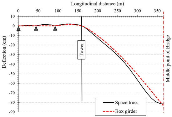
Figure 7.
Deflection of the box girder versus composite space truss systems due to live load.
Both systems display similar deformation profiles along the bridge span, indicating consistent load-sharing behavior between the deck and stay cables. The results confirm that, despite its lighter steel content, the composite space truss maintains or slightly exceeds the stiffness performance of the conventional steel box girder under service live loads, validating its potential as a viable and economical alternative for long-span cable-stayed bridges.
The torsional rigidity of the proposed bridge systems was evaluated under unsymmetrical loading conditions, where only half of the bridge width was subjected to live load. Figure 8 presents the vertical deflection profiles along the longitudinal direction of both bridge types, comparing the deflection of the two top edges. For the box girder deck, a noticeable difference in vertical displacement is observed between the loaded and unloaded edges, reaching approximately 5.26 cm at midspan. In contrast, the space truss system exhibits a smaller difference of about 4.93 cm between the two edges. This reduction in differential deflection demonstrates the higher torsional rigidity and improved resistance to twisting of the composite space truss system compared to the conventional box girder configuration.
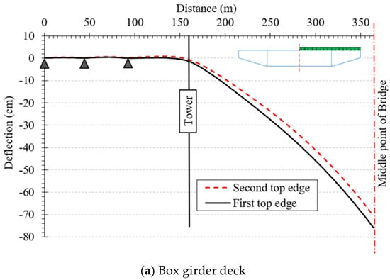
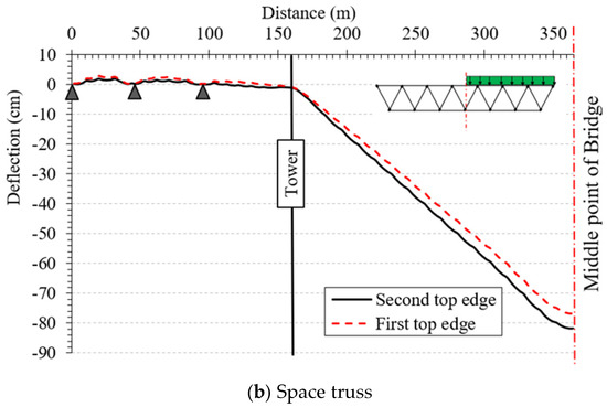
Figure 8.
The vertical deflection profiles along the longitudinal direction of both bridge types under unsymmetrical loading conditions.
The lateral sway responses of the two bridge systems under wind loading are presented in Figure 9. As illustrated, the box girder deck demonstrates noticeably smaller lateral displacements along the bridge span compared to the composite space truss system, indicating its higher lateral rigidity. The maximum lateral sway at midspan reaches approximately 2.1 cm for the box girder, while the space truss exhibits a significantly higher value of about 5.4 cm. This behavior highlights the relatively lower lateral stiffness of the space truss configuration. However, the lateral stability of the composite space truss can be markedly enhanced by enclosing its sides and bottom with non-metallic sheets, which would effectively increase its torsional and lateral rigidity under wind effects.
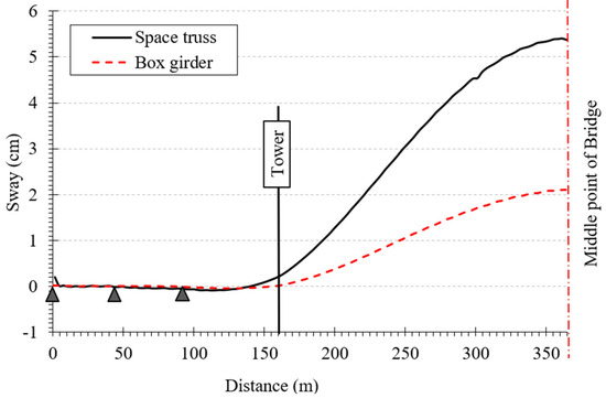
Figure 9.
Side sway for both systems under dead, live, and wind loads.
It should be noted that the initial cable tensioning state is maintained at comparable levels in both models, as confirmed by the close agreement in post-tensioning forces presented in Figure 4. Therefore, the observed differences in lateral response are not attributed to variations in cable force distribution. The increased lateral displacement of the composite space truss system is primarily associated with its lower inherent lateral stiffness, resulting from its open three-dimensional configuration and reduced sectional continuity compared to the closed box girder. In addition, the global interaction between the deck, stay cables, and pylons influences the lateral response, as the space truss system provides a different stiffness distribution and load-transfer mechanism under wind loading. While the open configuration contributes to reduced aerodynamic resistance, it also leads to lower resistance to lateral deformation. It is noted that the lateral stiffness of the space truss system could be enhanced through design modifications such as partial enclosure or additional bracing; however, these measures are presented here as potential improvements rather than primary explanations of the observed behavior.
4.2. Nonlinear Analysis
Under the effect of live load (LL) only, both the space truss and box girder bridge systems display similar deformation trends along the bridge length, with minor deflections in the back span and significant sag in the main span beyond the tower (see Figure 10a). The space truss system exhibits slightly lower deflection values at midspan, approximately 75–80 cm downward, compared to 80–85 cm for the box girder, indicating marginally higher stiffness for the space truss under live loading alone. This behavior demonstrates that both systems perform comparably under service loads, but the space truss maintains a slightly better resistance to vertical deformation due to its efficient truss action in distributing loads.
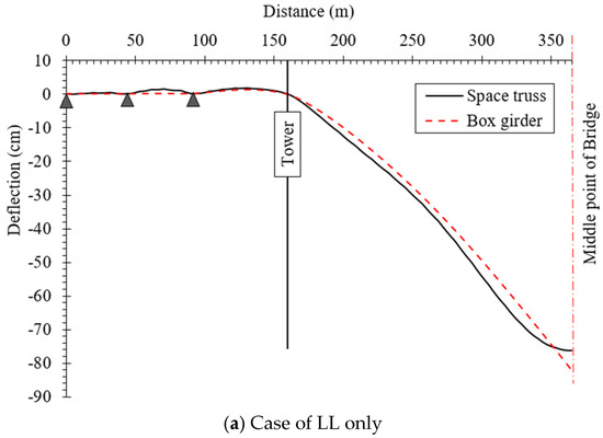
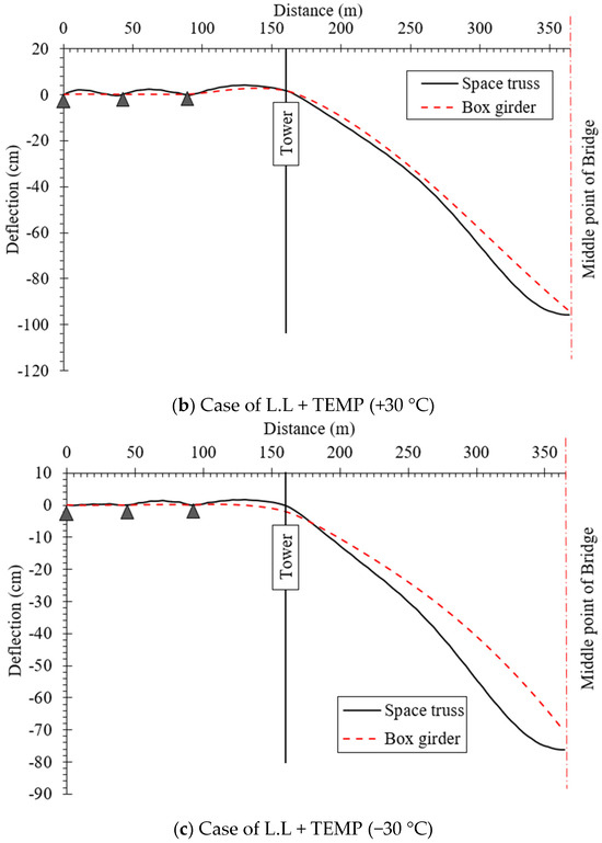
Figure 10.
Longitudinal deflection comparisons due to live loads with temperature variances.
When temperature rise is introduced (LL + TEMP +30 °C), both systems experience increased downward deflection across the main span as a result of thermal expansion (see Figure 10b). The space truss deflects by roughly 100–105 cm, whereas the box girder reaches about 95–100 cm. This significant increase in deflection highlights the influence of thermal softening and reduced axial stiffness. The space truss is more affected by temperature increase, suggesting that its open-web configuration and multi-element connectivity make it more sensitive to temperature-induced elongation and internal stress redistribution. Consequently, thermal expansion reduces the effectiveness of its load path and leads to a greater overall sag compared to the box girder.
Conversely, under a temperature drop (LL + TEMP −30 °C), the two systems respond differently. The box girder exhibits an increase in stiffness, with its midspan deflection reducing to approximately 70–75 cm—slightly less than under LL only—indicating that thermal contraction enhances its compression and axial stiffness (see Figure 10c). In contrast, the space truss shows a small increase in deflection (around 85 cm), which may be attributed to differential thermal strains between the top and bottom chords or between materials in composite components. These secondary thermal stresses could lead to localized bending and minor increases in sag, offsetting the beneficial effects of temperature contraction.
The space truss system demonstrates greater sensitivity to temperature fluctuations, with both heating and cooling causing larger deviations from the baseline deflection compared to the box girder. The higher thermal sensitivity of the composite space truss system is mainly attributed to its open configuration, composite steel–concrete interaction, and temperature-induced redistribution of cable forces. This behavior implies that the space truss may require more detailed thermal design considerations, such as flexible connections, expansion joints, or additional thermal insulation, to mitigate deformation effects. From a serviceability perspective, high-temperature conditions represent the most critical loading scenario for both systems, particularly for the space truss, as deflection limits could be approached or exceeded under combined live load and thermal expansion.
Under the live load (LL) condition only, the tower sway profiles for both bridge systems exhibit similar curvatures, with the maximum sway occurring at the tower top (see Figure 11). The box girder system shows a slightly greater top deflection of about 17.8 cm, compared to 17.0 cm for the space truss system, indicating that the space truss provides slightly higher lateral stiffness at the tower. At deck level (around 63 m height), the sway values are approximately 4.8 cm for the space truss and 5.3 cm for the box girder, again showing about 10% higher lateral displacement for the box girder due to its relatively higher global flexibility and the greater horizontal force component transmitted from the deck (Figure 11a).
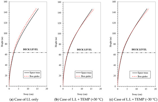
Figure 11.
Tower Sway Diagram.
When the temperature rises by +30 °C, both systems experience small increases in sway due to thermal expansion and redistribution of internal forces within the deck and stay system (Figure 11b). The top sway of the space truss tower increases to around 17.2 cm, while that of the box girder slightly decreases to 17.3 cm, making the difference between the two negligible (less than 1%). At deck level, the sway of both systems rises to approximately 5.6 cm, corresponding to an increase of about 17% for the space truss and 6% for the box girder compared to the LL-only case. This suggests that the space truss system is more sensitive to temperature-induced expansion, likely because of its open configuration and multiple member connections that amplify the effects of differential elongation.
In contrast, under a temperature drop of −30 °C, the pylon sway responses show opposite trends (Figure 11c). The box girder system becomes slightly stiffer, with the top sway decreasing to approximately 16.8 cm, whereas the space truss sway increases marginally to about 17.6 cm, representing a 3–5% difference between the two systems. At deck level, the space truss exhibits 4.6 cm sway (a 4% reduction relative to LL only), while the box girder drops to 4.3 cm (about 19% reduction), showing that cooling enhances stiffness more effectively in the box girder system.
The quantitative results indicate that temperature variations have only a modest influence on tower sway—generally less than 10% at the top—but can cause up to 20% variation near the deck level. The box girder tower tends to stiffen more under cooling, while the space truss tower shows slightly greater sensitivity to thermal expansion under heating. These results confirm that both systems maintain excellent lateral stability under temperature effects, with only minor thermal influence on the tower’s overall serviceability performance.
4.3. Effect of Space Truss Depth
The results shown in Figure 12 clearly demonstrate the significant influence of the space truss depth on the overall stiffness and deflection behavior of the composite cable-stayed bridge system. The longitudinal deflection curves for truss depths of 2.5 m, 3.0 m, 3.5 m, and 4.0 m reveal that increasing the truss depth consistently enhances the global stiffness and reduces the maximum mid-span deflection of the bridge.
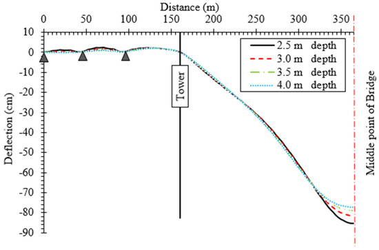
Figure 12.
Effect of Composite Truss Depth on Cable-Stayed Bridge Stiffness.
For the smallest truss depth of 2.5 m, the deflection at mid-span reaches approximately −86 cm, representing the lowest stiffness configuration among the four cases. Increasing the depth to 3.0 m yields a noticeable improvement, reducing the mid-span deflection to around −82 cm (about a 5% decrease). Further deepening the truss to 3.5 m results in an additional reduction in deflection to nearly −78 cm, corresponding to roughly a 10% increase in global stiffness relative to the 2.5 m case. The stiffest configuration, with a 4.0 m truss depth, produces the smallest deflection, approximately −74 cm, indicating an overall improvement in vertical stiffness of about 15% compared with the shallowest truss.
The improvement in performance with increasing depth can be attributed to the greater moment of inertia and enhanced geometric efficiency of the deeper truss section, which increases its flexural rigidity and load-carrying capacity. A larger truss depth also improves the lever arm between the upper and lower chords, leading to smaller member forces and reduced overall deformation. This effect becomes more pronounced in the main span beyond the tower, where bending moments are dominant. The shapes of the deflection curves confirm that all cases follow the same deformation profile, with differences mainly in the amplitude rather than in the pattern of deformation, indicating that changing the truss depth alters stiffness but not the fundamental load-transfer mechanism.
It is also noteworthy that the rate of improvement in stiffness decreases as depth increases. While increasing the depth from 2.5 m to 3.0 m provides a substantial reduction in deflection, further increments beyond 3.5 m offer diminishing returns. This suggests that beyond a certain threshold, additional depth contributes marginally to overall stiffness relative to the associated increase in material and fabrication costs.
4.4. Effect of Concrete Type
The results presented in Figure 13 illustrate the influence of concrete type on the longitudinal deflection of the cable-stayed bridge incorporating a composite space truss deck. Two types of concrete were evaluated: lightweight concrete and ordinary (normal-weight) concrete. The comparison of their deflection profiles under identical loading conditions reveals that the type and density of concrete play a substantial role in the bridge’s overall stiffness and deformation characteristics.
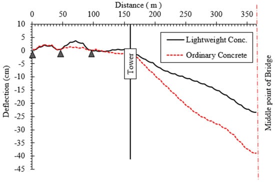
Figure 13.
Longitudinal deflection of bridge (composite space truss deck) for light-weight & ordinary concrete.
The deflection curves show that the bridge constructed with lightweight concrete exhibits noticeably smaller deflections throughout its span compared to the bridge using ordinary concrete. At mid-span, the maximum downward deflection for the lightweight concrete case is approximately −28 cm, while that for the ordinary concrete system reaches about −40 cm, representing a reduction of nearly 30% in mid-span deflection when lightweight concrete is employed. This considerable improvement indicates that the reduction in dead load—resulting from the lower density of lightweight concrete—significantly decreases the overall bending demand on both the deck and the stay-cable system.
In the back span region (from 0 to 150 m), both systems show relatively minor deflections with negligible differences, as this region is primarily influenced by cable restraint and tower stiffness rather than self-weight effects. Beyond the tower, however, the distinction between the two curves becomes more pronounced. The ordinary concrete deck exhibits a steeper downward slope, indicating larger bending and axial deformations in the main span. This behavior underscores the fact that self-weight is a critical factor in long-span bridge performance, especially for cable-stayed configurations where the main span is largely supported by stay cables that are sensitive to axial load variations.
Using lightweight concrete reduces the total dead load, allowing the cable system to maintain a more efficient stress distribution and smaller elongations under service loads. The result is a noticeable enhancement in global stiffness and reduced vertical deformation. Moreover, lightweight concrete contributes to reduced pylon and foundation forces, leading to potential material savings and extended service life due to lower stress cycles. However, this advantage should be balanced against the typically lower compressive strength and modulus of elasticity of lightweight concrete, which may influence local deck performance if not properly compensated by design.
5. Conclusions
This study introduced and evaluated an innovative composite space truss deck system as a practical and economical alternative to the conventional steel box girder in cable-stayed bridges, using the Suez Canal Bridge as a detailed case study. Through extensive linear and nonlinear finite element analyses under dead, live, wind, and temperature loads, the comparative assessment revealed significant insights into the structural performance, stiffness characteristics, and thermal sensitivity of both systems. The key findings of this study can be summarized as follows:
- The proposed composite space truss deck achieved a 5–7% reduction in mid-span deflection under live loads relative to the steel box girder, demonstrating superior vertical stiffness. Under unsymmetrical loading, the space truss system exhibited a smaller differential edge deflection (4.93 cm vs. 5.26 cm), confirming its higher torsional rigidity and improved three-dimensional load distribution efficiency.
- Geometric nonlinearity had a limited influence on global response, increasing mid-span deflection by only 6.56% in the space truss and 1.64% in the box girder system. However, the space truss exhibited greater sensitivity to temperature fluctuations, with a 25.3% change in mid-span deflection for ±30 °C variation compared to 15.1% for the box girder. This emphasizes the need for careful thermal design detailing—such as expansion joints and flexible connections—when implementing open-web truss systems.
- Both systems maintained excellent global stability. The pylon sway under live loading was nearly identical, differing by less than 5%, with the space truss providing slightly higher stiffness near the deck level. While the box girder showed better lateral rigidity under wind loading, the space truss’s lateral stiffness could be enhanced through lightweight non-metallic enclosures, improving aerodynamic and torsional stability.
- Increasing the space truss depth from 2.5 m to 4.0 m reduced mid-span deflection by approximately 15%, confirming that deck depth significantly influences stiffness, though the rate of improvement diminishes beyond 3.5 m. Moreover, replacing normal-weight concrete with lightweight concrete reduced mid-span deflection by nearly 30%, demonstrating the potential for further material optimization without compromising structural performance.
- The composite space truss deck achieved substantial material and cost savings, requiring nearly two-thirds less steel than the box girder while maintaining a comparable self-weight of about 490 kg/m2. The integration of a reinforced or lightweight concrete slab provides an excellent balance between stiffness, durability, and constructability.
- The higher thermal sensitivity of the composite space truss system is mainly attributed to its open configuration, composite steel–concrete interaction, and temperature-induced redistribution of cable forces. This behavior may be mitigated through design measures such as expansion joints, flexible connections, and optimized truss stiffness.
Further refinement of the numerical modeling approach is recommended, including the incorporation of advanced cable formulations, material nonlinearities, and time-dependent effects such as creep and shrinkage of concrete. In addition, extending the analysis to other bridge configurations, span arrangements, and loading scenarios, such as seismic, fatigue, and dynamic wind effects, would provide a more comprehensive understanding of the system’s behavior. Investigation of construction-stage analysis and long-term performance is also essential to fully assess the practical applicability of the proposed system in modern bridge engineering in terms of connection detailing, fabrication tolerances, and erection sequence.
Author Contributions
Conceptualization, H.F.S. and M.A.; formal analysis, A.E.-Z.; methodology, A.E.-Z. and M.A.; software, A.E.-Z.; supervision, H.F.S. and M.A.; validation, A.E.-Z.; visualization, H.F.S. and M.A.; writing—original draft, H.F.S. and M.A.; writing—review and editing, A.E.-Z. All authors have read and agreed to the published version of the manuscript.
Funding
This research received no external funding.
Data Availability Statement
The data presented in this study are available upon request from the corresponding author.
Conflicts of Interest
The authors declare no conflicts of interest.
References
- Bannazadeh, B.; Zomorodian, Z.S.; Maghareh, M.R. A Study on Cable-Stayed Bridges. Appl. Mech. Mater. 2012, 193–194, 1113–1118. [Google Scholar] [CrossRef]
- Chai, S.; Huang, K.; Wang, X. Influence of Crossing Cable Arrangement on the Static Performance of Long-Span Three-Tower Cable-Stayed Bridges. Appl. Sci. 2025, 15, 6355. [Google Scholar] [CrossRef]
- Pedro, J.J.O.; Reis, A.J. Composite cable-stayed bridges: State of the art. Proc. Inst. Civ. Eng.-Bridge Eng. 2016, 169, 13–38. [Google Scholar] [CrossRef]
- Lin, W.; Yoda, T. (Eds.) Chapter Ten—Cable-Stayed Bridges. In Bridge Engineering; Butterworth-Heinemann: Oxford, UK, 2017; pp. 175–194. [Google Scholar] [CrossRef]
- De Miranda, M. Chapter 15—Long-span bridges. In Innovative Bridge Design Handbook; Pipinato, A., Ed.; Butterworth-Heinemann: Oxford, UK, 2016; pp. 383–425. [Google Scholar] [CrossRef]
- He, X.; Wang, Z.; Li, C.; Gao, C.; Liu, Y.; Li, C.; Liu, B. Experimental Test and Finite Element Analysis on a Concrete Box Girder of a Cable-Stayed Bridge with W-Shaped Prestressed Concrete Diagonal Braces. Buildings 2024, 14, 506. [Google Scholar] [CrossRef]
- Zheng, Y.; Wang, J.; Guo, P.; Zhang, Y. A Review of the Mechanical Properties of and Long-Term Behavior Research on Box Girder Bridges with Corrugated Steel Webs. Buildings 2024, 14, 3056. [Google Scholar] [CrossRef]
- Terreros-Bedoya, A.; Negrin, I.; Payá-Zaforteza, I.; Yepes, V. Hybrid steel girders: Review, advantages and new horizons in research and applications. J. Constr. Steel Res. 2023, 207, 107976. [Google Scholar] [CrossRef]
- El-Sheikh, A. Development of a new space truss system. J. Constr. Steel Res. 1996, 37, 205–227. [Google Scholar] [CrossRef]
- Zhu, J.; Zhang, Y.; Zhou, S.; Rong, W. Thermal effect analysis of a steel truss cable-stayed bridge with two-layer decks under sunlight. Adv. Struct. Eng. 2023, 27, 119–133. [Google Scholar] [CrossRef]
- Byun, N.; Lee, J.; Won, J.-Y.; Kang, Y.-J. Structural Responses Estimation of Cable-Stayed Bridge from Limited Number of Multi-Response Data. Sensors 2022, 22, 3745. [Google Scholar] [CrossRef] [PubMed]
- Labib, S.; Bakhoum, M.M. General Aspects of Suez Canal Bridges, A Bridge for Peace and Prosperity in the Middle East. Egyptian Society of Engineers. In Proceedings of the Bridge Engineering Conference, Sharm ElSheikh, Egypt, 26–30 March 2000; Volume 2, pp. 651–668. [Google Scholar]
- Sharaf, M.; Ishitate, N.; Ishii, T. Construction of Suez Canal Bridge (Central Portion). Egyptian Society of Engineers. In Proceedings of the Bridge Engineering Conference, Sharm El-Sheikh, Egypt, 26–30 March 2000; Volume 2, pp. 629–640. [Google Scholar]
- Makowski, Z.S. Space Structures In Mexico: A Review of Their Recent Developments. Build. Specif. 1981, 10, 21–25. [Google Scholar]
- Makowski, Z.S. Space Structures of Today and Tomorrow. In Third International Conference on Space Structures; CRC Press: Surrey, UK, 1984; pp. 1–8. [Google Scholar]
- Castilio, H. A Space Frame Construction with Steel and Reinforced Concretethe ‘Tridilosa’ Spatial Structures. In Space Structures; Davis, R.M., Ed.; Blackwell Scientific Publisher: Oxford, UK, 1967; pp. 1089–1093. [Google Scholar]
- Srivastava, N.K.; Sherbourne, A.N.; Roorda, J.; Canadian Society for Civil Engineering and International Association for Shell and Spatial Structures. Innovative Large Span Structures: IASS-CSCE International Conference 1992: Concept, Design, Construction. Canadian Society for Civil Engineering. 1992. Available online: https://books.google.com/books?id=gqrgAAAAMAAJ (accessed on 23 March 2026).
- El-Sheikh, A.I.; Shaaban, H.F. Competitiveness of Composite Space Trussed with Continuous Chord Members. Int. J. Struct. 1996, 16, 38–56. [Google Scholar]
- El-Sheikh, A.I.; Shaaban, H.F. Experimental Study of Composite Space Trusses with Continuous Chords. Adv. Struct. Eng. 1999, 2, 219–232. [Google Scholar] [CrossRef]
- Mazzeo, M.; De Domenico, D.; Quaranta, G.; Santoro, R. Automatic modal identification of bridges based on free vibration response and variational mode decomposition technique. Eng. Struct. 2023, 280, 115665. [Google Scholar] [CrossRef]
- Fouad, A.; Taha, N.; Shaker, S.; Bakhoum, M.M.; Onuma, N.; Yamane, T.; Ishitate, N.; Ishii, T. Design and Construction Aspects of The Suez Canal Cable Stayed Bridge. In Proceedings of the IABSE Conference: Cable-Supported Bridges—Challenging Technical Limits, Seoul, Republic of Korea, 12–14 June 2001. [Google Scholar] [CrossRef]
- Wikipedia Contributors. Suez Canal Bridge. Wikipedia, The Free Encyclopedia. Available online: https://en.wikipedia.org/wiki/Suez_Canal_Bridge (accessed on 14 October 2025).
- Japan International Cooperation Agency (JICA). Follow-Up Cooperation Study on the Project for Construction of the Suez Canal Bridge (Pavement on Steel Deck); Japan International Cooperation Agency: Tokyo, Japan, 2013.
- Structural Research & Analysis Corporation (SRAC). COSMOS/M 2.7: Finite Element Analysis System for PCs and Workstations; SRAC: Los Angeles/Santa Monica, CA, USA, 2002. [Google Scholar]
- Ernst, H. Modulus of elasticity for cables under consideration of sag. Bauingenieur 1965, 40, 52–55. [Google Scholar]
- Karoumi, R. Some modeling aspects in the nonlinear finite element analysis of cable supported bridges. Comput. Struct. 1999, 71, 397–412. [Google Scholar] [CrossRef]
- Lonetti, P.; Pascuzzo, A. A numerical study on the structural integrity of self-anchored cable-stayed suspension bridges. Fract. Struct. Integr. 2016, 10, 358–376. [Google Scholar] [CrossRef]
- Housing and Building National Research Center (HBRC). ECP 201: Egyptian Code for Loads and Forces on Buildings and Bridges (ECP-201-2016); Housing and Building National Research Center (HBRC): Cairo, Egypt, 2016. [Google Scholar]


Disclaimer/Publisher’s Note: The statements, opinions and data contained in all publications are solely those of the individual author(s) and contributor(s) and not of MDPI and/or the editor(s). MDPI and/or the editor(s) disclaim responsibility for any injury to people or property resulting from any ideas, methods, instructions or products referred to in the content. |
© 2026 by the authors. Licensee MDPI, Basel, Switzerland. This article is an open access article distributed under the terms and conditions of the Creative Commons Attribution (CC BY) license.