Abstract
Distributed fiber-optic sensing (DFOS) with intentionally spaced mechanical fixity points was experimentally evaluated for the structural health monitoring (SHM) of reinforced concrete (RC) members. A full-scale four-point bending test was conducted on a 12 m RC beam (400 × 400 mm) instrumented with a single-mode DFOS cable incorporating internal anchors at 2 m intervals and bonded externally with structural epoxy. Brillouin time-domain analysis (BOTDA) provided distributed strain measurements at approximately 0.5 m spatial resolution, with all cables calibrated to ±15,000 µε. Under stepwise monotonic loading, the system captured smooth, repeatable strain baselines and clearly resolved localized tensile peaks associated with crack initiation and propagation. Long-gauge averages exhibited a near-linear load–strain response (R2 ≈ 0.99) consistent with discrete foil and vibrating-wire strain gauges. Even after cracking, the DFOS signal remained continuous, while some discrete sensors showed saturation or scatter. Temperature compensation via a parallel fiber ensured thermally stable interpretation during load holds. The fixed-point configuration mitigated local debonding effects and yielded unbiased long-gauge strain data suitable for assessing serviceability and differential settlement. Overall, the results confirm the suitability of fixed-point DFOS as a durable, SHM-ready sensing approach for RC foundation elements and as a dense data source for emerging digital-twin frameworks.
1. Introduction
Structural health monitoring (SHM) of reinforced concrete (RC) structures increasingly relies on sensing technologies capable of providing reliable strain information over long gauge lengths while remaining operational in the presence of cracking, moisture, and electromagnetic interference. Distributed fiber-optic sensing (DFOS) addresses these requirements by transforming a standard telecom optical fiber into a dense array of virtual strain and temperature gauges, enabling quasi-continuous measurements with spatial resolution ranging from meters to millimeters [1,2,3,4]. In civil infrastructure applications, DFOS has evolved from early Brillouin-based systems, valued for kilometer-range coverage and robustness, to Rayleigh/OFDR platforms that offer sub-centimeter spatial resolution and high acquisition rates suitable for both laboratory and field environments [2,3,4].
Over the past decade, DFOS has been widely applied to concrete and RC members, demonstrating its capability for crack detection, crack localization, and quantitative assessment of structural response. Numerous studies have reported the use of bonded and embedded DFOS for monitoring beams, slabs, bridges, foundations, and tunnel linings, with particular emphasis on identifying crack-induced strain peaks and relating them to crack widths and serviceability performance [5,6,7,8,9,10,11,12,13,14]. At the same time, several key factors have been shown to govern the accuracy of DFOS-based strain measurements in concrete:
- Strain transfer through coatings, adhesives, and the multilayer cable construction, often represented through a mechanical transfer function (MTF) [3,15,16,17];
- The choice of spatial resolution (or effective gauge length), which must balance noise suppression against the ability to resolve steep strain gradients near crack tips [10,11,16,17];
- Thermal cross-sensitivity and long-term drift, which motivate the use of dedicated temperature channels, stable interrogation procedures, and long-term performance assessments under sustained loading [3,18].
These aspects have been investigated in a variety of DFOS configurations and interrogation schemes, yet the majority of reported applications rely on fully bonded fibers, where local debonding or cracking can significantly influence the measured strain field [5,6,7,8,9,10,11,15,16,17].
To address some of these limitations, long-gauge and fixed-point sensing concepts have been introduced for concrete structures. Classical long-gauge systems such as SOFO exploit mechanically defined gauge lengths to obtain stable average deformations and maintain functionality through crack formation [19,20]. More recently, fixed-point DFOS architectures—optical cables incorporating intentional internal anchorage points at known intervals—have emerged as a way to combine distributed coverage with robust long-gauge behavior [2,3,16,17,18,19]. In such cables, the sensing fiber is mechanically coupled to the outer jacket at internal fixities, so that externally applied deformation is averaged between adjacent anchors, mitigating the influence of local debonding and providing strain measurements that are more representative of section-level behavior. Although these concepts have been discussed and applied in selected case studies, the experimental validation of fixed-point DFOS cables in full-scale RC members under controlled flexural loading remains limited, particularly for single-mode, Brillouin-interrogated telecom-grade cables bonded to structural concrete.
Within this context, the present work targets a specific gap in the existing body of knowledge. Previous DFOS studies on RC beams and bridges have predominantly used continuously bonded fibers or short-gauge layouts for detailed crack detection and local deformation analysis [5,6,7,8,9,10,11,12,13,14]. By contrast, the performance of internally anchored fixed-point DFOS cables—in terms of strain transfer, long-gauge linearity, robustness through cracking, and compatibility with conventional strain gauges—has not been systematically assessed on full-scale RC members. The novelty of this study is twofold:
- It provides a comprehensive experimental evaluation of a single-mode fixed-point DFOS cable installed on a 12 m RC beam tested under four-point bending, using Brillouin time-domain interrogation consistent with current DFOS practice [1,2,3,21];
- It quantitatively compares the resulting distributed and long-gauge DFOS strains with conventional foil and vibrating-wire strain gauges, thereby clarifying the practical advantages and limitations of the fixed-point architecture for SHM of RC elements.
Despite the extensive body of DFOS research, no prior study has experimentally validated the structural performance of a single-mode fixed-point DFOS cable bonded to a full-scale RC beam under controlled flexural loading while simultaneously benchmarking its long-gauge behavior against conventional strain sensors.
Therefore, the objective of this study is to experimentally assess the performance and reliability of a fixed-point DFOS cable for structural monitoring of RC members under flexural loading. The specific aims are to:
- Characterize the strain-transfer mechanism and long-gauge response of the fixed-point DFOS cable under progressive cracking, including the relationship between localized strain peaks and observed crack development [5,6,7,8,9,10,11];
- Evaluate the compatibility and agreement between DFOS long-gauge strains and co-located conventional sensors (foil strain gauges and vibrating-wire strain gauges) over the full loading range [7,12,13,14];
- Assess the suitability of the fixed-point DFOS configuration for long-term SHM of RC foundation-type elements, with emphasis on serviceability assessment, differential settlement monitoring, and integration into emerging digital-twin frameworks [1,2,3,4,8,18].
DFOS, and specifically Brillouin-based distributed sensing, was selected as the primary measurement method because it uniquely combines: (i) continuous strain profiles along the entire member length; (ii) the capability to capture both global flexural behavior and local crack-related strain concentrations; (iii) robustness in cracked regions where discrete sensors may saturate or become inoperative; and (iv) compatibility with long-gauge operation through the fixed-point cable design [1,2,3,4,5,6,7,8,9,10,11,12,13,14,15,16,17]. These features make DFOS a suitable candidate for durable, SHM-ready sensing systems in RC foundations and other critical concrete infrastructure.
2. Materials and Methods
2.1. Materials
The experimental investigations were carried out on a full-scale reinforced concrete (RC) beam with a total length of 12.0 m and a nominal square cross-section of 400 × 400 mm, representative of precast RC foundation piles. The beam was fabricated using high-strength concrete of Grades 50–60, typical for deep foundation elements subjected to significant axial and flexural demands. The nominal finished dimensions were 405 mm (a) × 395 mm (b) × 400 mm (c), reflecting standard precast manufacturing tolerances. Conventional reinforcement was provided by four longitudinal T20 bars (20 mm nominal diameter) arranged symmetrically within the section, together with 6.5 mm closed links spaced at regular intervals to ensure adequate shear resistance and confinement. A 12 mm end plate was incorporated following typical precast detailing practices for handling, lifting, and load transfer. These characteristics ensured that the member would exhibit a ductile flexural response under four-point bending, with cracking developing in a controlled manner and without premature shear failure. Concrete was produced as a normal-weight mixture, cured under laboratory conditions, and contained no chemical admixtures that could influence strain-transfer compatibility with surface-bonded distributed sensors. The soffit surface intended for instrumentation was ground to remove laitance and achieve a sound, uniform substrate for epoxy bonding.
Strain monitoring was performed using a customized Inner Fixed-Point Distributed Fiber-Optic Sensing (DFOS) cable (model NZS-DSS-C08LS). The cable incorporated an ITU-T G.652b silica single-mode fiber mechanically anchored to the outer jacket at internal fixity points spaced at 2.0 m intervals. This architecture enables externally applied deformation to be averaged over the distance between adjacent anchors, generating a long-gauge strain response while retaining the ability to capture localized strain concentrations through distributed Brillouin interrogation [1,2,3,4,19,20]. The overall cable diameter was 7 mm, the usable strain range was ±15,000 µε, and the minimum static bending radius was 10D. Mechanical robustness was provided by six helically wound cold-drawn steel wires surrounding the fiber, while a durable polymer jacket (polyurethane/PE) ensured environmental protection and minimized local micro-bending. The internal mechanical coupling between the fiber and jacket mitigates slippage and debonding effects that often affect continuously bonded fibers on cracked concrete, improving quantitative strain transfer and the effective mechanical transfer function (MTF) [15,16,17,19,20].
To account for thermal effects during the loading sequence, a parallel single-mode loose-tube temperature cable (outer diameter 3 mm) was installed adjacent to the strain cable (Figure 1). This temperature fiber incorporated a stainless-steel helical protective tube and Kevlar reinforcement to ensure stability under mechanical and environmental actions, enabling reliable Brillouin-based compensation of thermo-mechanical cross-sensitivity [3,18].
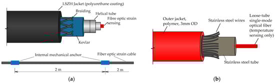
Figure 1.
Fiber optic cables: (a) Inner point strain sensing. (b) Temperature compensation sensing.
Distributed strain and temperature data were acquired using a Brillouin Optical Time-Domain Analyzer (BOTDA class), which tracked the Brillouin frequency shift along the sensing fiber as a proxy for axial strain and temperature [1,2]. The instrument was operated with a nominal spatial sampling interval of 5 ns (≈0.5 m) and fixed pump–probe and averaging settings throughout the entire test, selected to balance noise rejection with the ability to represent steep strain gradients in the vicinity of cracks while maintaining consistency with recommended DFOS practice [3,16,17]. An OTDR unit was used before and after installation to verify optical continuity and detect any potential damage or signal loss.
Surface mounting of the DFOS cable was performed by cutting a shallow longitudinal groove into the soffit and bonding the cable using a two-component structural epoxy conforming to ASTM C881/C881M (Type I/II, Grade 2–3, Class C) [22]. The groove was cleaned, dried, degreased, and primed as recommended by the adhesive manufacturer. Epoxy stiffness and bondline thickness were selected with reference to established DFOS strain-transfer literature emphasizing the influence of adhesive properties on spatial resolution and MTF fidelity under cracking [15,16,17]. Cable handling during installation followed IEC 60794 guidance for optical cables in outdoor structural environments, respecting minimum bend radius and tensile limits to avoid micro-bending and latent damage [23,24].
To benchmark and validate the DFOS response, additional instrumentation included foil strain gauges (FSGs) and vibrating-wire strain gauges (VWSGs) installed at selected positions within the tensile zone, as well as linear variable differential transformers (LVDTs) distributed along the span to record deflection profiles. These discrete sensors provided independent point measurements to cross-check DFOS long-gauge averages and to interpret strain peaks associated with crack formation and propagation [5,6,7,8,9,12,13,14].
All DFOS cables were calibrated prior to installation through controlled axial loading cycles up to ±15,000 µε on instrumented coupons, establishing linear, reversible frequency-shift-to-strain relationships for the specific cable–interrogator pairing and confirming negligible hysteresis within the anticipated operating range [1,2]. Manufacturer-supplied Brillouin coefficients were and . Following installation, unloaded baseline profiles were recorded to fix the zero-reference state for subsequent distributed strain and temperature measurements. The selected combination of G.652 single-mode fiber, steel-wire reinforcement, polymer jacket, and internal fixity architecture was intended to ensure (i) signal continuity and survivability in the presence of discrete flexural cracks; (ii) stable and unbiased section-level strain averages for serviceability and differential-settlement assessment; and (iii) compatibility with Brillouin interrogation over the full 12-m span using sub-meter spatial sampling [1,2,3,15,16,17,19,20,22,23,25].
Detailed technical specifications of all instrumentation are summarized in Table 1, and additional descriptions are provided below.

Table 1.
Technical specifications of all instrumentation used in the experimental program.
2.2. Cable Installation, Test Setup, and Procedures
2.2.1. Specimen Preparation and DFOS Installation
The RC beam described in Section 2.1 was instrumented and tested under four-point bending (Figure 2). A fixed-point DFOS cable was pre-installed by bonding it into a longitudinal groove along the tension face of the beam to enable strain monitoring during loading. The constant-moment region was positioned between the two loading points at 0.4 L and 0.6 L (20–60–20% of the span), corresponding to the distributed fiber-optic sensing (DFOS) segmentation illustrated in Figure 3. Before sensor installation, the concrete surface was ground to sound material, vacuum-cleaned, and dried to ensure consistent bonding conditions.
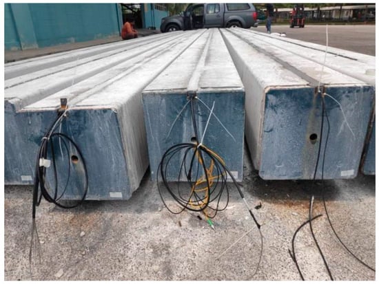
Figure 2.
Full-scale precast RC beams with pre-installed fixed-point DFOS cables bonded in longitudinal grooves prior to load testing.
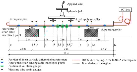
Figure 3.
Schematic of the four-point bending setup and sensor layout.
The four-point bending configuration shown in Figure 3 was specifically selected because it produces a constant-moment region between the two applied loads, allowing flexural cracking to develop in a controlled and repeatable manner. This provides an ideal mechanical environment for evaluating both localized strain peaks and long-gauge averaging behavior of the fixed-point DFOS cable. The geometry corresponds to the third-point loading arrangement in ASTM C78/C78M and is widely used in DFOS studies on RC beams [5,6,7,8,9,10,11,12,13,14]. Furthermore, the resulting flexural response closely represents service-like bending conditions in precast RC piles, girders, and foundation components, which motivated the choice of this configuration for validating the DFOS system.
A longitudinal groove, approximately 30 × 30 mm in cross-section, was cut along the soffit of the beam to accommodate the single-mode fixed-point DFOS cable and a parallel temperature-sensing fiber. The groove was degreased and cleaned of dust; local surface defects were patched and re-ground. A two-component structural epoxy conforming to ASTM C881/C881M (Type I/II, Grade 2–3, Class C) was applied as a thin, uniform bond layer, following recommendations on DFOS strain transfer and spatial resolution in concrete [15,16,17,22]. The adhesive was allowed to cure under laboratory conditions according to the manufacturer’s specifications.
- (1)
- Mechanical properties of concrete and reinforcement
The mechanical properties of the concrete and reinforcement were specified according to the requirements for high-strength precast foundation elements and verified through companion specimen testing and manufacturer certificates.
Concrete strength was confirmed using companion 150 × 300 mm cylinders tested in accordance with ASTM C39. The measured 28-day compressive strength fell within the expected range for Grade 50–60 concrete, with an average cylinder strength f’c = 52–58 MPa. The corresponding elastic modulus, estimated from the measured strength using ACI 318 relationships, was Ec ≈ 33–36 GPa, with a density of ρ ≈ 2400 kg/m3, which is characteristic of normal-weight structural concrete.
Reinforcement consisted of T20 deformed bars manufactured to Grade 400–500 MPa steel specifications, with a nominal yield strength of fy ≈ 420–500 MPa, and a modulus of elasticity Es = 200 GPa. Closed transverse ties (6.5 mm diameter) provided confinement and shear resistance along the full span. These material properties reflect typical values for precast RC piles with design working loads in the 200–260 tons range.
- (2)
- Instrumentation and loading equipment
A 300-kN hydraulic jack equipped with a calibrated load cell (accuracy ±0.5%) was used to apply monotonic loading. The loading rate during each increment was maintained in the range 0.2–0.5 kN/s, followed by a stabilization period of 3–5 min before data acquisition and crack inspection. The load was monitored continuously through the integrated pressure transducer of the hydraulic system.
Linear variable differential transformers (LVDTs) used to record beam deflections had a measurement range of 50 mm and a resolution of 0.01 mm. Foil strain gauges (FSGs) had a nominal resistance of 120 Ω, a gauge factor of 2.0 ± 1% mV/V, and a strain resolution of approximately ±1–3 με. Vibrating-wire strain gauges (VWSGs) provided strain readings with a resolution of ±5–10 με.
All auxiliary sensors (LVDTs, FSGs, VWSGs) were connected to a multi-channel data acquisition unit operating at 1–5 Hz. Calibration of the hydraulic jack, load cell, LVDTs, and FSG/VWSG sensors was performed prior to testing in accordance with the respective manufacturer procedures. These parameters ensure the reliability of the measured mechanical response and allow direct comparison with the DFOS-based strain measurements discussed in the subsequent sections.
The fixed-point DFOS cable (internal fixity spacing = 2.0 m; see Figure 1) was then bonded within the groove. Temporary clips and tape prevented spring-back during curing. Cable handling adhered to IEC 60794 guidance for optical cables [23,24,26] to avoid overstressing or micro-bending losses. After curing, the bonded anchors were inspected, excess epoxy trimmed flush, and a parallel loose-tube fiber positioned to serve as the temperature-reference channel (Figure 3).
Prior to mechanical loading, optical continuity was verified, and unloaded DFOS baselines were recorded three times to establish a zero-strain reference and confirm short-term repeatability. BOTDA interrogation parameters—including the pump pulse width (≈5 ns, corresponding to a spatial resolution of ≈0.5 m), the spatial sampling interval, the number of averages, and other acquisition settings—were kept constant throughout the campaign, following IEC 61757-1-2 terminology and measurand definitions [21].
2.2.2. Four-Point Bending and Data Acquisition
The beam was simply supported on steel rollers, with two line loads applied through a hydraulic jack and load-spreader rollers positioned at 0.4 L and 0.6 L, as shown in Figure 3. Displacements were measured using linear variable differential transformers (LVDTs) installed at nine stations, with higher density near the mid-span. Foil strain gauges (FSG) and vibrating-wire strain gauges (VWSG) were embedded in the tensile zone at representative sections to cross-check DFOS readings. The measurement layout is shown schematically in Figure 3, and detailed sensor specifications are provided in Table 2 and Table 3 [7,9,12,13,14]. The general testing procedure followed established guidelines for quasi-static loading of RC members [27].
Table 2.
Loading sequence.
Table 3.
Summary of Crack-Mapping Observations Corresponding to Each Load Level.
Monotonic loading was applied incrementally as summarized in Table 2, up to a peak load of 57.38 kN. At each load level, a 3–5 min hold period allowed stabilization and crack inspections. During each hold, DFOS strain and temperature profiles were collected as time-averaged traces (several scans per step), while LVDT, FSG, and VWSG measurements were logged continuously. Distributed strain was analyzed as both full-span profiles between internal fixities (IFP1–IFP4) and as long-gauge averages between adjacent fixities (e.g., 1.5 m sub-segments between IFP2–IFP3), consistent with the fixed-point cable concept shown in Figure 1.
2.2.3. Temperature Compensation, Crack Mapping, and Quality Control
Brillouin Optical Time-Domain Analysis (BOTDA) detects strain and temperature by measuring the change in Brillouin frequency shift () along a single-mode fiber. When a pump pulse interacts with a counter-propagating probe wave, stimulated Brillouin scattering produces a localized frequency shift whose magnitude depends on the fiber’s axial strain and temperature. The fundamental sensing relationship is expressed as:
where and are the strain and thermal sensitivity coefficients of the cable–interrogator pair. This equation forms the basis for converting the measured frequency shift into distributed strain and temperature fields.
Calibration of strain and temperature sensitivity coefficients.
Prior to installation, the fixed-point DFOS cable and the companion loose-tube temperature fiber were calibrated together with the BOTDA interrogator (Neubrex NBX-7020, Neubrex Co., Ltd., Kobe, Japan). The calibration was performed on 1.2 m coupon specimens by applying (1) controlled axial tension up to approximately 1500 µε and (2) controlled thermal variations in a 10–40 °C environmental chamber. The resulting sensitivity coefficients were:
- Strain sensitivity: = 0.048 ± 0.002 MHz/µε;
- Temperature sensitivity: = 1.02 ± 0.03 MHz/°C.
Both strain and temperature calibrations exhibited excellent linearity (R2 = 0.998–0.999) and negligible hysteresis during loading–unloading cycles. Repeated zero-load baselines varied within ±20–30 µε, consistent with accepted BOTDA stability benchmarks for ITU-T G.652b fibers. These values were subsequently used for all strain and temperature conversions in the present study.
The spatial resolution of BOTDA is governed by the pump-pulse width; in this study it was 5 ns (≈0.5 m), which defines the minimum length over which strain can be distinguished. Although this scale does not resolve millimeter-sized crack openings, it reliably captures the strain signatures of cracking as sharp peaks within a sub-meter gauge, consistent with DFOS studies on RC members [3,6,7]. BOTDA is therefore appropriate for this experiment because it: (1) provides stable long-gauge measurements between internal fixities, permitting evaluation of global flexural behavior of the fixed-point cable; (2) preserves monotonic sensing even when cracking disrupts bonded discrete gauges.
Typical limitations—meter-scale resolution, attenuation sensitivity, and reliance on stable pump–probe settings—were mitigated by the short sensing length (12 m), constant acquisition parameters, and the use of an ITU-T G.652b fiber. These considerations establish the theoretical foundation for the compensation procedure applied below.
To remove the thermal component from the measured frequency shift, strain was computed using:
where ΔT is the temperature variation recorded by the parallel loose-tube fiber positioned adjacent to the sensing cable (Figure 3). This standard Brillouin compensation procedure follows the terminology and measurand definitions of IEC 61757-1-2 [21].
Crack development was monitored visually within the constant-moment region (highlighted in Figure 3) using a portable crack microscope with a resolution of approximately 0.02–0.05 mm. Crack widths were compared with common serviceability thresholds defined in Eurocode 2 and ACI documents [28,29], although no structural design verification was performed.
Quality assurance required:
- Absence of optical discontinuities or step losses;
- Repeatability of unloaded DFOS baselines within several tens of microstrain;
- Consistency in sign and magnitude between DFOS long-gauge averages and co-located FSG/VWSG readings under low-to-moderate loads.
Acquisition settings remained constant throughout the test, with only the number of time-averaged scans varied between load steps. Although the test specimen represents an RC beam rather than a plain-concrete prism, the four-point configuration geometrically corresponds to the third-point flexure setup described in ASTM C78/C78M, which is cited as an independent reference for span and load geometry [30].
3. Results
The experimental program produced a comprehensive dataset combining distributed and discrete strain measurements, temperature responses, and global deflection records of the reinforced concrete beam under four-point bending. The analysis begins with verification of the optical baselines and signal repeatability, followed by examination of the evolution of distributed strain under incremental loading. Subsequent sections interpret long-gauge strain averages between internal fix points (IFPs), cross-validation with discrete gauges, and temperature compensation behavior, concluding with global deformation profiles obtained from displacement transducers (LVDTs). In contrast to a purely descriptive reporting of measurements, the following sections integrate experimental observations with theoretical expectations from RC flexure mechanics, Brillouin DFOS measurement theory, and previously published DFOS studies on concrete structures [1,2,3,4,5,6,7,8,9,10,11,12,13,14,15,18,19,20,21,22,23,24,25], enabling a more mechanistic interpretation of the observed strain behavior. All loading stages mentioned in this section correspond to the sequence presented in Table 2, and the instrumentation layout is shown in Figure 3.
3.1. Optical Baselines and Repeatability
Prior to mechanical loading, the complete test configuration—including supports, loading points, fiber routing, and anchor fixities—was verified as shown in Figure 3. Brillouin frequency baselines were then recorded along all instrumented segments to establish the zero-strain reference and confirm optical integrity. Representative baseline spectra are presented in Figure 4 and Figure 5, showing smooth, piecewise-uniform frequency distributions without step losses, reflections, or discontinuities attributable to splices or micro-bending effects. The absence of local spectral anomalies indicates proper adhesion of the cable within the groove and stable coupling between the sensing fiber and the host concrete.
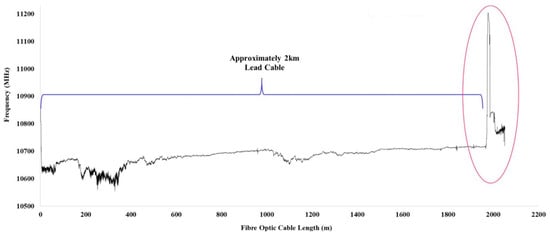
Figure 4.
Nominal frequency of different cables, part 1.
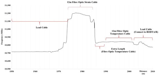
Figure 5.
Nominal frequency of different cables, part 2.
Repeated baseline measurements (three consecutive scans under unloaded conditions) yielded nearly identical frequency responses, with deviations limited to a few megahertz, corresponding to strain repeatability better than several tens of microstrain. This level of agreement is consistent with performance benchmarks reported for Brillouin-based DFOS in concrete environments [1,15,17,22].
From a theoretical perspective, this stability verifies that the mechanical transfer function (MTF) governing strain transmission through the cable construction was in a linear, undamaged regime prior to loading. According to MTF theory [15,16,17], debonding, micro-slippage, or excessive adhesive thickness would manifest as spectral distortions or inconsistent baseline shifts—none of which were observed. Thus, the system reliably met the prerequisite conditions for quantitative Brillouin strain interpretation.
The combined results confirm that both the strain and temperature channels maintained optical continuity along their full lengths, validating the installation procedure and providing a robust baseline for subsequent interpretation of load-induced responses. Repeating unloaded acquisitions confirmed short-term repeatability for both the strain cable (Figure 6) and the temperature channel (Figure 7), consistent with accepted Brillouin DFOS practice for establishing a zero-state prior to mechanical loading [1,2,23].
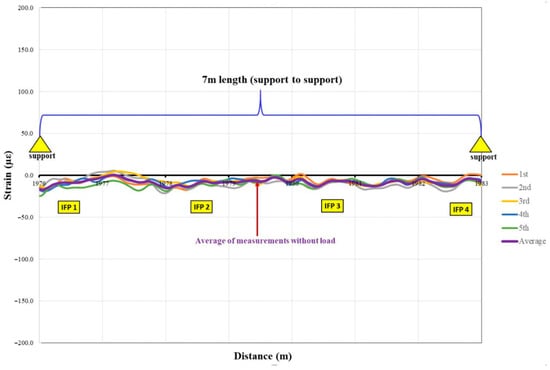
Figure 6.
Repetition of Strain cable measurements without load.
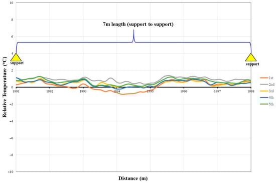
Figure 7.
Repetition of Temperature cable measurements without load.
To further quantify the optical stability of the sensing system, the raw Brillouin frequency shift baselines from three consecutive unloaded measurements are presented in Figure 8a. These profiles represent the direct BOTDA outputs prior to conversion into strain or temperature and allow assessing the intrinsic spectral variability along the entire 12 m fiber.
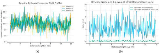
Figure 8.
(a) Baseline Brillouin frequency-shift profiles from three unloaded measurements. (b) Baseline Brillouin frequency-shift profiles from three unloaded measurements.
From these curves, the point-wise standard deviation σ(Δν_B) was computed and subsequently transformed into its equivalent strain and temperature noise by applying the calibrated coefficients and . The resulting distributions are shown in Figure 8b, demonstrating that the equivalent strain noise remains within approximately ±20–30 µε, while the equivalent temperature noise is on the order of ±0.02–0.04 °C. These values fall within the typical performance envelope of short-range BOTDA systems and indicate high baseline precision and stability.
Taken together, the baseline measurements demonstrate that the sensing system was free from optical artefacts, drift, or bonding defects, and was therefore in a valid and calibrated state for assessing the subsequent mechanical response.
3.2. Distributed Strain Evolution and Crack Signatures
Representative distributed strain profiles spanning IFP1–IFP4 are compiled in Figure 6 for load levels from 1.09 to 57.38 kN, with the OTDA spatial sampling of 5 ns (~500 mm) held constant [25]. As load increased, tensile-zone strain grew monotonically, and localized peaks emerged within the constant-moment region (see Figure 9), indicating crack initiation and growth—behavior widely reported for bonded and distributed DFOS on RC beams [5,6,7,8,9].
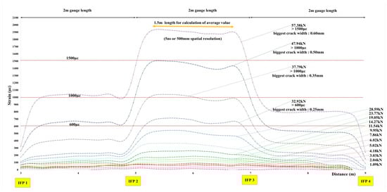
Figure 9.
Fiber optic strain measurement under various loadings.
According to classical RC flexure theory (e.g., moment–curvature/M–κ relationships), cracking initiates when the tensile stress at the extreme fiber exceeds the modulus of rupture, after which tensile strain localizes at crack planes, while the concrete between cracks (“tension stiffening region”) continues to participate in load sharing. This produces steep strain gradients, which DFOS captures as narrow, high-magnitude peaks. The appearance and evolution of such peaks in Figure 9 therefore reflect the theoretical transition from uncracked elastic behavior to cracked-section stiffness degradation.
The most pronounced activity concentrated between IFP2 and IFP3 at 32.92 kN, and the DFOS peak surpassed ~600 µε, coinciding with the first visibly measurable crack widening inside the constant-moment region. As the load increased to 37.79 kN and 57.38 kN, strain peaks exceeded ~1000 µε and ~1500 µε, respectively, matching locations where visual inspection confirmed progressive crack opening. These strain peaks therefore reflect the initiation and propagation of cracking, consistent with previous DFOS studies on RC members [5,6,7,8,9]. No direct quantitative conversion between DFOS strain magnitude and crack width is implied; rather, the peaks serve as qualitative indicators of local damage development.
Peak-magnitude evolution matches predictions from tension-stiffening models and empirical crack-width formulas (e.g., Eurocode 2), where wider cracks correspond to larger local tensile strains in the reinforcement and adjacent concrete. Although the DFOS peak strain does not directly equal reinforcement strain due to MTF smoothing, the monotonic relationship is theoretically consistent.
Table 3 provides a consolidated overview of all crack-mapping observations corresponding to the load levels shown in Figure 9, Figure 10, Figure 11 and Figure 12. For each increment, the table lists the crack status, maximum measured crack width, and the spatial extent of cracking relative to the inner fixed points (IFP1–IFP4). This information allows straightforward correlation between the localized strain peaks identified by DFOS and the actual crack formation and widening observed on the beam surface, thereby supporting the interpretation of distributed and long-gauge strain responses.
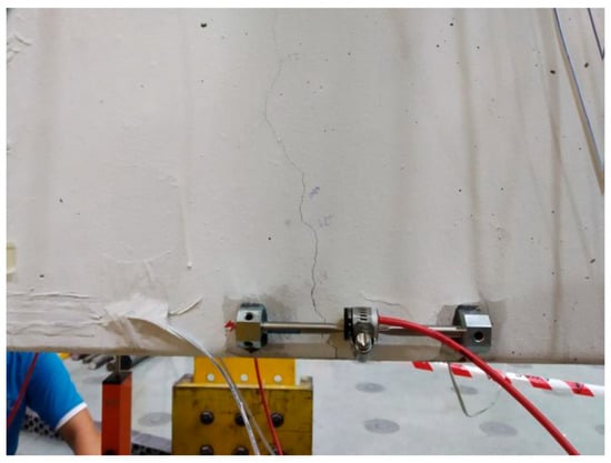
Figure 10.
Representative flexural crack observed during the loading stage near VWSG-3 (within the IFP2–IFP3 region), corresponding to the dominant strain-peak zone captured by DFOS.
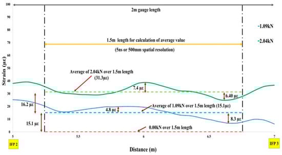
Figure 11.
Average of fiber optic strain cable for IFP2−IFP3 under loads 0 kN to 2 kN to observe measurements < 22 µε.
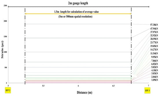
Figure 12.
Average of Fiber Optic Strain Cable for IFP2−IFP3 under various Loads.
To complement the crack-mapping summary presented in Table 3 and to provide direct visual evidence of the observed damage, Figure 10 shows a representative flexural crack that developed in the constant-moment region near VWSG-3 at higher load levels. The crack is located within the IFP2–IFP3 zone where the distributed DFOS profiles exhibit the highest localized strain peaks (Figure 9), confirming the spatial correspondence between measured strain concentrations and actual crack formation.
The spatial match between DFOS peaks and crack-mapping zones confirms that strain localization was not an artefact of sensor debonding but rather a true mechanical response. This correlation strengthens the interpretation of DFOS as a crack-indication tool consistent with previous beam studies [5,6,7,8,9,10,11,12,13,14].
3.3. Long-Gauge Averaging Between Fixities
To quantify section-level behavior, a 2.0 m gauge between IFP2–IFP3 was analyzed, with a 1.5 m sub-segment used for averages. At low loads, averages were near zero and scaled proportionally with the applied load—e.g., 0.0 µε at 0.00 kN, 15.1 µε at 1.09 kN, and 31.3 µε at 2.04 kN (Figure 11).
This linearity is theoretically expected in the uncracked regime, where RC flexure remains governed by the gross-section moment of inertia. Long-gauge DFOS thus behaves analogously to conventional long-gauge sensors (e.g., SOFO), which filter local strain fluctuations and reflect global curvature.
Over the full loading range, averaged profiles for each step (1.09–57.38 kN) are shown in Figure 12, demonstrating stable, progressive growth without sign inversions or plateaus.
The resulting load–strain regression in Figure 13 is strongly linear (R2 = 0.9907), with minor outliers at 3.03 and 7.86 kN—consistent with transient settling and the onset of microcracking noted in distributed profiles (Figure 9) and in the literature on early nonlinearity under flexure [5,6,7,8,9,12,13,14].
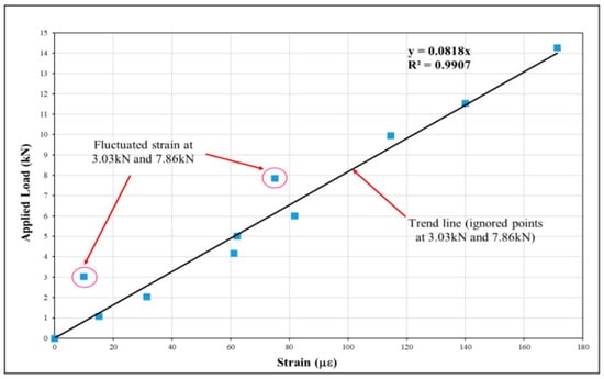
Figure 13.
Graph of applied load vs. average (small) strain for IFP2-IFP3.
To address the localized behavior more explicitly, this load–strain relationship represents the IFP2–IFP3 gauge, located within the constant-moment region where cracking was most pronounced according to the mapping diagrams (Table 3). This section consistently exhibited the highest tensile demand and therefore provides a representative cross-section for evaluating DFOS response under flexure. The strong linearity of the regression confirms that the fixed-point cable accurately captured the global flexural stiffness, while the minor deviations at 3.03 kN and 7.86 kN align with the first appearance of hairline cracks and the localized strain peaks in the distributed profiles. Taken together, the distributed signatures (Figure 9), the crack maps, and the load–strain curve in Figure 13 provide a coherent description of how strain localizes and propagates as cracking advances.
This level of linearity matches analytical expectations from cracked-section theory, where the moment–curvature response of RC sections remains nearly linear through moderate cracking as tension stiffening bridges early crack growth. Only at extensive cracking would significant curvature softening occur, which was not reached in this test. Thus, the DFOS long-gauge output reflects the theoretical “global stiffness” behavior of the beam.
Overall, the fixed-point DFOS system provided stable and drift-free long-gauge strain measurements throughout the entire loading range. The absence of sign inversions or plateau effects confirms that the inner-fixity configuration can reliably capture global flexural behaviour of RC members, while remaining insensitive to local cracking-induced discontinuities. This supports its applicability for section-level strain monitoring and serviceability assessment in RC foundations.
3.4. Comparison with Discrete Gauges
To validate the DFOS measurements and assess their compatibility with conventional instrumentation, the long-gauge DFOS strains were compared with readings from co-located foil strain gauges (FSGs) and vibrating-wire strain gauges (VWSGs) installed in the tensile zone. This comparison allows evaluating both the accuracy and robustness of the fixed-point DFOS approach in relation to established sensing technologies. A summary of DFOS averages and FSG measurements is presented in Table 4.
Table 4.
Strain Measurements of Fiber Optic Strain Cable, Foil Strain Gauge 6 & 14.
Agreement was strong across the range—for example, at 28.59 kN, DFOS reported 509 µε versus 508 µε (FSG 6) and 445 µε (FSG 14). VWSGs (Table 5) showed the same monotonic trend, reaching average values up to ~3149 µε at the peak load; higher absolute values are attributed to positional differences and intrinsic gage mechanics, as commonly discussed for vibrating-wire sensors versus bonded strain measurements [7,13,14]. This systematic offset between DFOS, FSG, and VWSG readings is consistent with theoretical expectations: DFOS and foil gauges sense surface or near-surface strains over finite gauge lengths, whereas VWSGs are more directly influenced by reinforcement strain and local curvature, leading to higher recorded values in heavily cracked regions.
Table 5.
Strain Measurements of Fiber Optic Strain Cable, Foil Strain Gauge 3 & 4.
The composite comparison in Figure 14 highlights that DFOS maintained continuity and monotonicity through crack formation, whereas some discrete gauges displayed saturation, scatter, or sign changes in zones influenced by localized cracking—an effect also noted in RC DFOS case studies [5,6,7,8,9,12,13,14].
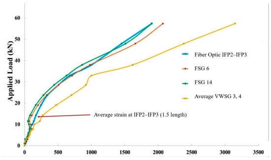
Figure 14.
Comparison of strain measurements between fiber optic strain sensing cable and strain gauges.
Figure 14 shows that DFOS maintained continuity where discrete sensors experienced scatter or saturation—a classical DFOS advantage documented in [5,6,7,8,9,10,11,12,13,14]. From a structural point of view, this behavior reflects the fact that the fixed-point DFOS integrates strain between anchors and is therefore less sensitive to local debonding or stress concentrations at individual cracks, whereas point sensors can be strongly affected by their exact position relative to crack planes. The overall agreement in trend, combined with the enhanced continuity of DFOS, supports the use of fixed-point DFOS as a reliable complement to conventional gauges for serviceability assessment and crack-zone monitoring.
3.5. Temperature Behavior and Compensation
The companion temperature channel recorded diurnal and test-related variations from 12:00 to 18:00 local time (Figure 15).
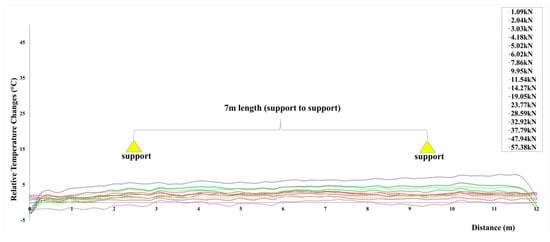
Figure 15.
Fiber optic temperature measurement under various loadings (From 12 p.m.–6 p.m.).
These readings were used for linear temperature compensation of Brillouin frequency shifts, per the calibrated coefficients of the cable/interrogator pair (Section 2.2.3) and the terminology in IEC 61757-1-2 [21]. No spurious thermal transients coincident with rapid load changes were detected, supporting the assumption of quasi-static thermo-mechanical separation during holds.
Figure 16 illustrates the direct effect of the compensation procedure. The uncompensated profile shows a uniform upward bias of approximately 20–40 µε caused by the gradual temperature increase recorded in Figure 16. After compensation, the baseline is restored to near zero across the span, while the mechanically induced peak associated with cracking remains unchanged. This confirms that temperature compensation effectively removes thermal bias without altering the physical strain signature.
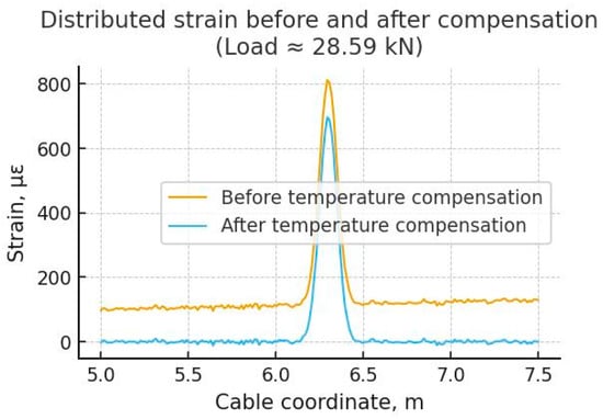
Figure 16.
Strain distribution before and after temperature compensation (Load ≈ 28.59 kN).
Figure 17 shows the stability of the thermally compensated strain profiles during three representative load-hold intervals (11.54 kN, 28.59 kN, and 47.94 kN). Across all holds, the compensated strain remains steady, with no detectable drift or fluctuation in the baseline. This demonstrates that the temperature-compensation fiber provides reliable real-time thermal referencing and ensures that the reported DFOS strain evolution in Section 3.2, Section 3.3 and Section 3.4 reflects true mechanical behavior rather than temperature-related artefacts.
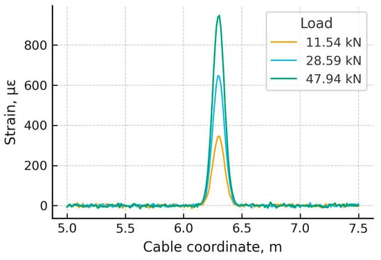
Figure 17.
Stability of compensated strain during load-hold phases.
3.6. Global Deformation from LVDTs
To evaluate the global flexural response, vertical displacements were recorded by nine LVDTs along the span of the beam. The deflected shape derived from these measurements is shown in Figure 18 for all applied load stages.
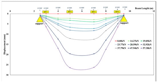
Figure 18.
Beam displacements measured using LVDT.
As expected for a simply supported four-point configuration (Figure 3), the deformation was symmetric with a maximum near mid-span (between LVDT 4 and LVDT 6). The mid-span load–deflection curve (Figure 19) exhibited an initial near-linear regime up to ~20 kN, followed by stiffness reduction as cracking progressed; beyond ~30 kN, nonlinearity increased, consistent with flexural crack development and internal stress redistribution. The smooth progression without abrupt softening corroborates the distributed strain findings (Figure 9) and matches typical RC flexural behavior reported in the literature [7,9,13,14]. This evolution of stiffness is also compatible with classical moment–curvature relationships for RC sections, where the transition from uncracked to cracked behavior leads to gradual rather than sudden reductions in flexural rigidity.
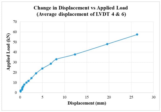
Figure 19.
Change in displacement vs. applied load.
Taken together, the results confirm that the fixed-point DFOS captured both global behavior (long-gauge averages with R2 ≈ 0.99 in Figure 13) and local damage signatures (peak strains/crack indicators in Figure 9), remained consistent with discrete gauges (Table 4 and Table 5, Figure 14), and was thermally stable after compensation (Figure 15). These outcomes are in line with previously reported DFOS performance on RC members [3,5,6,7,8,12,13] and with Brillou. The same kind is highlighted below in DFOS measurement conventions [1,2,21], supporting the suitability of the approach for SHM of concrete foundation elements. The combined agreement between DFOS, discrete gauges, and LVDT-based global deformations provides a coherent experimental validation of the fixed-point DFOS concept under flexural loading and demonstrates its potential to supply both section-averaged and crack-sensitive information required for performance-based assessment of RC foundations.
4. Discussion
The findings of this study have direct implications for the structural health monitoring (SHM) of reinforced concrete (RC) foundations, including piles, footings, and slabs. In such elements, where operational continuity, robustness through cracking, and reliable long-gauge strain measurements are critical, the fixed-point DFOS configuration demonstrates distinct advantages. It provides dense and spatially distributed coverage capable of identifying localized “hot zones” of strain concentration (for example, between IFP2 and IFP3 in Figure 9) while simultaneously offering stable section-level strain averages suitable for evaluating serviceability and differential settlement (see Figure 13). Moreover, the cable’s internal fixity concept ensures resilience to localized damage, as reflected by its consistent agreement with discrete strain gauges throughout the loading sequence (Figure 14, Figure 20, Figure 21 and Figure 22, Table 4 and Table 5). These attributes align closely with emerging digital twin frameworks that depend on spatially rich and drift-managed strain fields for prognosis, maintenance planning, and life-cycle performance analytics [1,2,3,4,12,13,18].
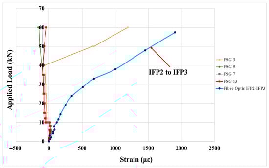
Figure 20.
Selected conventional strain gauges with abnormal measurements vs. IFP2–IFP3 measurement.
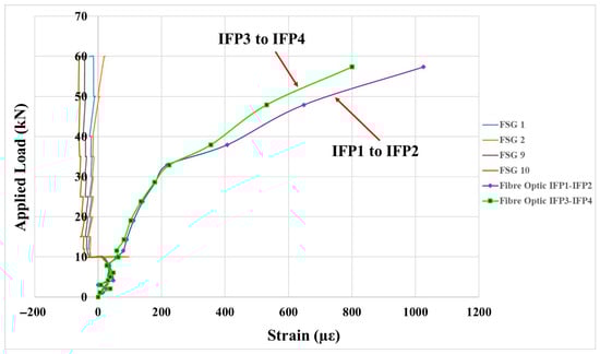
Figure 21.
Selected conventional strain gauges with abnormal measurements vs. IFP1–IFP2 and IFP3–IFP4 measurements.
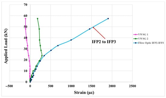
Figure 22.
Vibrating wire strain gauges with abnormal measurements vs. IFP2–IFP3 measurement.
Nevertheless, certain limitations must be recognized. The intrinsic averaging between internal fixities may under-resolve clusters of narrow microcracks, especially at early stages of flexural cracking. To overcome this, a practical next step is the development of hybrid multi-scale monitoring layouts—combining short-gauge DFOS patches at critical high-risk zones with a fixed-point “backbone” for overall continuity. Such configurations remain fully compatible with prior DFOS deployments in reinforced concrete structures [3,5,6,7,8,9,12,13,14,16].
Further improvements could involve incorporating calibrated modulation transfer function (MTF) corrections and automated crack-width inference routines [5,6,7,8,9,15,16,17], thereby enhancing the quantitative correlation between DFOS strain peaks and visually observed crack patterns. In addition, long-term field monitoring under environmental cycling and variable humidity would provide valuable benchmarks for assessing durability, temperature compensation, and baseline stability over time [3,8,21].
Overall, the present experimental campaign confirms that the inner fixed-point DFOS configuration can simultaneously capture both robust long-gauge strain metrics and sensitive crack-related strain gradients in reinforced concrete under flexure. Its performance aligns well with the broader DFOS literature [1,2,3,4,5,6,7,8,9,10,11,12,13,14] and complies with best practices for strain transfer, gauge length selection, and thermal management [11,15,16,17,19,20,23]. Therefore, the fixed-point DFOS approach represents a durable and SHM-ready solution for monitoring concrete foundation systems—one that complements traditional discrete instrumentation rather than replaces it, contributing to more resilient, data-enriched, and life-cycle-aware infrastructure management.
5. Conclusions
This study verified that a fixed-point DFOS cable installed on a full-scale RC beam can concurrently deliver robust long-gauge strain metrics and sensitive crack indicators under four-point bending. The approach combined Brillouin time-domain interrogation with inner mechanical fixities at 2 m spacing and epoxy bonding in a shallow surface groove.
Main conclusions based on experimental Figures and Tables:
Global strain response exhibited high linearity with applied load (R2 ≈ 0.99), with only minor deviations at early load stages (Figure 13), consistent with DFOS trends reported for RC members [3,5,6,7,8,12,13].
Distributed strain profiles captured the initiation and evolution of cracking, with characteristic DFOS strain peaks of approximately ~600, ~1000, and ~1500 µε, each coinciding with visually observed stages of crack development within the constant-moment region (Figure 9).
DFOS long-gauge strains closely matched foil strain gauges and followed the same trend as vibrating-wire gauges (Table 4 and Table 5, Figure 14). At higher loads and through cracking, DFOS maintained signal continuity where discrete sensors showed saturation or scatter (Figure 20, Figure 21 and Figure 22).
Temperature compensation using the companion fiber ensured stable readings, with no thermal artefacts during load holds (Figure 15).
LVDT-based deflection curves and global deformation shapes (Figure 18 and Figure 19) corroborated the DFOS-based strain interpretation and reflected typical RC flexural behavior.
Implications for SHM of RC foundations. The findings of this study indicate that the inner fixed-point DFOS architecture is well suited for structural health monitoring of reinforced concrete foundations such as piles, footings and slabs. In such elements—where uninterrupted operation, durability in the presence of cracking, and reliable long-gauge strain measurements are critical—the proposed system offers three key benefits:
- Dense distributed sensing that enables localization of strain “hot zones”;
- Stable section-level strain averages suitable for serviceability and differential-settlement evaluation;
These attributes are directly compatible with emerging digital-twin practices that depend on spatially rich and drift-controlled strain data for prognosis and life-cycle asset management.
Limitations and future work. Despite these advantages, the intrinsic averaging between internal fixities may under-represent clusters of closely spaced microcracks. A practical improvement is a multi-scale sensing layout that combines short-gauge DFOS segments at high-risk zones with a fixed-point backbone for global continuity. Further developments should also include transfer-function–based calibration to strengthen quantitative links between DFOS strain peaks and crack widths [5,6,7,8,9,15,16,17], and long-term field monitoring to assess seasonal and environmental stability of measurements [3,18,21].
Overall, inner fixed-point DFOS has proven to be a durable, SHM-ready sensing solution for concrete structures, capable of capturing both macro-scale deformation and localized cracking. Rather than replacing discrete gauges, it complements them, offering a continuous data backbone consistent with established DFOS evidence [1,2,3,4,5,6,7,8,9,10,11,12,13,14] and supporting its implementation in predictive, digital twin-enabled management of RC foundations.
Author Contributions
Conceptualization, A.B. and B.P.T.; methodology, A.S.; software, G.O.; validation A.B., I.Z. and B.P.T.; formal analysis A.S.; investigation, I.Z. and B.P.T.; resources, G.O.; data curation, A.S.; writing—original draft preparation, A.B. and B.P.T.; writing—review and editing, A.S.; visualization, I.Z. and B.P.T.; supervision, A.B.; project administration, A.B.; funding acquisition, A.B., B.P.T. and G.O. All authors have read and agreed to the published version of the manuscript.
Funding
This work was funded by the Committee of Science of the Ministry of Science and Higher Education of the Republic of Kazakhstan (Grant No. AP22688230).
Data Availability Statement
The raw data supporting the conclusions of this article will be made available by the authors upon request.
Acknowledgments
The authors gratefully acknowledge Smart Sensing Technology Sdn Bhd (Shah Alam, Malaysia) for their technical advice and cooperation, in particular B.P.T., for his assistance related to DFOS installation and signal interpretation. The experimental work was supported by the field engineering team and subcontractors involved in the DFOS cable installation, bonding, and load testing procedures. Their practical expertise and on-site coordination greatly contributed to the successful execution of the test program.
Conflicts of Interest
Author Bun Pin Tee was employed by the company Smart Sensing Technology Sdn Bhd. The remaining authors declare that the research was conducted in the absence of any commercial or financial relationships that could be construed as a potential conflict of interest.
References
- Bao, X.; Chen, L. Recent Progress in Distributed Fiber Optic Sensors. Sensors 2012, 12, 8601–8639. [Google Scholar] [CrossRef] [PubMed]
- Motil, A.; Bergman, A.; Tur, M. State of the Art of Brillouin Fiber-Optic Distributed Sensing. Opt. Laser Technol. 2016, 78, 81–103. [Google Scholar] [CrossRef]
- Palmieri, L.; Schenato, L. Rayleigh-Based Distributed Optical Fiber Sensing. Sensors 2022, 22, 6811. [Google Scholar] [CrossRef] [PubMed]
- Barrias, A.; Casas, J.R.; Villalba, S. A Review of Distributed Optical Fiber Sensors for Civil Engineering Applications. Sensors 2016, 16, 748. [Google Scholar] [CrossRef] [PubMed]
- Berrocal, C.G.; Fernandez, I.; Rempling, R. Crack Monitoring in Reinforced Concrete Beams by Distributed Optical Fiber Sensors. Struct. Infrastruct. Eng. 2021, 17, 102–122. [Google Scholar] [CrossRef]
- Liu, T.; Huang, H.; Yang, Y. Crack Detection of Reinforced Concrete Member Using Rayleigh-Based Distributed Optic Fiber Strain Sensing System. Adv. Civ. Eng. 2020, 2020, 8312487. [Google Scholar] [CrossRef]
- Brault, A.; Hoult, N.A. Monitoring Reinforced Concrete Serviceability Performance Using Fiber-Optic Sensors. ACI Struct. J. 2019, 116, 57–70. [Google Scholar] [CrossRef]
- Buranbayeva, A.; Zhussupbekov, A.; Sarsembayeva, A.; Omarov, A. Evaluation of the Structural Health Monitoring Results of the Applied Fiber Optics in the Pile-Raft Foundations of a High-Rise Building. Appl. Sci. 2022, 12, 11728. [Google Scholar] [CrossRef]
- Regier, R.; Hoult, N.A. Distributed Strain Behavior of a Reinforced Concrete Bridge: Case Study. J. Bridge Eng. 2014, 19, 05014007. [Google Scholar] [CrossRef]
- Hénault, J.M.; Quiertant, M.; Delepine-Lesoille, S.; Salin, J.; Moreau, G.; Taillade, F.; Benzarti, K. Quantitative Strain Measurement and Crack Detection in RC Structures Using a Truly Distributed Fiber Optic Sensing System. Constr. Build. Mater. 2012, 37, 916–923. [Google Scholar] [CrossRef]
- Monsberger, C.M.; Lienhart, W. Distributed Fiber Optic Shape Sensing of Concrete Structures. Sensors 2021, 21, 6098. [Google Scholar] [CrossRef] [PubMed]
- Hénault, J.M.; Quiertant, M.; Salin, J.; Moreau, G.; Taillade, F.; Delepine-Lesoille, S.; Benzarti, K. Analysis of the Strain Transfer Mechanism Between a Truly Distributed Optical Fiber Sensor and the Embedding Medium. In Proceedings of the 9th International Conference on NDE in Relation to Structural Integrity for Nuclear and Pressurized Components, Seattle, WA, USA, 22–24 May 2012; Available online: https://www.ndt.net/?id=14790 (accessed on 15 October 2025).
- Butler, L.J.; Gibbons, N.; He, P.; Middleton, C.; Elshafie, M.Z.E.B. Evaluating the Early-Age Behaviour of Prestressed Concrete Beams Using Distributed and Discrete Fiber Optic Sensors. Constr. Build. Mater. 2016, 126, 894–912. [Google Scholar] [CrossRef]
- Webb, G.T.; Vardanega, P.J.; Hoult, N.A.; Fidler, P.R.A.; Bennett, P.J.; Middleton, C.R. Analysis of Fiber-Optic Strain-Monitoring Data from a Prestressed Concrete Bridge. J. Bridge Eng. 2017, 22, 05017002. [Google Scholar] [CrossRef]
- Billon, A.; Hénault, J.M.; Quiertant, M.; Taillade, F.; Khadour, A.; Martin, R.P.; Benzarti, K. Qualification of a Distributed Optical Fiber Sensor Bonded to the Surface of a Concrete Structure: A Methodology to Obtain Quantitative Strain Measurements. Smart Mater. Struct. 2015, 24, 115001. [Google Scholar] [CrossRef]
- Barrias, A.; Casas, J.R.; Villalba, S. Distributed Optical Fiber Sensors in Concrete Structures: Performance of Bonding Adhesives and Influence of Spatial Resolution. Struct. Control. Health Monit. 2019, 26, e2310. [Google Scholar] [CrossRef]
- Bassil, A.; Chapeleau, X.; Leduc, D.; Abraham, O. Concrete Crack Monitoring Using a Novel Strain-Transfer Model for Distributed Fiber Optics Sensors. Sensors 2020, 20, 2220. [Google Scholar] [CrossRef] [PubMed]
- Fernandez, I.; Berrocal, C.G.; Rempling, R. Long-Term Performance of Distributed Optical Fiber Sensors Embedded in Reinforced Concrete Beams Under Sustained Deflection and Cyclic Loading. Sensors 2021, 21, 6338. [Google Scholar] [CrossRef] [PubMed]
- Glišić, B.; Inaudi, D. Fiber Optic Methods for Structural Health Monitoring; Wiley: Chichester, UK, 2007. [Google Scholar] [CrossRef]
- Inaudi, D.; Glisic, B. Long-Gage Sensor Topologies for Structural Monitoring. In Proceedings of the Fib Congress, Osaka, Japan, 13–19 October 2002. [Google Scholar]
- IEC 61757-1-2:2023; Fiber Optic Sensors—Part 1–2: Strain Measurement—Distributed Sensing Based on Brillouin Scattering. International Electrotechnical Commission: Geneva, Switzerland, 2023. Available online: https://webstore.iec.ch/en/publication/30634 (accessed on 15 October 2025).
- ASTM C881/C881M-20; Standard Specification for Epoxy-Resin-Base Bonding Systems for Concrete. ASTM International: West Conshohocken, PA, USA, 2020. Available online: https://www.astm.org/c0881_c0881m-20.html (accessed on 14 October 2025).
- IEC 60794-3; Optical Fiber Cables—Part 3: Outdoor Cables. International Electrotechnical Commission: Geneva, Switzerland, 2020. Available online: https://webstore.iec.ch/publication/66627 (accessed on 14 October 2025).
- IEC 60794-1-111:2023; Optical Fiber Cables—Part 1–111: Generic Specification—Basic Optical Cable Test Procedures—Bending Around a Mandrel. International Electrotechnical Commission: Geneva, Switzerland, 2023. Available online: https://webstore.iec.ch/en/publication/77493 (accessed on 15 October 2025).
- Recommendation ITU-T G.652; Characteristics of a Single-Mode Optical Fiber and Cable. International Telecommunication Union: Geneva, Switzerland, 2016. Available online: https://www.itu.int/rec/T-REC-G.652 (accessed on 14 October 2025).
- IAEA. Guidebook on Non-Destructive Testing of Concrete Structures; Training Course Series No. 17; International Atomic Energy Agency: Vienna, Austria, 2002; Available online: https://www-pub.iaea.org/MTCD/Publications/PDF/TCS-17_web.pdf (accessed on 15 October 2025).
- ACI 374.2R-13; Guide for Testing Reinforced Concrete Structural Elements Under Slowly Applied Simulated Seismic Loads. ACI Committee 374; Preview; American Concrete Institute: Farmington Hills, MI, USA, 2013. Available online: https://www.concrete.org/Portals/0/Files/PDF/Previews/3742R-13_PREVIEW.pdf (accessed on 15 October 2025).
- EN 1992-1-1:2004; Eurocode 2—Design of Concrete Structures—Part 1–1: General Rules and Rules for Buildings. European Committee for Standardization: Brussels, Belgium, 2004. Available online: https://www.phd.eng.br/wp-content/uploads/2015/12/en.1992.1.1.2004.pdf (accessed on 15 October 2025).
- ACI 224R-01; Control of Cracking in Concrete Structures. ACI Committee 224. Reapproved; American Concrete Institute: Farmington Hills, MI, USA, 2001.
- ASTM C78/C78M-22; Standard Test Method for Flexural Strength of Concrete (Using Simple Beam with Third-Point Loading). ASTM International: West Conshohocken, PA, USA, 2022. Available online: https://www.astm.org/c0078_c0078m-22.html (accessed on 15 October 2025).
Disclaimer/Publisher’s Note: The statements, opinions and data contained in all publications are solely those of the individual author(s) and contributor(s) and not of MDPI and/or the editor(s). MDPI and/or the editor(s) disclaim responsibility for any injury to people or property resulting from any ideas, methods, instructions or products referred to in the content. |
© 2025 by the authors. Licensee MDPI, Basel, Switzerland. This article is an open access article distributed under the terms and conditions of the Creative Commons Attribution (CC BY) license (https://creativecommons.org/licenses/by/4.0/).