Abstract
Electroless nickel plating with a nanofinished surface is used in space mirrors, automobile parts, aircraft components, optical instruments, and electronic equipment. Finishing of these components using conventional finishing techniques is limited due to size, shape, material, and process constraints. This work reports the nanofinishing of electroless nickel-plated surfaces using a magnetorheological finishing process where the surfaces are pre-treated with chemicals. The chemicals used in this work are hydrogen peroxide (H2O2) and hydrofluoric acid (HF). The effect of exposure time and concentration on the microhardness and roughness is studied to understand the surface chemistry after chemical treatment. The hydrogen peroxide forms a passivated layer, and it helps in easy material removal. Hydrofluoric acid improves surface quality and also helps in the removal of contaminants. The finished surface is characterized to understand the effect of chemical treatment on the finishing rate and surface topography. Normal and tangential forces are mainly affected by the hardness and surface condition after the chemical treatment. The best combination of parameters (chemical treatment with 1% HF for 30 min) was obtained and finishing was carried out to obtain a nanofinished surface with its areal surface roughness (Sa) reduced to 10 nm.
1. Introduction
Electroless nickel plating involves the chemical reduction of nickel ions in the presence of a chemical reducing agent dissolved in an aqueous solution. Sodium hypophosphite is generally used as the reducing agent for electroless nickel plating. It releases hydrogen during the reaction, which is then oxidized to produce a negative charge on the substrate surface. The reduction process is followed by the deposition of nickel on the substrate. As the process is independent of current distribution, the electroless nickel plating has a uniform thickness irrespective of the shape and size of the substrate surface [1,2]. The commonly used electroless nickel plating involves the deposition of a nickel–phosphorus composite layer where different weight percentages of phosphorus ranging from 2–5% (low), 6–9% (medium), and 10–14% (high) are added to obtain different metallurgical properties to the plated surface. The plated surface, having a low phosphorus concentration, is the hardest and better resistant to wear, whereas the surface with a high phosphorus concentration has better corrosion resistance [3]. Due to excellent mechanical, physical, chemical, and thermal properties, nickel plated surfaces are widely used in electronic components, automobiles, aerospace components, space mirrors, optics, printed circuit boards (PCBs), and marine applications [4]. The surface quality of the metal mirror is greatly improved by electroless nickel plating. Due to difficulties in finishing the substrate itself, the metal mirror materials are plated with electroless nickel to achieve the required optical properties of the finished surface.
The electroless nickel-plated surfaces are finished using different techniques such as single point diamond turning (SPDT), magnetorheological finishing (MRF), and chemical mechanical polishing (CMP). The major problem with SPDT is the tool marks on the finished surface that limit the use of mirrors in the ultraviolet-visible (UV) spectrum. Both MRF and CMP are successfully utilized for the finishing of nickel and its alloys. However, certain drawbacks of these processes, such as limitations on the workpiece geometry in the CMP and higher abrading forces in the MRF, can be eliminated with the help of magnetorheological finishing after chemical treatment [5]. Magnetorheological finishing (MRF) is a precision finishing technique for optical components. This process can be used to finish different workpiece materials varying in shapes and sizes [6,7,8]. The MRF process is carried out in the presence of magnetorheological (MR) fluid, which consists of carbonyl iron particles (CIPs) and abrasive particles thoroughly mixed in a carrier liquid [9]. The CIPs are magnetic and are responsible for magnetorheological effects. The abrasive particles are non-magnetic and help in material removal by mechanical action. The additives are added to the fluid depending upon the applications. The MR fluid shows the behaviour of a Newtonian viscous fluid in the absence of a magnetic field [10]. Introducing a magnetic field leads to the magnetization of CIP particles [11] and chain-like structures are created along the magnetic flux lines [12]. The behaviour of MR fluid in the presence of a magnetic field is similar to that of viscoplastic fluid. Material removal occurs when the workpiece comes into contact with stiffened MR fluid. The penetration of abrasive particles and shearing action lead to material removal. The MRF process is also used for finishing of brittle and ductile materials [13,14,15]. With the development of the process, chemicals are also used in magnetorheological finishing to assist in material removal. However, the material removal rate is mainly affected by process parameters, MR fluid composition, and workpiece material properties.
A corrosion inhibitor such as Benzotriazole (BTA) is also used during the MRF of metal surfaces to protect the finished surface from corrosion and particle disintegration [16]. The different chemicals are utilized for nickel and its alloys during the CMP process. Perchloric acid, benzotriazole, nitric acid, hydrogen peroxide, hydrochloric acid, and hydrofluoric acid have been used in previous studies [17,18]. Zhang et al. [19] used hydrogen peroxide along with malic acid in the CMP slurry for polishing of nickel alloys. It was observed that both chemical and mechanical action help in achieving a surface finish at an angstrom level in a 71 × 53 µm2 scan area. Xu et al. [20] theoretically studied the relationship between the chemical and mechanical effects on nickel phosphorus coating. High-precision and efficient finishing were obtained on electroless nickel-plated metal mirrors using hydrogen peroxide (H2O2) as an oxidant in the smoothing–polishing process. The combined chemical–mechanical action helps in achieving ultra-precision finishing of the electroless nickel plating on the metal mirrors. Hu et al. [21] utilized a series of finishing processes, which included SPDT, MRF, and computer-controlled optical surfacing (CCOS) for finishing of nickel-plated metallic mirrors. It is observed that hydrogen peroxide in the CCOS forms an oxide film that is easier to remove and also helps in protecting the surface from processing damage. A surface roughness of 53 nm is achieved on hard WC-Co coatings using chemically assisted shape-adaptive grinding (CA-SAG), using Murakami’s reagent as the chemical for the etching [22,23]. Moreover, it is stated that the decrease in hardness significantly affects the material removal. The literature on the finishing of nickel-plated surfaces after chemical treatment using magnetorheological finishing are limited, and this creates a scope for exploring the effect of chemicals on the finishing performance and different properties of the surface.
The material removal efficiency and surface quality during the finishing of nickel-plated surfaces are low owing to hard segments present in the bonded structure. Better surface quality and finishing efficiency can be obtained by chemically treating the required surface, which results in lower hardness due to the formation of a passivation layer on the top surface. Moreover, the material removal becomes easier, and the oxide film acts as a protective layer. Further surface damage can be avoided with the help of this protective layer. In the present work, MRF was used for finishing of a electroless nickel–phosphorus-plated stainless steel surface. The surface was chemically treated before the MRF using different chemicals: hydrogen peroxide (H2O2) and hydrofluoric acid (HF). The concentration of H2O2 was taken as 15%, while HF had two different levels of 1% and 5%. These chemicals facilitated the formation of a passivated layer on a nickel–phosphorus-plated surface. The machining parameters were selected based on the literature and kept constant during experimentation. The primary objective of this work is to analyse the finishing rate of MRF process with or without chemical treatment of the surface. It is assumed that the use of these chemicals modify the surface, and a significant change in the properties can be obtained for the chemically treated surface. Moreover, the hardness and surface roughness of the finished surface are of utmost importance. This work proposes an effective finishing method involving chemical treatment to the surface and the MRF process, which can efficiently finish the electroless nickel–phosphorus-plated surface to a nanoscale quickly and without any processing damage to the surface.
2. Materials and Methods
2.1. Characterization of Electroless Plating
A low-carbon alloy of steel based on nickel, chromium, and molybdenum called stainless steel (SS316L) has high temperature strength, better resistance to corrosion and oxidation, and good thermal properties. SS316L samples were cut into the shape of a disc with a 40 mm diameter and a 7 mm thickness by wire-cut electrical discharge machining. All the samples were polished using silicon carbide polishing paper to have even surfaces and cleaned with acetone. The electroless plating procedure was used to deposit a nickel–phosphorus coating onto the stainless steel (SS316L) substrate. The phosphorus content is responsible for the structure of the coated surface. High phosphorus content results in an amorphous structure, whereas low phosphorus content results in a crystal structure.
2.2. Chemical Treatment of Plated Surface
The schematic of chemical treatment and surface cleaning is shown in Figure 1. The nickel-plated surface was cleaned before and completely immersed in the chemical solutions and taken out after the prescribed times. The chemically treated samples were washed with deionized water and then thoroughly cleaned using acetone.
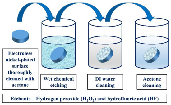
Figure 1.
Schematic of wet chemical treatment of electroless nickel-plated surface.
The chemicals were selected based on the affinity of the nickel surface. These two chemicals are different in terms of their application to the nickel-plated surface. The details of chemical formulation are listed in Table 1.

Table 1.
Details of chemical treatment.
H2O2 is considered a gentle etchant, whereas HF is highly corrosive and toxic if used in higher concentrations. H2O2 is considered safe considering the environment and operator. It is observed that a higher concentration of HF is not environmentally friendly. It is essential to use chemicals that ensure the safety of the operator and prevent the surface from corrosion and other adverse effects. Therefore, lower concentrations of HF were used to ensure safe handling and a controlled chemical reaction. Microhardness tests were performed using an OMNITECH semiautomatic micro hardness tester (MVH-S Auto) on as-plated surfaces and chemically treated surfaces to study the effect of different chemical treatment parameters on the hardness of the surface. The test load applied on the surface was 100 gm with a fixed dwell time of 10 s. The surface roughness of the surfaces before and after chemical treatment was measured using a non-contact 3D profilometer (CCI MP, Taylor Hobson). The surface condition after chemical treatment was captured using a scanning electron microscope (ZEISS EVO, Carl Zeiss Microscopy, Germany). An X-ray photoelectron spectrometer (PHI 5000 Versa Probe III, ULVAC PHI, Physical Electronics, Chanhassen, Minnesota, USA) was used to analyse the chemical bonding states of the constituent elements of the as-plated and chemically treated surfaces.
2.3. Magnetorheological Finishing of Chemically Treated Surface
The MR fluid was prepared using carbonyl iron particles (CIPs), boron carbide abrasives, benzotriazole (BTA), glycerol, and deionized water. Details of the MR fluid compositions are provided in Table 2. The average particle sizes of CIPs and abrasive particles were 6 µm and 7 µm, respectively. Glycerol was added to reduce MR fluid sedimentation, whereas BTA was used as a corrosion inhibitor. The MR fluid was prepared separately for each experiment to avoid particle separation and ageing effects.
Table 2.
MR fluid compositions.
MRF was carried out in a vertical tool setup on a computer numeric control (CNC) machine. The finishing setup and schematic of tool movement are shown in Figure 2a,b, respectively. A cylindrical neodymium (NdFeB, N52 grade) magnet with both a thickness and a diameter of 25 mm was used for generating a magnetic field. The as-plated and chemically treated surfaces were finished in multiple passes. The finishing forces were measured using a 3 axes load cell at 0.1 N resolution. The schematic of MRF processing mechanism is shown in Figure 2c.
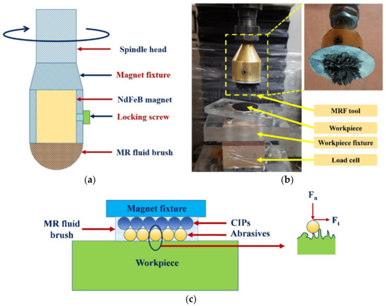
Figure 2.
(a) Schematic of MRF tool, (b) experimental setup, and (c) schematic of MRF processing mechanism.
Figure 3 shows the SEM images of CIPs and boron carbide abrasives. It can be observed from the images that CIPs are spherical in shape, whereas abrasive particles are irregular in shape and sharp. The details of the finishing experiment are provided in Table 3. The machining parameters were selected based on the literature and trial experiments [24]. The number of passes was fixed such that substantial changes in surface roughness could be observed. With a greater number of passes, all the samples converged to a definite surface roughness and it became difficult to evaluate the effect of different process parameters. Therefore, 5 passes were selected to evaluate the intermediate finishing results. Then, based on the evaluation of input process parameters, an optimal combination of process parameters was obtained. The final finishing is carried out with this parameter setting to produce a mirror-like surface with no or negligible surface damage.
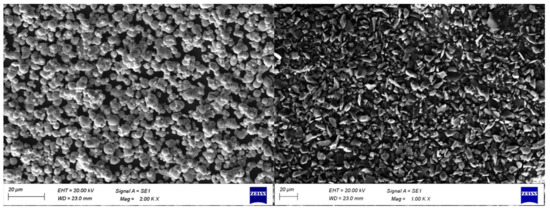
Figure 3.
SEM images of CIPs (left) and boron carbide abrasive particles (right).
Table 3.
The details of the finishing experiment.
Table 4 lists the experimental plan and response parameters. The surface roughness, forces, and hardness changed after chemical treatment. Abrasive particles were indented into the workpiece surface as the MR fluid was pressed over the workpiece. The normal cutting force measures the indentation of the abrasive particles. The surface peaks of the workpiece were sheared away by abrasion due to the rotation of the tool. This is related to tangential cutting force. The combination of both normal and tangential cutting forces is responsible for effective material removal from the workpiece surface [25].
Table 4.
Experimental plan and response parameters.
3. Results and Discussion
3.1. Microstructure of the As-Plated Surface
The morphology of the electroless nickel-plated surface is shown in Figure 4. It can be seen from the SEM image that the appearance of plating is uniform and homogenous. The texture of the plated surface is wavy and has bigger cells. However, isolated white impurities are observed on the surface that can be related to organic contaminants present in the nickel–phosphorus bath. During the electroless plating, these contaminants were deposited on the surface at scattered locations.
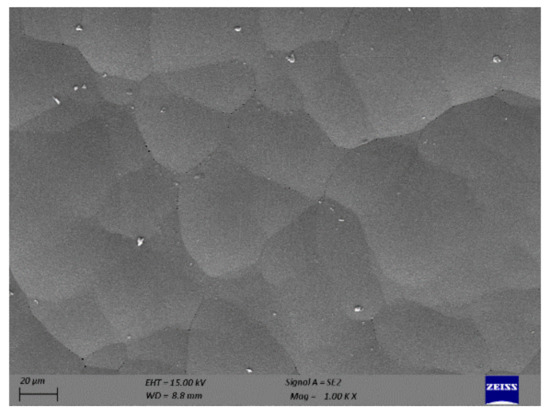
Figure 4.
SEM image of as-plated surface.
Energy dispersive X-ray spectroscopy (EDS) area mapping was carried out on the as-plated surface to understand the distribution of plated elements, and the spot analysis was performed to ascertain the concentration of the major and minor elements. Figure 5 shows the elemental area mapping and spot analysis of the as-plated surface. The weight percentages of nickel and phosphorus were found to be approximately 91% and 9%, respectively. The phosphorus content in the plated surface was at a medium level, which suggests that this surface has reasonable hardness and better corrosion resistant.
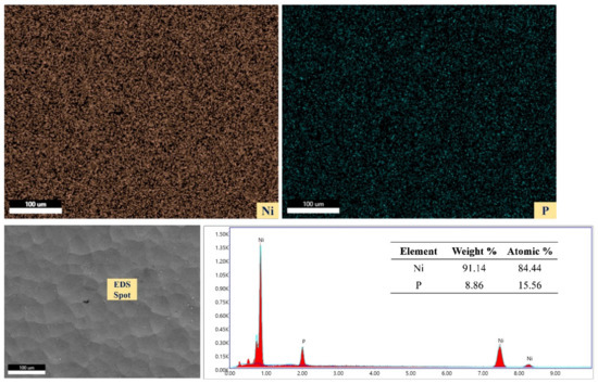
Figure 5.
Elemental area mapping and spot analysis of as-plated surface.
The topography of the as-plated surface is shown in Figure 6. The average areal surface roughness (Sa) of the surface was found to be 960 nm. The surface is rough and has an uneven distribution of peaks and valleys. The surface roughness of the plated surface is directly related to the constituents of the nickel bath during the electroless plating process.
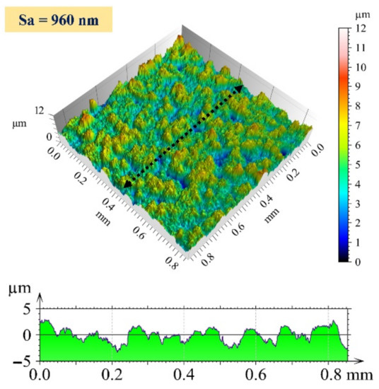
Figure 6.
Three-dimensional surface profile and 2D profile curve (along the marked line in 3D image) of as-plated surface.
3.2. Characterization of Chemically Treated Surface
During wet chemical treatment, the surface chemistry changed owing to different chemical reactions taking place between the chemicals and the surface. The chemical reaction took place by diffusion of chemicals on the surface, redox (oxidation–reduction) reaction between the chemical and workpiece surface, and by-product diffusion. Figure 7a shows a schematic of the series of reactions taking place during chemical treatment. Figure 7b shows a schematic of the chemical reaction of H2O2 and HF with the workpiece surface. A passivation layer was formed during the interaction of the plated surface with the diluted H2O2 and HF. The oxides were formed when the surface interacted with H2O2. The oxidation–reduction (redox) reactions are provided below:
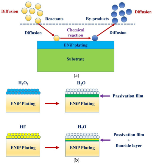
Figure 7.
(a) Schematic of series of reactions taking place during chemical treatment, and (b) schematic of chemical treatment mechanism in hydrogen peroxide (H2O2) and hydrofluoric acid (HF).
As the HF is very corrosive, it is necessary to ensure that the chemical should not remove the whole nickel plating from the surface during treatment. Therefore, concentration of HF was kept low to protect the plating on the substrate even though nickel has very high resistance to corrosion. During chemical treatment with diluted HF, a combination of passivation film and the fluoride layer was formed. HF is considered a weak acid when diluted in water. As a result, the solution had intact HF molecules and different ions of H+, HF2−, and F− [26]. There was no penetration and scattering with the F− ions alone, whereas H+ ions attacked and penetrated the surface. A mix of H+ and F- ions penetrated and spread beneath the chemically reacted surface. There was a chance of the formation of pores owing to pitting corrosion. It is believed that redox reactions take place within the broken small areas at different locations within the passivation film. These passivation films are formed due to the formation of different nickel oxides. The silver colour of the coated surface is likely to change to grey/black with the formation of the oxide layer and the pores. As the chemical treatment was performed at room temperature, the effect of temperature on the chemical reaction was neglected. Equations (4)–(7) show the reactions between the HF and nickel–phosphorous plating.
The SEM images of chemically treated surfaces with 15% H2O2 are shown in Figure 8. It can be clearly seen from Figure 8a that the reaction of H2O2 results in the formation of pits. Moreover, deposition of by-products was also observed when exposure was carried out for 10 min. These are similar to islands or nodules [27]. As the chemical reaction time increased, these deposited by-products were removed by the chemicals and the number of pits and their size increased (Figure 8b). After 30 min of treatment, these deposits were almost gone, but bigger pits could be seen (Figure 8c). Using image processing software ImageJ, it is found that the average size of pits after chemical treatment of 20 and 30 min was 0.65 µm and 2.38 µm, respectively.
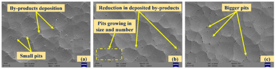
Figure 8.
SEM images of chemically treated surfaces with 15% hydrogen peroxide ((a–c): exposure times of 10, 20, and 30 min).
At lower magnification, the change in the microstructure of the chemically treated surface is not differentiable for HF treatment. However, the detailed features on the surfaces are observed at higher magnification. A lower concentration of HF is less likely to generate higher by-products. Figure 9a,b shows that the surface treated with 1% HF for 10 min and 20 min where scattered deposition with pores around the grain boundaries was observed. After the 30 min chemical treatment duration (Figure 9c), the surface was relatively smooth with the removal of deposited by-products but ridge-kind features were observed. The nickel–plated amorphous structure was easily etched by HF, whereas the crystalline structure had high etch resistance.
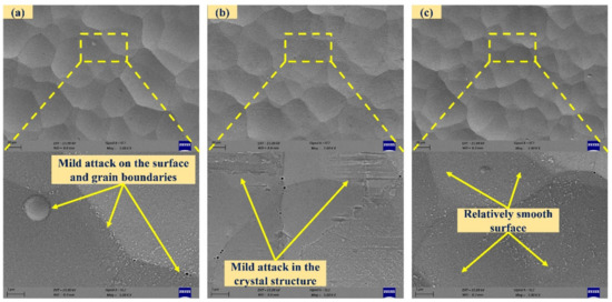
Figure 9.
SEM images of chemically treated surfaces with 1% hydrofluoric acid ((a–c): exposure times of 10, 20, and 30 min).
The SEM images of chemically treated surfaces with 5% HF are shown in Figure 10. A higher concentration of HF is likely to attack the surface aggressively. In the surface with 5% HF for 10 min duration, shallow potholes, scattered deposition with pores and intergranular attack around the boundaries were observed. After 20 min, aggressive attack on the plated surface was observed. Finally, the surface accumulated pits when treated for 30 min. The electroless deposit had a non-uniform distribution of phosphorus in the depth and in plane directions. As soon as the plated surface was dipped in the high concentration of HF, the acid attacked the region with lower phosphorous content. Due to the formation of a passivation layer, the acid attack translated into depth direction, resulting in pits. At a higher processing time, the attack was intense at some locations, and there was a possibility of the formation of pores in the vicinity.
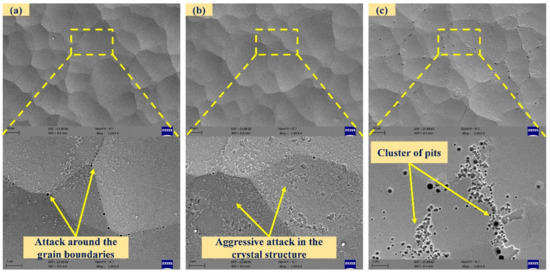
Figure 10.
SEM images of chemically treated surfaces with 5% hydrofluoric acid ((a–c): exposure times of 10, 20, and 30 min).
The XPS results were analysed for the composition of the as-plated and chemically treated surfaces (with H2O2 and HF). Figure 11a presents the XPS spectra (Ni 2p, P 2p, and O 1s) of the as-plated surface. In the Ni 2p spectrum, the peak located at 851 eV indicates the presence of nickel metal [28]. The peaks observed at 852.2 eV and 868.2 eV indicate NiP 2p3/2 and Ni 2p1/2, respectively [29,30]. The other peak at 854 eV corresponds to NiO 2p3/2 [31]. The satellite peak was observed at 870.5 eV. In the P 2p spectrum, peaks at 127.6 eV, 128.4 eV, and 132 eV correspond to P 2p3/2, NiP 2p1/2, and P 2p3/2, respectively. The satellite peaks appeared at 135.4 eV and 138.1 eV. In O 1s spectrum, peaks at 530 eV and 531.6 eV correspond to surface oxidation [32].
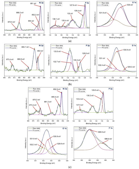
Figure 11.
XPS spectra of (a) as-plated and chemically surfaces treated with (b) H2O2 and (c) HF.
Figure 11b presents the XPS spectra (Ni 2p, P 2p, and O 1s) of the surface chemically treated with H2O2. In the Ni 2p spectrum, the peaks observed at 853 eV and 855.7 eV indicate Ni 2p3/2 and Ni2O3 2p3/2, respectively [19]. The other peaks at 860.6 eV and 873.4 eV correspond to NiO 2p3/2 and Ni2O3 2p1/2, respectively [19,31]. In the P 2p spectrum, peaks at 129.6 eV, 130.4 eV, and 133.5 eV correspond to P 2p3/2, NiP 2p1/2, and P3+ 2p3/2, respectively. The peak at 132.7 eV corresponds to P 2p1/2. In the O 1s spectrum, peaks at 530.9 eV, 531 eV, and 532.4 eV correspond to NiO, Ni2O3, and P2O3, respectively. The lower peak intensities of Ni2O3 and P2O3 indicate low oxygen content. The satellite peak appeared at 529.2 eV.
Figure 11c presents the XPS spectra (Ni 2p, P 2p, O 1s, and F 1s) of the surface chemically treated with HF. In the Ni 2p spectra, the peak observed at 852.9 eV indicates Ni 2p3/2 [33]. The peaks observed at 855.4 eV and 861.2 eV indicate Ni2+ 2p3/2 [31]. The other peaks at 870.2 eV and 873.2 eV correspond to Ni2+ 2p3/2 and NiP 2p1/2, respectively. In the P 2p spectrum, peaks at 129.5 eV, 130.2 eV, and 133.4 eV correspond to P3+ 2p3/2, NiP 2p1/2, and P5+ 2p3/2, respectively [33]. The satellite peak appeared at 137.5 eV. In the O 1s spectrum, peaks at 530.9 eV and 532.3 eV correspond to NiO and P2O5, respectively. The peaks at the binding energies of 529.8 eV and 531.8 eV are observed due to hydroxyl groups present on the surface [29]. In the F 1s spectrum, peaks at 686.9 eV and 689.9 eV correspond to PF3 and NiF2, respectively.
The microhardness of the chemically treated surfaces was lower than that of the as-plated surface, as shown in Figure 12. It was observed that the chemical treatment with H2O2 results in a continuous drop in hardness due to the formation of an oxide layer, which is softer than the as-plated surface. Moreover, the size and number of pits also increased with more chemical treatment duration, and it reduced the hardness further. The HF treatment resulted in the formation of both passivation and chemical films and the lowest hardness was observed after 10 min of exposure. In 10 to 20 min of chemical exposure, chemical and passivation films degraded and consequently the hardness increased due to resurfacing of the base material. After 30 min of chemical treatment, the hardness decreased where the chemically treated surface with 1% HF showed higher values owing to a group of pits that developed on the chemically treated surface with 5% HF. The decrease in hardness after 30 min of chemical treatment can be attributed to dissolution nature of nickel and phosphorus in the HF solution. The surface dissolution leads to structural modification of the exposed surface [34]. Moreover, the change in the concentration of nickel and phosphorus affect the mechanical properties of the surface layer [35].
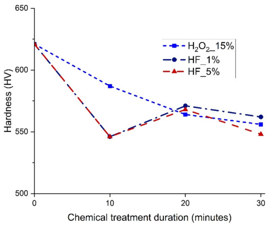
Figure 12.
Microhardness of chemically treated surfaces.
3.3. Surface Roughness
The areal surface roughness of the chemically treated surfaces with 15% H2O2 and 5% HF increased with chemical treatment duration, whereas it decreased with 1% HF, as shown in Figure 13. This can be related to pit formation and aggressive attack by HF at higher concentrations, which deteriorate the surface quality. At lower concentrations of HF, the surface became smoother and the pits were almost negligible. This improved the surface quality and resulted in the lowest surface roughness after 30 min of chemical treatment with 1% HF. The maximum and minimum areal surface roughness achieved after chemical treatment for 30 min with 5% HF and 1% HF, respectively, are shown in Figure 14. The initial areal surface roughness of the plated surface was 960 nm as shown in Figure 6. The maximum roughness observed in the chemical treatment process was 1209 nm, whereas the minimum surface roughness observed in the chemical treatment process was 370 nm.
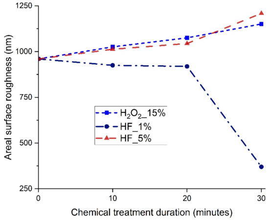
Figure 13.
Areal surface roughness of chemically treated surfaces.
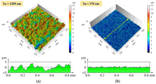
Figure 14.
Three-dimensional surface profile and 2D profile curve (along the marked line in 3D image) for the chemically treated surface at (a) 5% HF and 30 min exposure time and (b) 1% HF and 30 min exposure time.
The two important terms associated with the performance of a finishing process are the finishing rate and the percentage reduction in surface roughness [36]. These terms are calculated as follows:
Figure 15 shows the finishing rate and percentage reduction in surface roughness of as-plated and chemically treated surfaces. The rate of finishing and the percentage reduction in surface roughness for the as-plated surface are 76 nm/min and 79%, respectively. The rate of finishing was higher for all chemically treated surfaces except the chemically treated with 1% HF and for a duration of 30 min. The primary reason for this is the lowest initial surface roughness after the chemical treatment. As the roughness was quite low as compared to other surfaces, this surface had lower peaks, which are more difficult to remove as compared to higher peaks. If the surface is too rough, material removal is easier initially due to sharp and gentle peaks. After that, the subsequent reduction in material removal becomes more difficult as the peaks are flattened and more surface is exposed. All the chemically treated surfaces have a higher percentage reduction in surface roughness when compared with the as-plated surface. These results support the hypothesis that material removal is made easy owing to a chemically modified surface and that a lower final roughness can be achieved on a chemically treated surface.
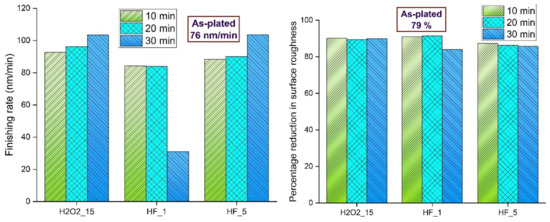
Figure 15.
Finishing rate and percentage reduction in areal surface roughness of as-plated and chemically treated surfaces.
The two major finishing forces in MRF are the normal and tangential forces, which are responsible for the indentation of the active workpiece and the removal of material from the workpiece surface, respectively. The normal force acting on the interface by a single active abrasive is the sum of magnetic force, gravitational force, and centrifugal force. The tangential force acting on the interface is a shear force. The normal and tangential forces during MRF of as-plated and chemically treated surfaces are shown in Figure 16.
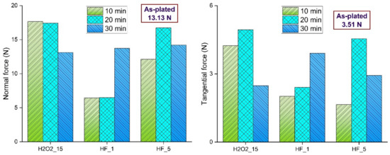
Figure 16.
Normal and tangential forces during MRF of as-plated and chemically treated surfaces.
These forces are mainly influenced by hardness, surface roughness, and surface defects. For surfaces treated with 15% H2O2, normal force decreased with chemical treatment duration due to a decrease in hardness. As the surface roughness increased, the tangential force increased and then decreased owing to bigger pits. For surfaces treated with 1% HF, normal force and tangential forces had similar trends, as both forces increased with chemical treatment duration. This can be attributed to lower hardness, which allows abrasive particles to indent deeper easily and remove more material. For surfaces treated with 5% HF, normal and tangential forces have similar trends. For this, the trend follows the pattern of hardness. More clusters of pits were observed at high surface roughness, which resulted in low tangential force at a chemical treatment duration of 30 min.
The final finishing was carried out on the chemically treated surface (1% HF for 30 min), and the areal surface was reduced to 10 nm. An actual photograph of the as-plated and nanofinished surface is shown in Figure 17a. The 3D surface profile of the nanofinished surface is shown in Figure 17b. Furthermore, the SEM micrograph and elemental area mapping of the finished surface are shown in Figure 17c. It can clearly be seen that the finished surface is smooth, with some pits owing to the electroless plating process.
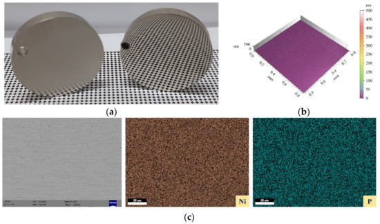
Figure 17.
(a) Actual photograph of as-plated and nano-finished surfaces, (b) 3D surface profile of finished surface, and (c) SEM micrograph and elemental area mapping of finished surface.
The findings of this study were compared to previous studies on the finishing of chemically treated surfaces or chemically assisted finishing. It was observed that chemically assisted shape adaptive grinding (SAG) results in effective and efficient material removal [22]. This can be attributed to combined mechanical action and chemical etching. Moreover, it was concluded that better material removal efficiency and surface quality can be obtained by the synergy between mechanical abrasion and chemical reaction.
4. Conclusions
In this work, nickel-plated surfaces were chemically treated using hydrogen peroxide and hydrofluoric acid. The chemically treated surfaces were finished using magnetorheological finishing. The following conclusions were drawn:
- The surface topography of the chemically treated surfaces revealed that the pits are formed and grown in size with an increase in chemical treatment duration with 15% H2O2. The surface chemically treated with 1% HF is relatively smooth having mild reaction. A higher concentration of HF (5%) results in aggressive reaction on the surface and cluster of pits are formed after a chemical treatment duration of 30 min.
- The microhardness of the chemically treated surface decreases after chemical treatment irrespective of chemical and exposure duration. The surface roughness of the chemically treated surfaces increases with 15% H2O2 and 5% HF whereas it decreases with 1% HF. This is related to the formation of pits and surface film. The minimum and maximum surface roughness after chemical treatment is achieved on surfaces chemically treated with 1% HF for 30 min and 5% HF for 30 min, respectively.
- The percentage reduction in surface roughness for chemically treated surfaces after MRF is higher than the same for an as-plated surface. The finishing rate is lowest for surface treated with 1% HF for 30 min. The drastic reduction in surface roughness after chemical treatment is the sole reason for this. All other surfaces have a higher finishing rate when compared with an as-plated surface.
- The normal and tangential forces are mainly dependent on hardness and surface roughness of the surfaces. Moreover, the formation of pits, deposition and intergranular attack also affect these finishing forces.
- A minimum roughness of 10 nm is achieved on a surface chemically treated with 1% HF for a duration of 30 min. There is a reduction of 99% in surface roughness in a two-step process (chemical treatment and MRF). It can be concluded that material removal becomes easy after chemical treatment.
Author Contributions
Conceptualization, visualization, M.K., T.B., S.R. and A.S.; methodology, validation, formal analysis, investigation, writing—original draft preparation, M.K., T.B. and S.R.; writing—review and editing, M.K. and A.S.; supervision, resources, project administration, A.S. All authors have read and agreed to the published version of the manuscript.
Funding
This research was funded by Space Applications Centre (SAC) of the Indian Space Research Organization (ISRO).
Institutional Review Board Statement
Not applicable.
Informed Consent Statement
Not applicable.
Data Availability Statement
Not applicable.
Acknowledgments
The authors thank ENP Techno Engineers, Ahmedabad, India, for their help with the electroless nickel plating.
Conflicts of Interest
The authors declare no conflict of interest.
References
- Loto, C.A. Electroless nickel plating–a review. Silicon 2016, 8, 177–186. [Google Scholar] [CrossRef]
- Sudagar, J.; Lian, J.; Sha, W. Electroless nickel, alloy, composite and nano coatings–A critical review. J. Alloys Compd. 2013, 571, 183–204. [Google Scholar] [CrossRef]
- Vitry, V.; Sens, A.; Delaunois, F. Comparison of various electroless nickel coatings on steel: Structure, hardness and abrasion resistance. Mater. Sci. Forum 2014, 783–786, 1405–1413. [Google Scholar] [CrossRef]
- Namba, Y.; Shimomura, T.; Fushiki, A.; Beaucamp, A.; Inasaki, I.; Kunieda, H.; Ogasaka, Y.; Yamashita, K. Ultra-precision polishing of electroless nickel molding dies for shorter wavelength applications. CIRP Ann. 2008, 57, 337–340. [Google Scholar] [CrossRef]
- Kumar, Y.; Singh, H. Chemomechanical magnetorheological finishing: Process mechanism, research trends, challenges and opportunities in surface finishing. J. Micromanuf. 2021, 5(2), 193–206. [Google Scholar] [CrossRef]
- Ji, F.; Xu, M.; Wang, C.; Li, X.; Gao, W.; Zhang, Y.; Wang, B.; Tang, G.; Yue, X. The magnetorheological finishing (MRF) of potassium dihydrogen phosphate (KDP) crystal with Fe3O4 nanoparticles. Nanoscale Res. Lett. 2016, 11, 79. [Google Scholar] [CrossRef]
- Sidpara, A.M.; Jain, V.K. Nanofinishing of freeform surfaces of prosthetic knee joint implant. Proc. Inst. Mech. Eng. B J. Eng. Manuf. 2012, 226, 1833–1846. [Google Scholar] [CrossRef]
- Seok, J.; Kim, Y.J.; Jang, K.I.; Min, B.K.; Lee, S.J. A study on the fabrication of curved surfaces using magnetorheological fluid finishing. Int. J. Mach. Tools Manuf. 2007, 47, 2077–2090. [Google Scholar] [CrossRef]
- Jung, B.; Jang, K.I.; Min, B.K.; Lee, S.J.; Seok, J. Magnetorheological finishing process for hard materials using sintered iron-CNT compound abrasives. Int. J. Mach. Tools Manuf. 2009, 49, 407–418. [Google Scholar] [CrossRef]
- Wang, H.; Meng, Y.; Li, Z.; Dong, J.; Cui, H. Steady-State and Dynamic Rheological Properties of a Mineral Oil-Based Ferrofluid. Magnetochemistry 2022, 8, 100. [Google Scholar] [CrossRef]
- Socoliuc, V.; Peddis, D.; Petrenko, V.I.; Avdeev, M.V.; Susan-Resiga, D.; Szabó, T.; Turcu, R.; Tombácz, E.; Vékás, L. Magnetic nanoparticle systems for nanomedicine—A materials science perspective. Magnetochemistry 2020, 6, 2. [Google Scholar] [CrossRef]
- Liu, G.; Li, J.; Zhu, S.; Zhu, X.; Qu, J.; Zhang, X. Experimental and Numerical Analysis of the Assisted Abrasive Flow of Magnetic Particles on the Polishing of Fuel Injection Nozzles. Magnetochemistry 2022, 8, 35. [Google Scholar] [CrossRef]
- Luo, H.; Guo, M.; Yin, S.; Chen, F.; Huang, S.; Lu, A.; Guo, Y. An atomic-scale and high efficiency finishing method of zirconia ceramics by using magnetorheological finishing. Appl. Surf. Sci. 2018, 444, 569–577. [Google Scholar] [CrossRef]
- Miao, C.; Lambropoulos, J.C.; Jacobs, S.D. Process parameter effects on material removal in magnetorheological finishing of borosilicate glass. Appl. Opt. 2010, 49, 1951–1963. [Google Scholar] [CrossRef]
- Shafrir, S.N.; Lambropoulos, J.C.; Jacobs, S.D. A magnetorheological polishing-based approach for studying precision microground surfaces of tungsten carbides. Precis. Eng. 2007, 31, 83–93. [Google Scholar] [CrossRef]
- Khan, D.A.; Jha, S. Synthesis of polishing fluid and novel approach for nanofinishing of copper using ball-end magnetorheological finishing process. Mater. Manuf. Process. 2018, 33, 1150–1159. [Google Scholar] [CrossRef]
- Mu, Y.; Zhong, M.; Rushing, K.J.; Li, Y.; Shipp, D.A. Benzotriazole as a passivating agent during chemical mechanical planarization of Ni–P alloy substrates. Appl. Surf. Sci. 2014, 315, 190–195. [Google Scholar] [CrossRef]
- Chu, C.L.; Wang, R.M.; Hu, T.; Yin, L.H.; Pu, Y.P.; Lin, P.H.; Wu, S.L.; Chung, C.Y.; Yeung, K.W.K.; Chu, P.K. Surface structure and biomedical properties of chemically polished and electropolished NiTi shape memory alloys. Mater. Sci. Eng. C 2008, 28, 1430–1434. [Google Scholar] [CrossRef]
- Zhang, Z.; Liao, L.; Wang, X.; Xie, W.; Guo, D. Development of a novel chemical mechanical polishing slurry and its polishing mechanisms on a nickel alloy. Appl. Surf. Sci. 2020, 506, 144670. [Google Scholar] [CrossRef]
- Xu, C.; Peng, X.; Liu, J.; Hu, H.; Lai, T.; Yang, Q.; Xiong, Y. A High Efficiency and Precision Smoothing Polishing Method for NiP Coating of Metal Mirror. Micromachines 2022, 13, 1171. [Google Scholar] [CrossRef]
- Hu, H.; Xu, C.; Lai, T.; Yang, Q.; Peng, X.; Liu, J.; Xiong, Y.; Qiu, J. Sub-Nanometer Accuracy Combination Processing Technology for Nickel–Phosphorus Modified Surfaces Based on Aluminum Reflector Mirror. Micromachines 2022, 13, 560. [Google Scholar] [CrossRef]
- Ghosh, G.; Sidpara, A.; Bandyopadhyay, P.P. High efficiency chemical assisted nanofinishing of HVOF sprayed WC-Co coating. Surf. Coat. Technol. 2018, 334, 204–214. [Google Scholar] [CrossRef]
- Ghosh, G.; Kumar, M.; Sidpara, A.M.; Bandyopadhyay, P.P. Tribological aspects of different machining processes. In Machining and Tribology, 1st ed.; Pramanik, A., Ed.; Elsevier: Amsterdam, The Netherlands, 2022; pp. 213–238. [Google Scholar] [CrossRef]
- Ghosh, G.; Sidpara, A.; Bandyopadhyay, P.P. Magnetorheological finishing of WC-Co coating using iron-B4C-CNT composite abrasives. Tribol. Int. 2021, 155, 106807. [Google Scholar] [CrossRef]
- Kumar, M.; Sidpara, A.M.; Racherla, V. Finishing of OFHC copper using fluid filled open-cell porous flexible abrasive impregnated tools. Proc. Inst. Mech. Eng. B J. Eng. Manuf. 2022, 1879. [Google Scholar] [CrossRef]
- Park, H.; Cho, J.H.; Jung, J.H.; Duy, P.P.; Le, A.H.T.; Yi, J. A review of wet chemical etching of glasses in hydrofluoric acid based solution for thin film silicon solar cell application. Curr. Photovolt. Res. 2017, 5, 75–82. [Google Scholar] [CrossRef]
- Lin, J.D.; Chou, C.T. The influence of phosphorus content on the microstructure and specific capacitance of etched electroless Ni-P coatings. Surf. Coat. Technol. 2019, 368, 126–137. [Google Scholar] [CrossRef]
- Skibińska, K.; Kutyła, D.; Yang, X.; Krause, L.; Marzec, M.M.; Żabiński, P. Rhodium-decorated nanoconical nickel electrode synthesis and characterization as an electrochemical active cathodic material for hydrogen production. Appl. Surf. Sci. 2022, 592, 153326. [Google Scholar] [CrossRef]
- Qi, Z.; Lee, W. XPS study of CMP mechanisms of NiP coating for hard disk drive substrates. Tribol. Int. 2010, 43, 810–814. [Google Scholar] [CrossRef]
- Zhou, Y.; Zhang, Y.; Xu, X.; Zhao, S.; Guo, Z.; Wu, K.H.; Tan, C.; Wang, Z. Bimetallic metal-organic framework derived metal-carbon hybrid for efficient reversible oxygen electrocatalysis. Front. Chem. 2019, 7, 747. [Google Scholar] [CrossRef]
- Biesinger, M.C.; Payne, B.P.; Lau, L.W.; Gerson, A.; Smart, R.S.C. X-ray photoelectron spectroscopic chemical state quantification of mixed nickel metal, oxide and hydroxide systems. Surf. Interface Anal. 2009, 41, 324–332. [Google Scholar] [CrossRef]
- Vivet, L.; Joudrier, A.L.; Bouttemy, M.; Vigneron, J.; Tan, K.L.; Morelle, J.M.; Etcheberry, A.; Chalumeau, L. Wettability and XPS analyses of nickel–phosphorus surfaces after plasma treatment: An efficient approach for surface qualification in mechatronic processes. Appl. Surf. Sci. 2013, 274, 71–78. [Google Scholar] [CrossRef]
- Zhang, H.; Lu, Y.; Gu, C.D.; Wang, X.L.; Tu, J.P. Ionothermal synthesis and lithium storage performance of core/shell structured amorphous@ crystalline Ni–P nanoparticles. CrystEngComm 2012, 14, 7942–7950. [Google Scholar] [CrossRef]
- Zheng, Z.; Zu, X.; Jiang, X.; Xiang, X.; Huang, J.; Zhou, X.; Li, C.; Zheng, W.; Li, L. Effect of HF etching on the surface quality and laser-induced damage of fused silica. Opt. Laser Technol. 2012, 44, 1039–1042. [Google Scholar] [CrossRef]
- Li, X.; Jiang, L.; Li, L.; Yan, Y. Effects of HF etching on nanoindentation response of ion-exchanged aluminosilicate float glass on air and tin sides. J. Mater. Sci. 2017, 52, 4367–4377. [Google Scholar] [CrossRef]
- Kumar, M.; Sidpara, A.M.; Racherla, V. Surface finishing of aluminium 6061 using fabricated flexible abrasive tool. Mater. Today Commun. 2022, 33, 104614. [Google Scholar] [CrossRef]
Publisher’s Note: MDPI stays neutral with regard to jurisdictional claims in published maps and institutional affiliations. |
© 2022 by the authors. Licensee MDPI, Basel, Switzerland. This article is an open access article distributed under the terms and conditions of the Creative Commons Attribution (CC BY) license (https://creativecommons.org/licenses/by/4.0/).