Abstract
The present study deals with the performance of an U-shaped oscillating water column device under the action of oblique incident waves. To solve the associated boundary value problem, the dual boundary element method (DBEM) is used. Various physical parameters associated with the U-shaped OWC device, such as the radiation susceptance and conductance coefficients, and the hydrodynamic efficiency, are analyzed for a wide range of wave and structural parameters. The study reveals that the resonance in the efficiency curve occurs for smaller values of wavenumber with an increase in chamber length, submergence depth of the front wall and opening duct, and width of the opening duct. It is observed that with appropriate combinations of the angle of incidence and incident wavenumber, more than efficiency in the U-shaped OWC device can be achieved.
1. Introduction
Renewable energy has become an essential factor in the fields of environmental sustainability and energy policy, and it also evolved as an alternative to fossil and nuclear energy sources due to their non-polluting nature, and plentiful energy harvested from self-renewing resources such as the sun, wind, wave, etc. In this regard, renewable energy will features prominently in the upcoming future. Out of numerous sources of renewable energy, wave energy has an enormous potential to become the ultimate source of energy and convert it into electricity. Among the myriad wave power generation technology, the concept of an oscillating water column device (OWC-WEC) is well established due to its simple working mechanism. The mathematical modeling of these OWC devices was started since 1980 by several researchers across the world. Ref. [1] used the Galerkin method to investigate the hydrodynamic performance of an OWC device under the assumption of linear water wave theory. In this study, various important parameters related to the efficiency of the OWC devices, such as the radiation susceptance and radiation conductance, volume flux inside the chamber, and maximum efficiency of the OWC, were analyzed for various values of shape parameters associated with the device. Further, two different resonance mechanisms were illustrated to achieve maximum efficiency in the OWC device. Ref. [2] analyzed the effect of various geometries of the front wall of the device chamber on the efficiency of an OWC-device using a level-set immersed boundary method. It was observed that the pressure variation across the turbine is less for the case of sloshing frequency as compared with the resonating frequency. As a consequence, the efficiency of the OWC device doesn’t depend significantly on the sloshing frequencies. Ref. [3] used the CFD-technique to study the hydrodynamic performance of an onshore OWC device. It was concluded that the length and height of the device chamber and pneumatic turbine characteristics significantly enhance the hydrodynamic performance of an OWC device. Ref. [4] used both the eigenfunction expansion method and the boundary element method to investigate the performance of an OWC device placed over the stepped type bottom. It was reported that the existence of stepped bottom outside of the device chamber significantly affects the efficiency of an OWC device. Ref. [5] studied the hydrodynamic performance of an “U”-shape OWC device in time-domain using the Monte Carlo simulations technique. It was reported that the frequency spectrum and the peak period of the wave pressure spectrum play a significant role in enhancing the performance of an U-OWC device. Ref. [6] analyzed the hydrodynamic performance of an OWC device under the action of oblique incident waves experimentally. It was observed that the performance of an OWC device varies proportionally to the direction angle of the incident wave. Ref. [7] used a higher-order boundary element method (BEM) to investigate the performance of an OWC device placed over a sloping bed. It was found that the shape parameters of an OWC device, non-linearity of the incident waves, and slopes of the bottom profile play a vital role on the efficiency of the OWC-device. Refs. [8,9] extended the work of [4] by considering the dual-chamber placed over the stepped and uniform bottom. It was observed that the existence of bottom steps in front of the OWC device enhances the hydrodynamic performance of the OWC device. Further, the dual-chamber OWC can effectively work in wider frequencies of incoming waves as compared to the OWC device having a single chamber. Ref. [10] studied the performance of an OWC device experimentally under the random wave’s environment and showed that the reflection coefficient increases with an increase in submergence depth of the front wall. Ref. [11] investigated the performance of an array of OWC devices experimentally under the action of oblique incident waves. It was found that the development of vortices in the neighborhood of the front wall reduces the amplitude of the free surface elevation. Further, the relative capture width of the OWC device decreases with an increase in the obliqueness of the incident waves. Ref. [12] used Maximum Power Point Tracking algorithm and wave-to-wave control algorithm to study the performance of a breakwater-integrated U-shaped OWC device under the action of irregular incident waves. It was found that in swell-dominated sea states, the turbine rotational speed significantly enhances the performance of an U-OWC device. Moreover, in the wind-dominated sea state, resonance conditions play a crucial role in increasing the efficiency of an U-OWC device. Ref. [13] developed an experimental model to study the hydrodynamic performance of an OWC device placed over the undulated seabed. It was reported that the performance of an U-shaped OWC device is better than other conventional OWC devices. Moreover, the efficiency of an U-shaped OWC device placed over the sloping bottom is higher than the other proposed models of the OWC-devices. Ref. [14] analyzed the hydrodynamic performance of a rectangular OWC device placed over the stepped bottom numerically and experimentally under the irregular incident waves, and it was found that the incident wave frequency and the turbine damping coefficient play a vital role to enhance the efficiency of an OWC device as compared to the incident wave height. Ref. [15] used nonlinear stochastic analysis to investigate the performance of an U-shaped OWC device. It was shown that nonlinear stochastic analysis is times more computationally efficient than the Monte Carlo simulations. Ref. [16] performed model tests to study the effect of harbor walls on the hydrodynamic efficiency of an OWC device. It was concluded that: (i) harbor wall plays a crucial role in enhancing the performance of an OWC device, and (ii) the natural frequency of an OWC device can be determined by the resonating length of the harbor walls. On the other hand, the natural frequency of an OWC device does not depend on the inclination of the harbor walls. Ref. [17] used a semi-analytical approach to study the performance of an U-OWC arrays under the action of regular and irregular incident waves. In this study, the following conclusions were obtained: (i) under the action of regular incident waves, the performance of the U-OWC significantly enhanced by the hydrodynamic parameters, (ii) the pneumatic power available to the turbine is more for the isolated U-OWC than the case when the same is present in an array, and (iii) in random waves environment, the chamber width significantly increases the average power output of the OWC device. Recently, ref. [18] developed a physics-based simulation model to analyze the efficiency and structural durability of a fixed OWC device in random ocean waves. It was found that the hydrodynamic performance of the OWC device depends on the rotational speed of the turbine and the submergence depth of the OWC device. Ref. [19] used a coupled eigenfunction expansion method and BEM method to study the performance of an OWC device placed over an undulated sea bed. It was reported that (i) for long waves, a protrusion type bed profile enhances the performance of an OWC device, (ii) for incident waves having intermediate and short wavelengths, the depression type bed profile is appropriate to enhance the efficiency of the OWC device, and (iii) the number of ripples and ripple amplitudes of the sinusoidally varying seabed play a significant role to enhance the performance of the OWC device.
In all the research mentioned earlier, the solution methodology is either based on a semi-analytical approach or numerical methods such as CFD and BEM, etc. The boundary element method is an efficacious tool to analyze the behavior of the mechanical system and the engineering problems due to easy numerical modeling and the reduction of unknowns by order one [20]. However, the conventional BEM has rank deficiency issues of influence matrices for problems having degenerate boundaries. In this regard, dual BEM plays a vital role in resolving the aforementioned rank deficiency problems (see [21] for details). Ref. [22] developed a dual boundary element method to solve the problem of oblique incident wave interaction with a thin impermeable vertical barrier. The computational procedure of the kernels present in the hypersingular integral equations was provided for the singular element cases. Using the dual boundary element method, ref. [23] studied the normal gravity waves scattering by a thin submerged barrier of rigid, permeable, and absorbing nature. It was found that the run time for the dual boundary element method is significantly less than the multi-domain boundary element method. Ref. [21] demonstrated that the degenerate boundary value problem that arises in the presence of a thick barrier could easily be solved using the dual boundary element method (DBEM). Ref. [24] analyzed water waves scattering by an array of inverted trapezoidal porous boxes using the DBEM solution method.
In the present study, the hydrodynamic parameters associated with the performance of an U-shaped OWC device, such as the radiation conductance and radiation susceptance coefficients, and the efficiency of the OWC device, are studied for a variety of waves and structural parameters. The present model is based on the linearized water wave theory and therefore, the nonlinear phenomena such as the wave breaking and the steep amplitude of the wave inside the chamber, etc., are not incorporated in the present model. However, the present linearized wave-structure interaction theory is very helpful to understand the working mechanism of the OWC devices and will also provide fruitful results of various parameters associated with the performance of the devices [1,14]. To solve the associated boundary value problem, the dual boundary element method is used. The overall structure of the paper is the following. In Section 2, the detailed mathematical formulation associated with the physical problem is provided. Section 3 contains the detailed solution methodology based on the dual boundary element method. In Section 4, the expressions for various physical parameters associated with the performance of the U-shaped OWC device are provided. Section 5 contains various results and related detailed discussions. Finally, the summary of the present study is provided in Section 6.
2. Mathematical Formulation
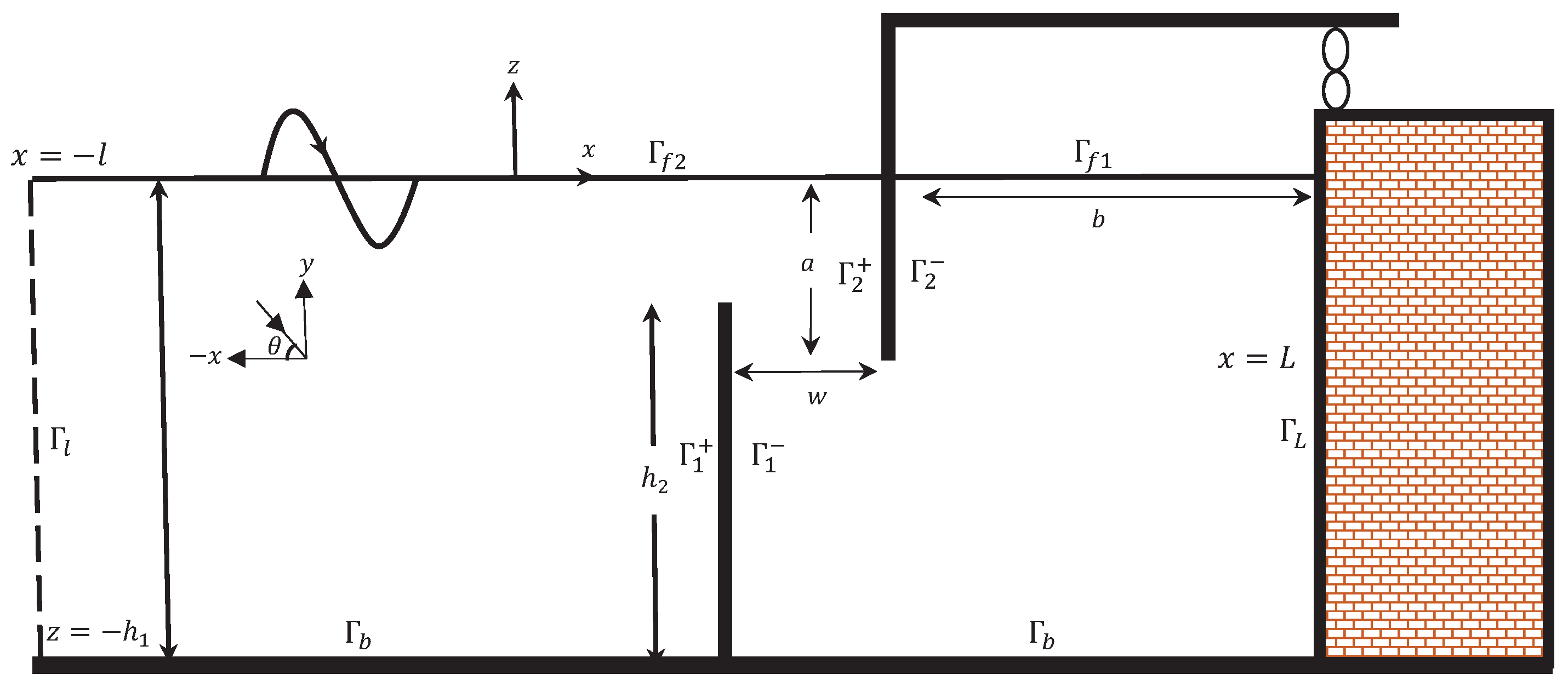
The present section yields the mathematical formulation of an U-shaped OWC device under the action of oblique incident waves. The schematic diagram of the physical problem is given in Figure 1. For the sake of mathematical modeling, a three-dimensional Cartesian coordinate system is taken in which the -plane is horizontal, and the z-axis is considered in the vertical direction. The U-OWC device consists of a duct and chamber as seen in Figure 1. Further, the U-OWC device is placed over the uniform bottom bed having depth and extended infinitely in the y-direction. In reality, this means that the dimension of the OWC device in the y-direction is large compared to the incident wavelength. The submergence depth of the opening duct and rear wall of the duct are and a respectively, and the width of the duct is w. Further, the rear wall of the chamber is located at , and the length of the chamber is b. The Wells turbine is placed at the top of the rear side of the U-OWC device. In the presence of the U-OWC device, the free surface is divided into two parts in the -plane: (i) internal free surface , i.e., the free surface inside the OWC chamber, and (ii) external free surface , i.e., the free surface outside the OWC device chamber. Further, the bottom boundary of the OWC device is denoted by . To close the domain, one vertical auxiliary boundary is considered at . For the modeling purpose, the water and the related motion are assumed to be inviscid, incompressible, and irrotational in nature. Further, the water waves are assumed to be time-harmonic in nature with the circular frequency .
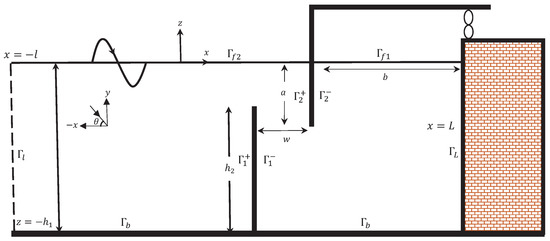
Figure 1.
Vertical cross section of an U-shaped OWC device.
These assumptions guarantee the existence of the velocity potential of the form with . Therefore, satisfies the Helmholtz equation
The boundary condition at the mean free surface is given by (see [19] for details)
where with g being the gravitational acceleration and represents the normal derivative. Now, the boundary condition on the rigid bottom is given by
Similarly, the boundary condition on impenetrable boundaries is given by
Now, the total velocity potential is decomposed into two parts as follows (see [1])
where and represent the scattered and radiated velocity potentials respectively. Further, the scattered velocity potential can be decomposed into incident potential and diffracted potential . Now, and satisfy Equations (1)–(4) with Equation (2) will be modified into the following form
where for the radiation potential , and for the scattered potential . Finally, the far-field boundary conditions are given by
where with being the positive real root of the dispersion relation . Further, , and are the coefficients associated with the amplitude of the reflected and radiated waves at respectively. To close the domain, an auxiliary boundary is taken at , and this auxiliary boundary is located sufficiently far away from the OWC device. Therefore, the far-field boundary conditions (7) hold on . In the boundary element method, the following modified form of the far-field boundary conditions (7) are used
3. Numerical Solutions Based on DBEM
In this section, the dual boundary element method (DBEM) is used to solve the BVP (boundary value problem) formulated in Section 2. In the DBEM based solution technique, the BVP is transformed into a system of integral equations using appropriate Green’s function. Using Green’s third identity on the velocity potentials and the free-space Green’s function over the domain bounded by , the following integral equation is obtained as
where
It is to be noted that the free-space Green’s function as in (9) satisfies the governing equation
and takes the form
where is the Dirac-delta function, is modified zeroth-order Hankel function of the first kind and r is the distance between the field point and the source point . Taking the normal derivative in Equation (9), we get
where
When the field point , Equations (9) and (13) can be written as
Here, , , and are termed as the Riemann principal value, Cauchy principal value, and Hadamard principal value respectively.
In Equations (15) and (16), the total boundary can be written as with represent the non-degenerate boundary and and are the degenerate boundaries. Further, the non-degenerate boundary composed of . Now, a system of four integral equations are obtained from Equations (15) and (16) by considering , and . These system of integral equations are converted into system of linear algebraic equations and solved to determine the required unknowns. The detailed procedure is provided in the Appendix A.
4. Various Parameters Associated with U-Shaped OWC Device
Here, the expressions for various parameters associated with the performance and efficiency of the U-shaped OWC device discussed in Section 2 are provided. The average energy flux per unit length across a vertical cross-section normal to the x-direction is given by (see [19] for details)
The volume flow rate q across the internal free surface can be expressed as
with and being the volume flow rate across the internal free surface associated with the scattering and radiation problems respectively. Now, the volume flux due to the radiation potential can be decomposed into real and imaginary parts (see [1] for details) as the following
where and are termed as the radiation susceptance and radiation conductance parameters respectively. To obtain an explicit expression for the parameter , Green’s second identity is applied on and its complex conjugate over the domain bounded by . Summing up the contributions from all the boundaries, we get
Similarly, the expression for the scattered volume flux can be written as
Using Equations (17), (20) and (21), the relation between and is expressed as the following
The average power absorbed W per unit width of the pressure distribution is given by (see [19] for details)
Assuming linear relationship between the volume flux q and the pressure across the turbine p, we get
where ∧ is a real control parameter depending on turbine characteristics. Substituting (24) into (23) and using relations (18) and (19), we get
Now, the efficiency of the OWC device is given by (using (22) and (25))
Using (26), the maximum efficiency is expressed as
Now, the dimensionless form of the parameters and are written as (see [1]).
Using (28) in (27), we get the dimensionless form of as
5. Results & Discussion
For the numerical computation, MATLAB software-based programmings are written based on the solution procedure as discussed in Section 3. The values of the wave and structural parameters are taken as follows: m, , , , , , , , m/s, kg/m and angle of the incident wave unless otherwise mentioned.
5.1. Comparison with Existing Results
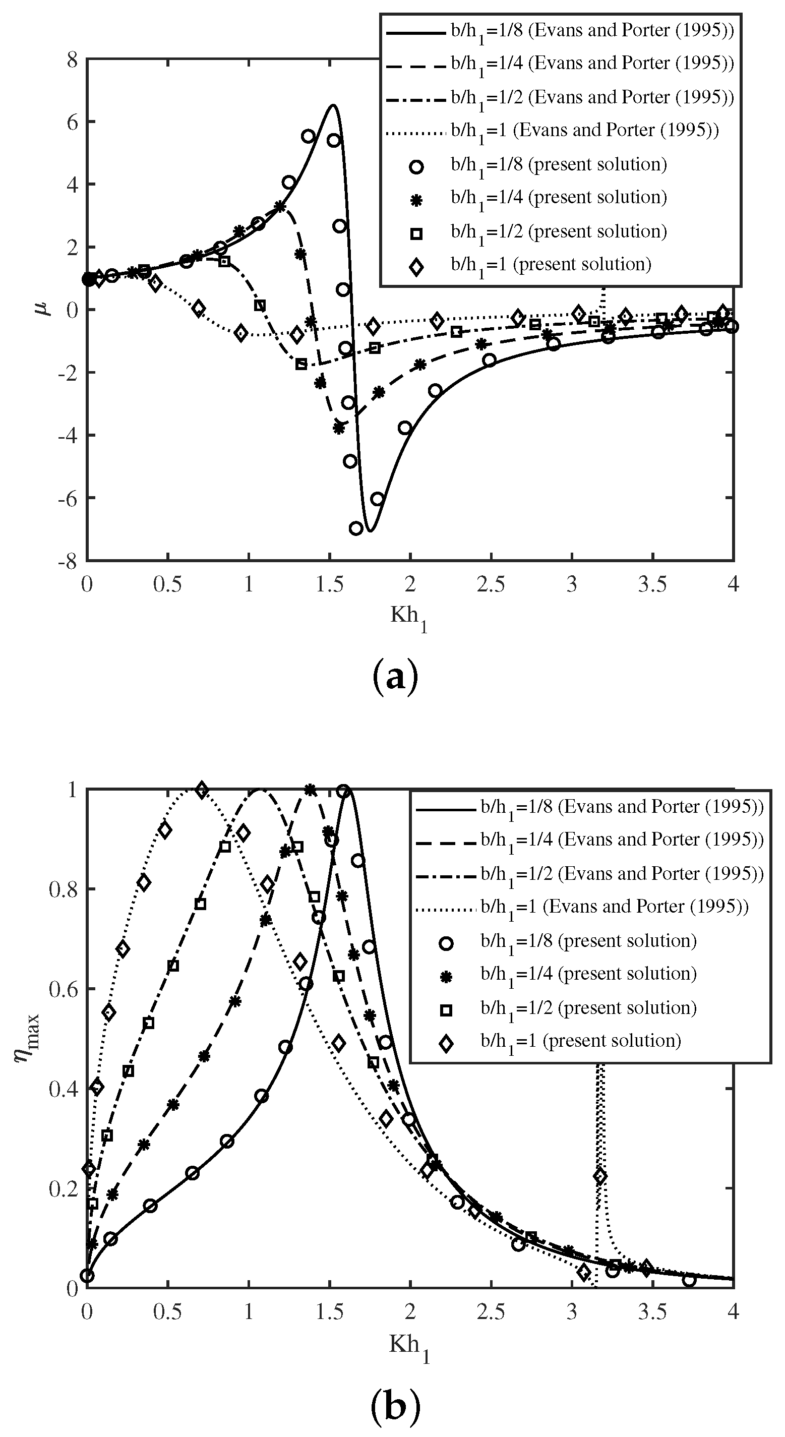
In this section, the comparison between the present numerical results and the results of [1] is provided for specific cases. To achieve the OWC device model of [1], the limiting case of the present model is considered by taking the angle of the incidence and . In Figure 2a, the radiation susceptance is plotted as a function of non-dimensional wavenumber for various values of chamber length . Further, Figure 2b depicts the efficiency as a function of non-dimensional wavenumber for various values of chamber length of the OWC device. Both the figures show that the results obtained using the present DBEM method match well with the results of [1].
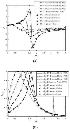
Figure 2.
Comparison of present numerical result with the results of [1] for (a) and (b) vs. for different with .
5.2. Various Results Associated with the U-Shaped OWC Device
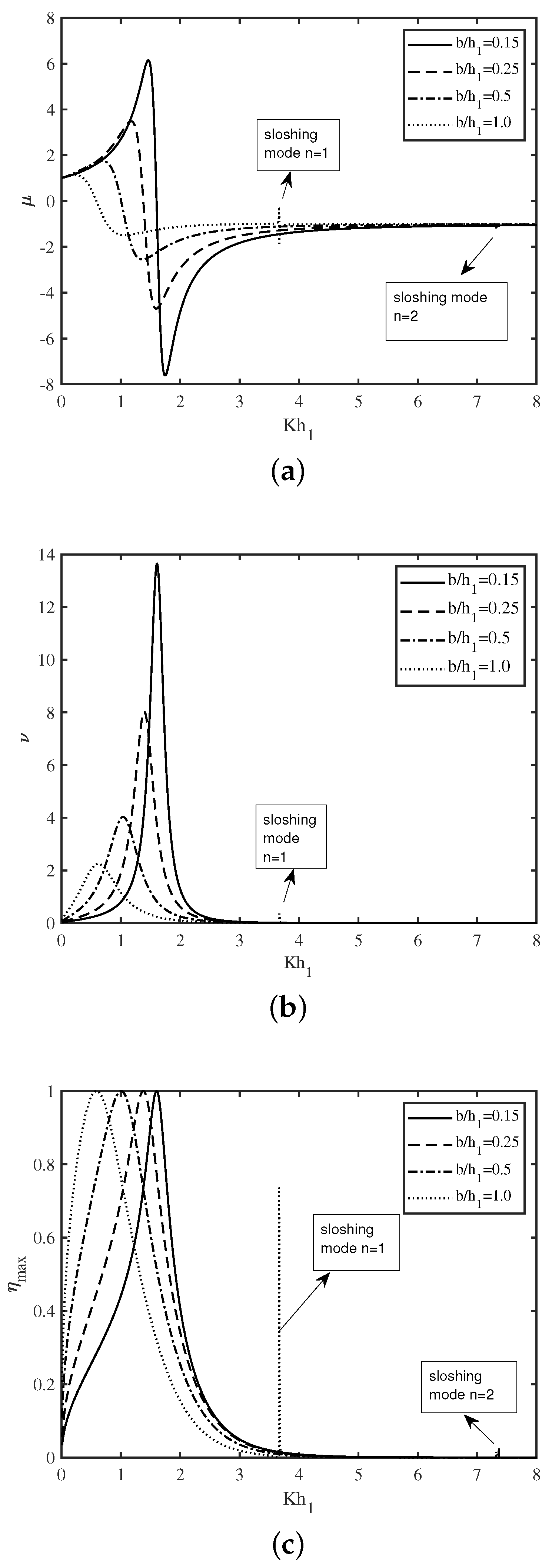
In Figure 3a–c, the variation of the non-dimensional radiation susceptance , radiation conductance , and the efficiency of the device are plotted as a function of non-dimensional wavenumber for various chamber length . Figure 3a–c demonstrate that resonance occurs in the radiation susceptance , radiation conductance and efficiency for certain values of the wavenumber in long and intermediate wave regimes. This resonance arises due to the first resonance mechanism as discussed in [19]. Further, it is seen that this resonance occurs for lower values of the wavenumber with an increase in chamber length . The reason behind this phenomenon is that the distance that the water particles travel during one oscillation increases with an increase in chamber length . Moreover, the resonance amplitude decreases with an increase in chamber length . Now, for large chamber length , the second peak in , and occurs in the neighborhood of due to the second resonance mechanism as discussed in [19]. It is to be noted that this particular resonance corresponds to the sloshing mode number . Moreover, it is observed that smaller peaks in the and curve occur for due to the second resonance mechanism with sloshing mode number . A comparison between the Figure 2 and Figure 3 reveals that the overall pattern of the radiation susceptance and efficiency as a function of wavenumber for the rectangular and U-shaped OWC devices are similar in nature. However, for smaller values of chamber length , the peak in the curve occurs (due to the first resonance mechanism) for smaller values of for the U-shaped OWC device (peak occurs at ) as compared to the rectangular OWC device (peak occurs at ). Further, for higher values of chamber length , the peak in the and curve occurs (due to the second resonance mechanism) for higher values of for the U-shaped OWC device (peak occurs at ) as compared to the rectangular OWC device (peak occurs at ). In summary, the chamber length plays an important role in enhancing the performance of an U-shaped OWC device.
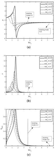
Figure 3.
Variation of (a) , (b) and (c) vs. for different .
In Figure 4a–c, the variation of the non-dimensional radiation susceptance coefficient , radiation conductance coefficient , and the efficiency of the device are plotted as a function of non-dimensional wavenumber for various submergence depth of the front wall of the U-OWC device respectively. In all the figures, the first peak in the curve occurs for smaller values of with an increase in draft of the lip-wall. This resonance arises due to the first resonance mechanism. Further, it is seen that in the short wave regime, the second and third peaks in the , , and curve arise due to the second resonance mechanism with sloshing mode number . It is to be noted that these sloshing phenomena are more prominent for a higher draft of the front wall of the OWC device. Further, it is observed that for , the area under the efficiency curve is more and this area decreases with an increase in . This indicates that with appropriate structural configurations, the OWC device can efficiently harness the wave power over a wide range of incident wave frequencies. A comparison between Figure 4a,c reveals that the efficiency of the U-OWC device becomes higher as takes lower values. This observation can clearly be explained from Equation (29). In summary, it can be concluded that the draft of the front wall of the OWC device plays a vital role in enhancing the efficiency of the U-shaped OWC device.
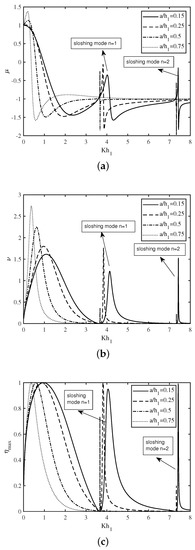
Figure 4.
Variation of (a) , (b) and (c) vs. for different .
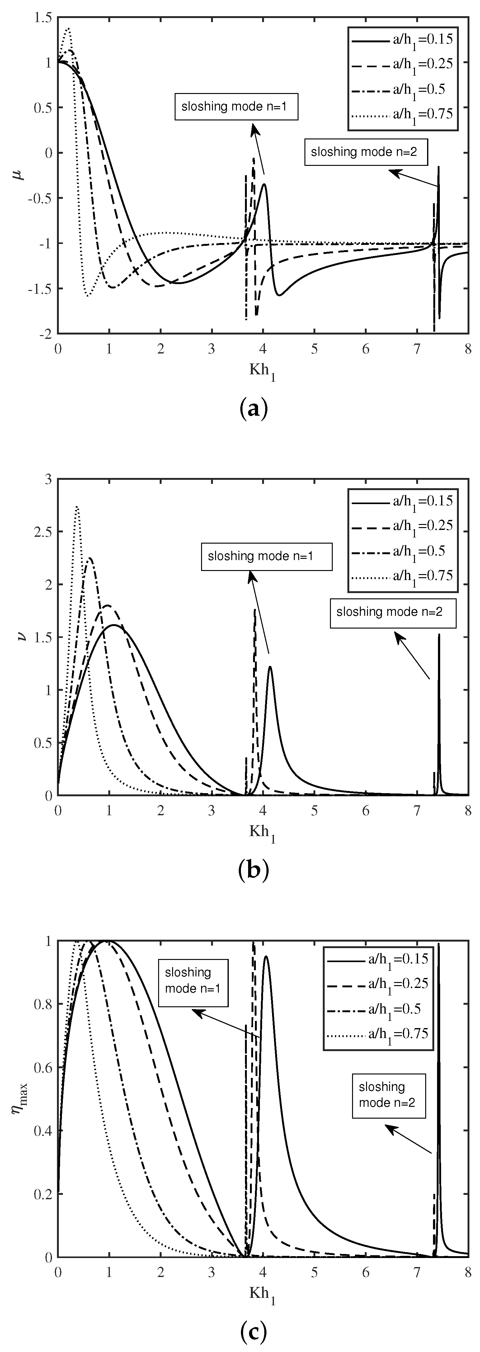
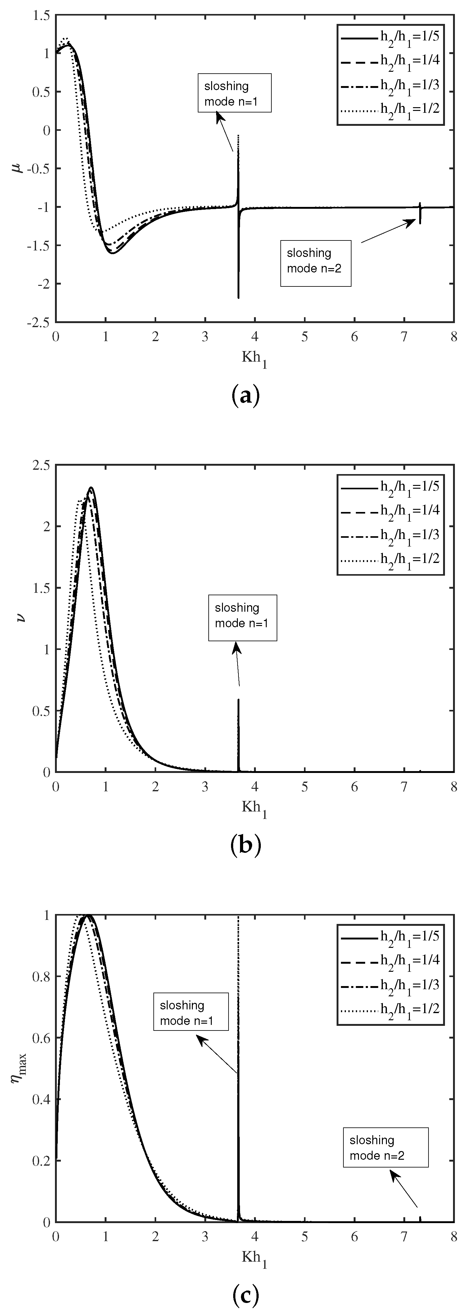
In Figure 5a–c, the variation of the non-dimensional radiation susceptance coefficient , radiation conductance coefficient , and the efficiency of the device are plotted as a function of non-dimensional wavenumber for various submergence depth of the opening duct of the U-OWC device. The overall pattern of Figure 5a–c as a function of wavenumber are similar in nature as that of Figure 4a–c. Further, careful observation reveals that the amplitude of the second resonance is highest for the . The reason for the same is that as increases, the sloshing phenomena become more prominent. On the other hand, for , the area under the efficiency curve is more, and this area decreases as the value of increases. A similar observation is found in Figure 4c. In summary, it can be found that the efficiency of the U-shaped OWC device strongly depends on the submergence depth of the opening duct .
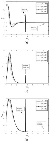
Figure 5.
Variation of (a) , (b) and (c) vs. for different .
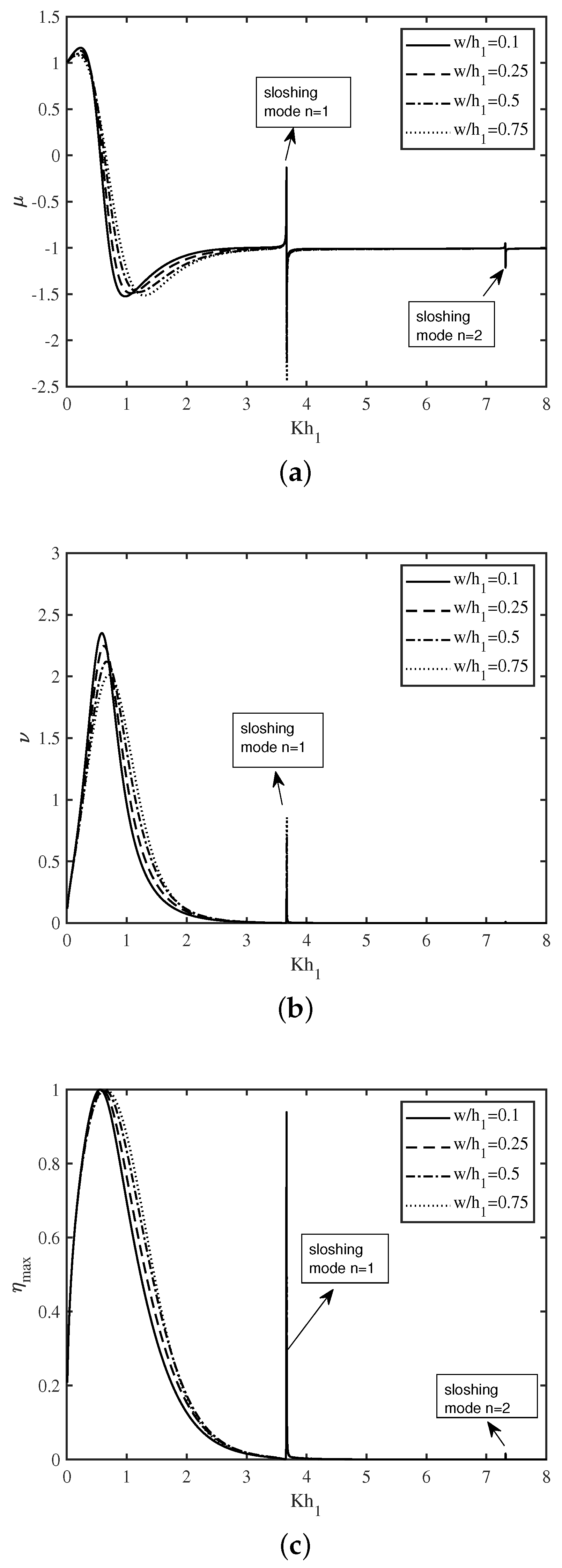
In Figure 6a–c, the variation of the non-dimensional radiation susceptance coefficient , radiation conductance coefficient , and the efficiency of the device are plotted as a function of non-dimensional wavenumber for various width of the opening duct of the U-OWC device. The overall pattern of Figure 6a–c are similar to that of Figure 5a–c. It is observed that for smaller wavenumber , the amplitude of resonance decreases with an increase in . However, in the short wave regime, the amplitude of resonance is highest for the . These observations are similar in nature to that of Figure 3c. These results show that the width of the opening duct plays a key role to improve the hydrodynamic performance of an U-OWC device.
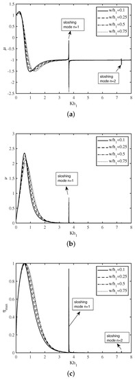
Figure 6.
Variation of (a) , (b) and (c) vs. for different .
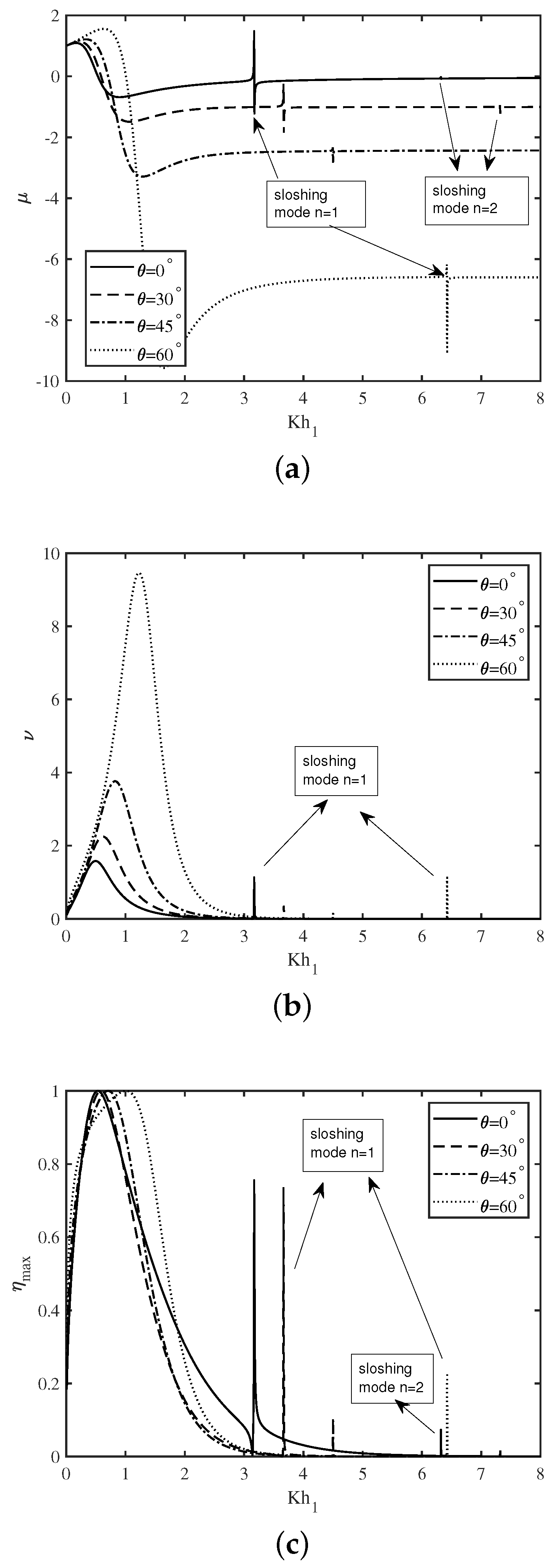
In Figure 7a–c, the variation of the non-dimensional radiation susceptance coefficient , radiation conductance coefficient , and the efficiency of the device are plotted as a function of non-dimensional wavenumber for the various angle of the incidence . Figure 7a depicts that the initially increases for smaller wavenumber with an increase in . Hereafter, decreases sharply and attains a global minimum for the intermediate wave regime. Further, the second and third peaks in the curve arise for higher values of with an increase in incident angle . These resonances occur due to the second resonance mechanism with sloshing mode numbers . Figure 7b illustrates that the amplitude of the resonance increases with an increase in . On the other hand, Figure 7c demonstrates that the resonance in the efficiency occurs for the smaller value of in the long-wave regime. Moreover, the second and third peaks in the efficiency curve arise for higher values of the wavenumber with an increase in the angle of incidence . These results indicate that the efficiency of an U-shaped OWC device strongly depends on the angle of incidence.
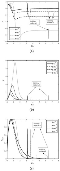
Figure 7.
Variation of (a) , (b) and (c) vs. for various .
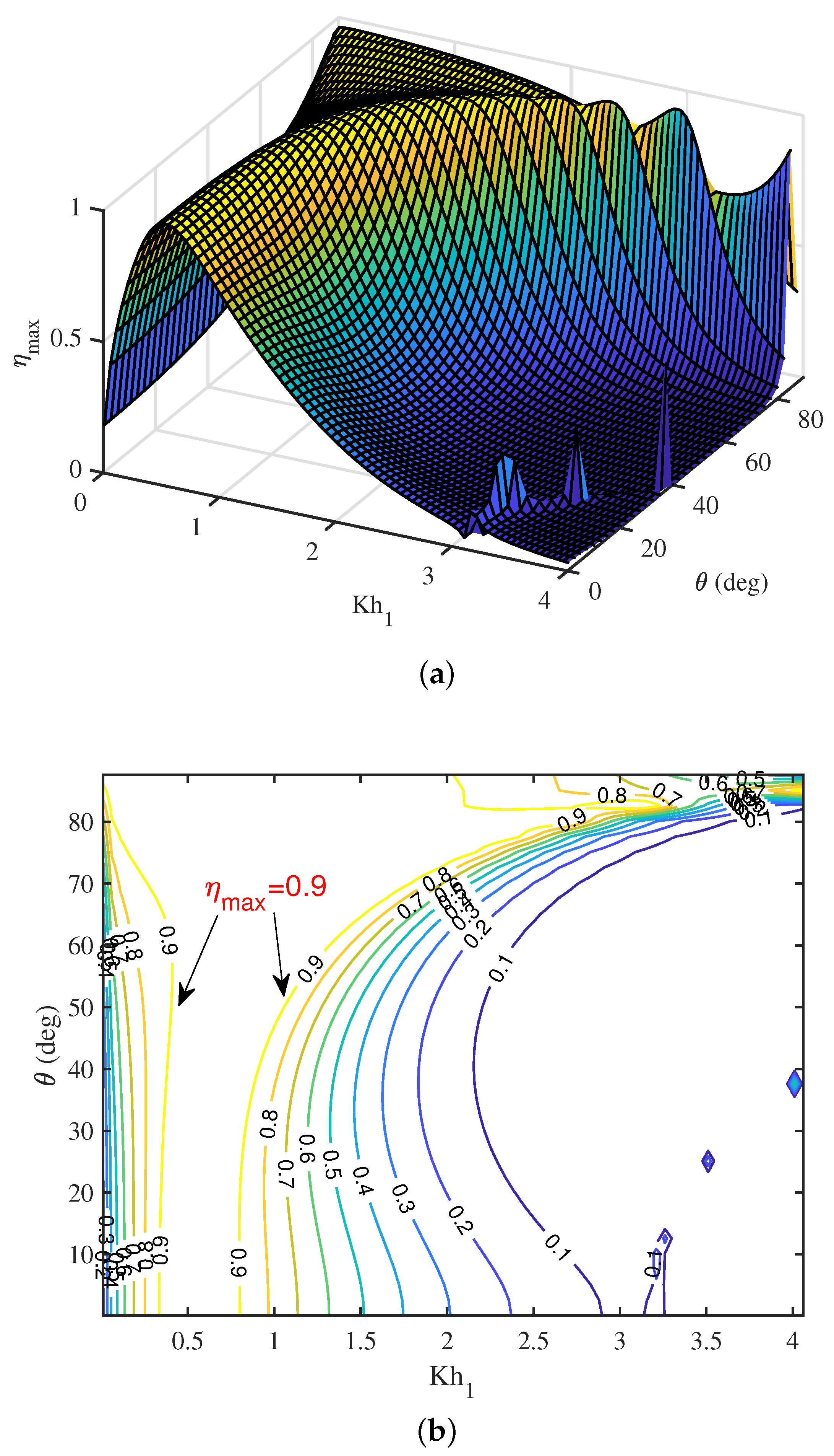
To get a combined effects of wavenumber and angle of incidence on the efficiency , a surface plot for as a function of and is provided in Figure 8a. It is observed that, for moderate values of , the efficiency initially increases with an increase in wavenumber and attains a maximum. Hereafter, the efficiency decreases for further increase in wavenumber except for a certain range of in which resonance occurs due to the second resonance mechanism. However, for higher values of , the efficiency increases with an increase in wavenumber . Further, for smaller wavenumber , the efficiency increases with an increase in . However, in the short wave regime, decreases with an increase in . To get more clarity on the combination of wavenumber and angle of incidence to achieve maximum efficiency , a contour plot is provided in Figure 8b. It is clearly seen that on two different curves. This observation shows that suitable combinations of wavenumber and angle of incidence can result in maximum efficiency of the OWC device.
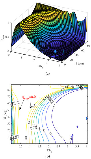
Figure 8.
(a) Surface plot and (b) contour plot of vs. and .
6. Conclusions
In the present study, the hydrodynamic performance of the U-shaped OWC device is analyzed under the action of oblique incident waves. To solve the associated boundary value problem, the dual boundary element method is used. Various physical quantities correspond to the U-OWC device, such as the radiation conductance and susceptance coefficients, and hydrodynamic efficiency are studied for a variety of wave and structural parameters. It is found that the resonance occurs for smaller values of wavenumber with an increase in chamber length. Further, the amplitude of resonance in the radiation conductance and susceptance coefficients decreases as chamber length increases. Moreover, in the short wave regime, the resonance occurs for higher values of the chamber length. A similar resonance pattern is observed for the other shape parameters, such as the submergence depth of the front wall and opening duct, and width of the opening duct, etc. It is observed that with appropriate combinations of the angle of incidence and incident wavenumber, more than efficiency in the U-shaped OWC device can be achieved.
Author Contributions
Conceptualization, S.K. and K.T.; methodology, S.K. and K.T.; software, K.T. and K.P.; validation, S.K. and K.T.; formal analysis, S.K. and K.T.; investigation, K.T.; resources, S.K.; data curation, S.K. and K.T.; writing—original draft preparation, K.T.; writing—review and editing, S.K. and K.T.; visualization, K.P.; supervision, S.K.; project administration, S.K.; funding acquisition, S.K. All authors have read and agreed to the published version of the manuscript.
Funding
K.T. and S.K. acknowledge the DST Project’s financial support: DST/INSPIRE/04/ 2017/002460 to pursue this research work. Further, supports were received through the RIG project: BITS/GAU/RIG/2019/H0631 and Additional Competitive Research Grant: BITS/GAU/ACRG/2019/ H0631 provided by BITS-Pilani, Hyderabad Campus.
Conflicts of Interest
The authors declare no conflict of interest.
Appendix A. Detailed Solution Methodology Based on DBEM
In this section, the detailed procedure to generate a system of four integral equations from Equations (15) and (16), and solving these integral equations using DBEM are discussed. For , Equations (15) and (16) reduced into the following forms
where
For , Equations (15) and (16) reduced into the following forms
where
It is to be noted that in Equations (A3), (A4), (A7) and (A8), the number of unknowns on the degenerate boundaries are double as compared to the unknowns on the non-degenerate boundaries. Therefore, the integral Equation (13) is necessary to obtained unique solutions. By discretizing the boundaries of the domain using the constant boundary element method and varying the field point over each boundary elements, we get the following system of equations
where the influence coefficients and are given by
When the field point and the source point lies on the different boundary element, Gaussian quadrature is used to evaluate the aforementioned influence coefficients. On the other hand, when the field point and the source point lies on the same boundary element, singularity appears, and special treatment is required to evaluate the influence coefficients (details are available in [22]). Now, two different approaches and are available to solve the unknowns (see [22] for details). In the present study, approach is adopted. In this approach, the following system of equations are obtained
References
- Evans, D.V.; Porter, R. Hydrodynamic characteristics of an oscillating water column device. Appl. Ocean Res. 1995, 17, 155–164. [Google Scholar] [CrossRef]
- Zhang, Y.; Zou, Q.P.; Greaves, D. Air-water two-phase flow modelling of hydrodynamic performance of an oscillating water column device. Renew. Energy 2012, 41, 159–170. [Google Scholar] [CrossRef]
- Teixeira, P.R.; Davyt, D.P.; Didier, E.; Ramalhais, R. Numerical simulation of an oscillating water column device using a code based on Navier–Stokes equations. Energy 2013, 61, 513–530. [Google Scholar] [CrossRef]
- Rezanejad, K.; Bhattacharjee, J.; Soares, C.G. Stepped sea bottom effects on the efficiency of nearshore oscillating water column device. Ocean Eng. 2013, 70, 25–38. [Google Scholar] [CrossRef]
- Malara, G.; Arena, F. Analytical modelling of an U-Oscillating Water Column and performance in random waves. Renew. Energy 2013, 60, 116–126. [Google Scholar] [CrossRef]
- Jin, J.; Hyun, B.S.; Hong, K.; Liu, Z. Performance of Oscillating Water Column type Wave Energy Converter in Oblique Waves. J. Korean Soc. Mar. Environ. Energy 2014, 17, 182–188. [Google Scholar] [CrossRef]
- Ning, D.Z.; Shi, J.; Zou, Q.P.; Teng, B. Investigation of hydrodynamic performance of an OWC (oscillating water column) wave energy device using a fully nonlinear HOBEM (higher-order boundary element method). Energy 2015, 83, 177–188. [Google Scholar] [CrossRef]
- Rezanejad, K.; Bhattacharjee, J.; Soares, C.G. Analytical and numerical study of dual-chamber oscillating water columns on stepped bottom. Renew. Energy 2015, 75, 272–282. [Google Scholar] [CrossRef]
- Rezanejad, K.; Bhattacharjee, J.; Soares, C.G. Analytical and Numerical Study of Nearshore Multiple Oscillating Water Columns. J. Offshore Mech. Arct. Eng. 2016, 138, 021901. [Google Scholar] [CrossRef]
- Viviano, A.; Naty, S.; Foti, E.; Bruce, T.; Allsop, W.; Vicinanza, D. Large-scale experiments on the behaviour of a generalised Oscillating Water Column under random waves. Renew. Energy 2016, 99, 875–887. [Google Scholar] [CrossRef]
- John Ashlin, S.; Sannasiraj, S.A.; Sundar, V. Hydrodynamic performance of an array of oscillating water column device exposed to oblique waves. In Proceedings of the 12th International Conference on Hydrodynamics, Egmond aan Zee, The Netherlands, 18–23 September 2016. [Google Scholar]
- Strati, F.M.; Malara, G.; Arena, F. Performance optimization of a U-Oscillating-Water-Column wave energy harvester. Renew. Energy 2016, 99, 1019–1028. [Google Scholar] [CrossRef]
- Vyzikas, T.; Deshoulières, S.; Barton, M.; Giroux, O.; Greaves, D.; Simmonds, D. Experimental investigation of different geometries of fixed oscillating water column devices. Renew. Energy 2017, 104, 248–258. [Google Scholar] [CrossRef]
- Rezanejad, K.; Soares, C.G.; López, I.; Carballo, R. Experimental and numerical investigation of the hydrodynamic performance of an oscillating water column wave energy converter. Renew. Energy 2017, 106, 1–16. [Google Scholar] [CrossRef]
- Spanos, P.D.; Strati, F.M.; Malara, G.; Arena, F. An approach for non-linear stochastic analysis of U-shaped OWC wave energy converters. Probabilistic Eng. Mech. 2020, 54, 44–52. [Google Scholar] [CrossRef]
- Raj, D.D.; Sundar, V.; Sannasiraj, S.A. Enhancement of hydrodynamic performance of an Oscillating Water Column with harbour walls. Renew. Energy 2019, 132, 142–156. [Google Scholar]
- Malara, G.; Arena, F. Response of U-Oscillating Water Column arrays: Semi-analytical approach and numerical results. Renew. Energy 2019, 138, 173–187. [Google Scholar] [CrossRef]
- Jalón, M.L.; Brennan, F. Hydrodynamic efficiency versus structural longevity of a fixed OWC wave energy converter. Ocean Eng. 2020, 206, 107260. [Google Scholar] [CrossRef]
- Koley, S.; Trivedi, K. Mathematical modeling of oscillating water column wave energy converter devices over the undulated sea bed. Eng. Anal. Bound. Elem. 2020, 117, 26–40. [Google Scholar] [CrossRef]
- Katsikadelis, J.T. The Boundary Element Method for Engineers and Scientists: Theory and Applications; Academic Press: Cambridge, MA, USA, 2016. [Google Scholar]
- Chen, J.T.; Yueh, C.Y.; Chang, Y.L.; Wen, C.C. Why dual boundary element method is necessary? Eng. Anal. Bound. Elem. 2017, 76, 59–68. [Google Scholar] [CrossRef]
- Chen, K.H.; Chen, J.T.; Chou, C.R.; Yueh, C.Y. Dual boundary element analysis of oblique incident wave passing a thin submerged breakwater. Eng. Anal. Bound. Elem. 2002, 26, 917–928. [Google Scholar] [CrossRef]
- Chen, K.H.; Chen, J.T.; Lin, S.Y.; Lee, Y.T. Dual boundary element analysis of normal incident wave passing a thin submerged breakwater with rigid, absorbing, and permeable boundaries. J. Waterw. Port Coast. Ocean Eng. 2016, 130, 179–190. [Google Scholar] [CrossRef]
- Vijay, K.G.; Venkateswarlu, V.; Nishad, C.S. Wave scattering by inverted trapezoidal porous boxes using dual boundary element method. Ocean Eng. 2021, 219, 108149. [Google Scholar] [CrossRef]
Publisher’s Note: MDPI stays neutral with regard to jurisdictional claims in published maps and institutional affiliations. |
© 2021 by the authors. Licensee MDPI, Basel, Switzerland. This article is an open access article distributed under the terms and conditions of the Creative Commons Attribution (CC BY) license (https://creativecommons.org/licenses/by/4.0/).

