Abstract
Suction feeding is a well-understood feeding mode among macroscopic aquatic organisms. The little we know about small suction feeders from larval fish suggests that small suction feeders are not effective. Yet bladderworts, an aquatic carnivorous plant with microscopic underwater traps, have strong suction performances despite having the same mouth size as that of fish larvae. Previous experimental studies of bladderwort suction feeding have focused on the solid mechanics of the trap door’s opening mechanism rather than the mechanics of fluid flow. As flows are difficult to study in small suction feeders due to their small size and brief event durations, we combine flow visualization on bladderwort traps with measurements on a mechanical, dynamically scaled model of a suction feeder. We find that bladderwort traps generate flows that are more similar to the inertia-dominated flows of adult fish than the viscosity-dominated flows of larval fish. Our data further suggest that axial flow transects through suction flow fields, often used in biological studies to characterize suction flows, are less diagnostic of the relative contribution of inertia versus viscosity than transverse transects.
1. Introduction
Suction is a force exerted on a fluid or solid suspended in a fluid in the presence of a sub-ambient pressure. Aquatic organisms employ suction to transport food items into their mouth. Suction feeding is used by many macroscopic aquatic vertebrates, who often combine suction with other strategies such as ram feeding and jaw protrusion that do not rely on creating a pressure gradient [1,2,3,4,5]. Suction feeding has been studied most extensively in fish [1,2,3,4,5,6,7,8], but also in tadpoles [9], aquatic salamanders [10], and seals [11]. While tadpoles currently hold the record for smallest vertebrate suction feeders, sharks hold the record for strongest suction pressures [9,12]. Suction feeding is also found in the carnivorous plants of the genus bladderwort (genus Utricularia), which capture zooplankton in tiny underwater suction traps [13,14]. The suction flows generated by large suction feeders have been described extensively [6,15,16]: adult fish generate strong sub-ambient pressures by opening their mouth and expanding their buccal cavity [17,18,19]; their suction pressures range from 1.5 to 55.6 kPa and produce strong flows of 1.4 to 6.8 m·s−1, measured typically at half gape from the plane of the mouth [6,17,18,19,20,21,22]. Flow speed declines quickly with distance from the mouth [15,21,23] in a manner that is described well by inviscid flow models [24].
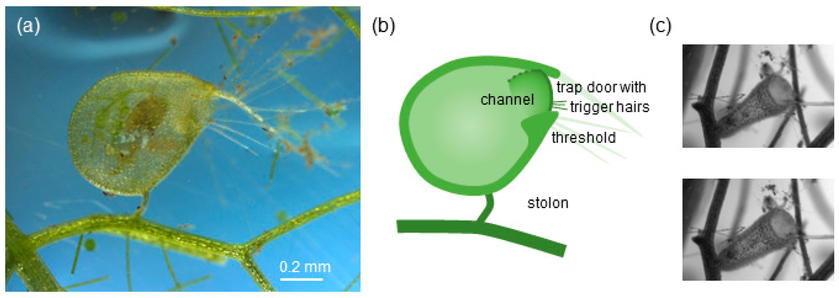
Bladderworts differ from animal suction feeders in several ways. Whereas animal suction feeders can use a combination of direct muscle power and elastic energy stores [25,26,27,28], bladderwort traps rely exclusively on elastic energy to power their suction events [29,30]. Bladderwort traps consist of a hollow lenticular bladder that is sealed by a dome-shaped trap door [29,31,32] (Figure 1). Traps are set by evacuating the water that fills the trap lumen, which causes the trap walls to bend inward and become elastically loaded [30,33,34] (Figure 1c). This elastic loading generates a sub-ambient pressure of 10 to 17 kPa inside the trap [30,33,34,35,36]; these values are similar to the sub-ambient pressures generated by adult fish (1 to 110 kPa) [12,17,18]. The trap is triggered when prey deflect trigger hairs on the outside of the trap door, causing the door to buckle and open, and the prey to be sucked into the trap [31,37]. These elastic-energy-powered suction events have a fast onset compared with animal suction feeders that rely on direct muscle power: bladderwort traps open their trap door within 0.3 to 4 ms [32,37], elastically powered seahorses reach peak gape in 2.6 ms or less [22,38], in contrast to directly muscle-powered animal suction feeders’ times to peak gape, which range from 3 to 104 ms [18,22,39]. These brief onset times mean that time to prey capture is also very brief in bladderwort, making bladderwort the fastest suction feeder [29,32].
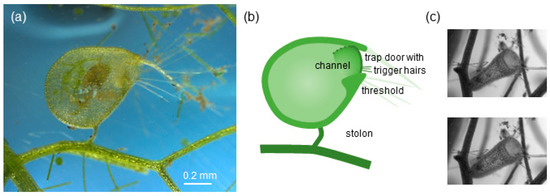
Figure 1.
Trap of aquatic bladderwort Utricularia sp. of the vulgaris trap type [32]. (a) Lateral view of a single vulgaris-type trap; the trap contains a prey item (ostracod). (b) Sketch of a vulgaris-type trap; the trap mouth is surrounded by long bristles (light green) and is closed off by a dome-shaped trap door (dark green line) with trigger hairs (fine dark green lines); as the door opens inward (dotted green line), it forms a channel between the door and the threshold. (c) Frontal view of a vulgaris-type trap, before (top panel: loaded trap) and after triggering (bottom panel: unloaded trap).
Bladderwort traps are not only the fastest, but also among the smallest suction feeders. Their traps range in diameter from 0.5 to 12 mm [29,32,40,41], with corresponding gape diameters (measured as the diameter of the trap door) ranging from 0.2 to 1.3 mm [32,40]. The smallest traps are similar in gape diameter to first-feeding fish larvae and tadpoles with gapes ranging from 0.2 to 0.6 mm [9,42,43,44,45]. Because suction flows on such a small scale tend to be degraded by viscosity, the apparent effectiveness of bladderwort is of interest to biologists and engineers. Previous studies on the flows generated by small suction feeders suggest that they generate weak suction pressures and weak suction flows that more closely resemble viscous inhalant flows [46,47,48,49,50,51]. Unfortunately, the real bladderwort suction event is difficult to study because of its small size and short duration. In order to increase the spatial and temporal resolution of experimentally measured flow fields, we have designed a dynamically scaled model to characterize the traps’ suction flows.
In this study we compare the suction flow profile of bladderwort traps with theoretical predictions for inviscid and creeping flow into an orifice or through a contraction [24,52,53] as well as with predictions of the dynamically scaled model [54]. We chose bladderwort as our model organism for a small suction feeder because its suction mechanism is not complicated by supplementary strategies such as ram feeding or jaw protrusion, making bladderwort a suitable organism to compare its suction flows with theoretical and mechanical-model predictions. These comparisons serve two main aims. First, we aim to demonstrate that dynamically scaled models are a suitable tool to explore suction flows in sufficient spatial detail to compare experimental data with theoretical predictions about inhalant flows [49,50,51,52]. Second, we aim to position the suction flows of bladderwort traps relative to the suction flows of adult and larval fish (Table 1) [15,21,47]. On the one hand, the traps are similar in size to larval fish, on the other hand they generate suction pressures similar to adult fish. Their small size and strong suction flows should place them at an intermediate position between the viscosity-impaired suction flows of larval fish [46,47,48] and the inertia-dominated suction flows of adult fish. In this intermediate regime, both viscous and inertial forces play a significant role, and organisms are adapted both to overcome fluid-dynamic constraints and to exploit corresponding opportunities [55,56,57]. In this study, we aim to characterize the flow generated by bladderwort traps during a suction event and compare their flow with findings from studies on other small suction feeders, in particular larval zebrafish and sea bream [46,47,58].

Table 1.
Suction characteristics of bladderwort traps and fish.
2. Materials and Methods
In this study, we collect flow data from two types of suction feeders: a biological suction feeder (bladderwort traps) and a mechanical suction feeder (dynamically scaled model of a bladderwort trap). The mechanical model is not isomorphic, but reflects core structural and kinematic elements of the traps [54].
2.1. Flow Data from Biological Suction Feeders
2.1.1. Material
We purchased bladderwort, Utricularia gibba, from Carnivorous Plant Nursery (Derwood, MD, USA). Plants were cultivated in the CSU Fresno greenhouse in a 250-gallon basin containing medium made from dried sphagnum moss and distilled water, following established care instructions for Utricularia [60]. The medium was prepared at pH 5.7 with low nutrient levels and high levels of organic carbon, which acts as a pH buffer; total dissolved solids (TDS, a measure of dissolved ions and nutrients) were kept to 60–80 ppm. Temperature was maintained in a range of 25–35 °C. Day-time light levels within the greenhouse were typically between 400 and 650 foot-candles. We collected zooplankton from the pond within the campus greenhouse facilities to feed the plants.
2.1.2. Flow Visualization Using Bladderwort Traps
We excised mature traps with their complete stolon using micro-surgery scissors (Roboz Surgical Instruments, Gaithersburg, MD, USA) (Figure 1), then used cyanoacrylate cement (Loctite Super Glue Gel) to attach the stolon to a fine wire. The mounted trap was positioned in a glass cuvette (10 × 10 × 15 mm3, Starna, Atascadero, CA, USA) at least two gape diameters away from the cuvette walls. Individual traps were chosen because their flat appearance indicated an evacuated condition. Traps were typically 1.0 to 1.5 mm in diameter, and the external diameter of their mouth ranging from 0.27 to 0.42 mm (Figure 1, Table 1).
We recorded suction flows by illuminating the trap with a laser diode (Stocker-Yale/Coherent Lasiris TMFL, 200 mW at 810 nm; Coherent, Santa Clara, CA, USA) that produced a light sheet thin in one transverse direction (50 µm waist) and elongated but uniformly intense in the other. Alignment of the trap with the laser sheet was confirmed by systematic translation of the bladder along the optic axis using a micrometer-driven translation stage (Newport). All recordings were made with a Phantom V12.1 high speed camera (1280 × 800 pixels, Vision Research, Wayne, NJ, USA); a frame rate of 10,000 Hz was reached by lowering the field of view to 800 × 600 pixels. The macro imaging system consisted of a 24 mm objective lens (Nikon), mounted with a reversing ring on a 105 mm ocular (Nikon), resulting in a magnification of 105/24 = 4.4 at ~f/1.7. With a field of view 4.0 mm × 3.0 mm in the laser sheet, the resolution was 210 px/mm. To record flow, the water in the cuvette was seeded with nylon particles (Vestosint, diameter 6 μm, BASF, Ludwigshafen, Germany). Most feeding strikes were triggered artificially by touching the bladder’s trigger hairs with a cat eyebrow whisker that was mounted on a mechanical micro-manipulator (Narashige International USA, Amityville, NY, USA); a minority of events were triggered by introducing live ostracods to the cuvette, and waiting.
We used particle image velocimetry (PIV) to analyze our data. Each frame of a video sequence was converted to an uncompressed 12-bit tiff image. Velocity vectors were calculated using the Mathworks MATLAB toolbox “PIVlab” (pre-processing: Contrast Limited Adaptive Histogram Equalization (CLAHE) (Mathworks, Inc., Matlab Version 2013B, Natick, MA, USA), window size 20 × 20 px2; high-pass filter, kernel size 15 × 15 px2; Wiener2 denoise filter, window size 3 px; PIV: FFT window deformation algorithm; two-pass PIV with interrogation area 64 × 64 px2, step 32 px and interrogation area 32 × 32 px2, step 16 px) [61]. We followed established recommendations for PIV analysis for imaging and correlation procedures (such as seeding density: 8 to 10 particles per first-pass interrogation area; particle image: 2 to 3 pixels in size; grey scale values unsaturated; particle displacement less than one-third of the interrogation area; overlap between interrogation areas: 50%) [61,62,63]. Further processing of the resulting vectors was performed with Mathematica (Wolfram Research, Inc., Mathematica Version 11.0, Champaign, IL, USA): scale factors and symmetry axes were obtained from representative frames of the video and flow field, then speed distributions were computed from the set of vectors lying closest to a point or linear transect (please refer to figures in the Results section for a visual explanation). We followed the procedures described in [15,21] to scale the axial transects: each range value (position of the vector along the transect) was divided by the measured gape diameter to yield dimensionless distance; the corresponding vector norms were then scaled so as to set the measured speed at half gape range equal to unity. The choice of scaling factor was over-sensitive to random error if a single data point was used. Therefore, each transect was first fit to a Gaussian. This smoothed curve was then scaled so as to reach unity at half gape; then the scaling factor was applied to the measured speed values.
2.2. Flow Data From Mechanical Suction Feeders
2.2.1. Designing a Dynamically Scaled Model of a Suction Feeder
In order to increase the spatial and temporal resolution of experimentally measured flow fields, we designed a dynamically scaled model for study by Particle Image Velocimetry. The start-up time for a bladderwort feeding strike is less than 0.1 ms [53]; this study focuses on events after 0.1 ms, when the external flow is no longer time-dependent. We therefore use Reynolds number rather than Womersley number to scale the model.
Linear dimensions in the model were scaled up by a factor of 320 (32 mm vs 0.10 mm) based on the fluid-flow bottleneck observed in a typical specimen of U. gibba [53]. Although a proportional decrease in flow speed would preserve Reynolds number, it would lead to impractically long event durations. Therefore we chose a working fluid of 70 × greater viscosity than water (CP200FG mineral oil; STE Oil Company), and decreased the bulk flow speed by a factor of 320/70. Operating thus at a Reynolds number comparable to bladderwort, the relative dimensions of the vector flow field were maintained. Time duration in the model was effectively scaled up by a factor of 1470, for video recordings on the order of 1 s (vs 0.68 ms in the bladderwort trap, which exceeds the start-up time of the trap’s suction flow by a factor of ~7).
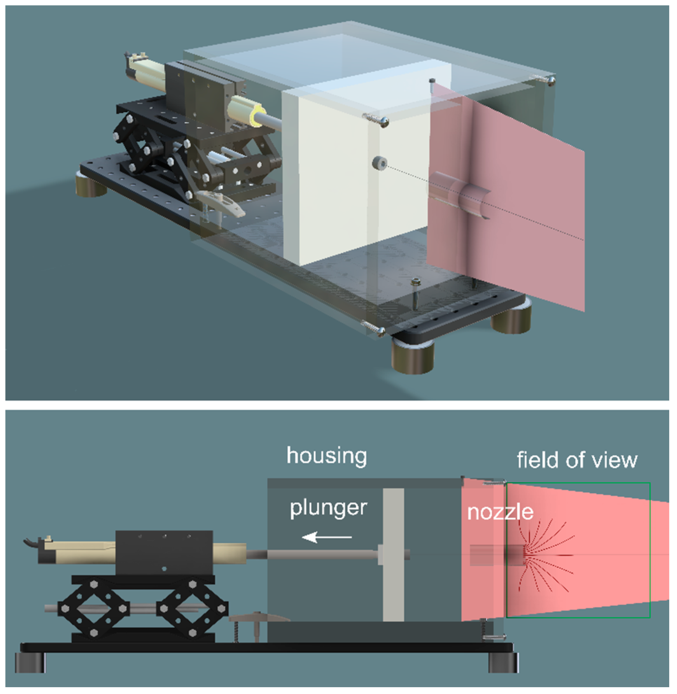
The model consisted of a plunger and housing that force oil through a test nozzle (Figure 2) (Precision Plastics, Clovis, CA, USA). The plunger was driven by an electromagnetic linear actuator and control system (LinMot, Spreitenbach, Switzerland). The model was not designed be literally isomorphic with a biological suction feeder: the test nozzle had a circular cross section (diameter: 32 mm, length: 53 mm) and opened into a housing of square cross section. This idealized design captured key features of organismal suction feeders, in particular that the surface driving the suction flow is two orders of magnitude larger than the cross-section of the flow bottleneck. Thus fluid speeds are only significant in the volume immediately upstream, inside, and immediately downstream of the nozzle. This design reflects that many organismal suction feeders, including bladderwort traps, suck through a short nozzle of finite length into a large reservoir of increasing volume. The nozzle and housing were constructed from acrylic, which closely matches the refractive index of heavy mineral oil, allowing us to photograph internal flows.
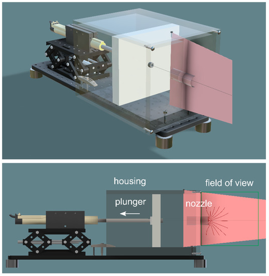
Figure 2.
Sketch (perspective and elevation) of the mechanical suction-feeder model, showing the plunger (grey plate, area 191 mm × 191 mm) within its housing (transparent box) mounted onto a breadboard (black base); the actuator is mounted on a laboratory jack and withdraws the plunger to create a suction flow into the nozzle (cylinder mounted into the face plate of the housing); a laser sheet (red) illuminates the flow near the nozzle. The mechanical model is submerged in a 200 L tank containing mineral oil.
2.2.2. Flow Visualization Using a Dynamically Scaled Model
To visualize the suction flows generated by the mechanical model, the oil in the tank was seeded with air bubbles blown through a ceramic water filter. The dispersion was allowed to settle for several minutes, until the bubble size (<1 mm) and seeding density (1–5 per interrogation area) were suitable for PIV analysis. The bubbles were illuminated by a diode laser light sheet (Stocker-Yale / Coherent Lasiris Powerline; 1500 mW at 810 nm) and recorded with a Phantom V12.1 camera (1280 × 800 pixels, Vision Research, Wayne, NJ, USA) at a frame rate of 1000 Hz. With a field of view 187 mm × 117 mm in the laser sheet (Nikon 105 mm AF Micro Nikkor, f/2.8), the resolution was 6.8 px/mm; 150 μs exposures produced non-saturated particle images with sub-pixel motion blur. We collected flow data for a suction run simulating conditions typical for a bladderwort trap and for a suction run simulating conditions typical for a first-feeding fish larva. To simulate the feeding strike generated by a bladderwort trap (high velocity/strong pressure) and larval fish (low velocity/weak pressure), the bulk flow speed in the test section was set to 0.54 m s−1 (Reynolds number Re = 250) and 0.002 m s−1 (Re = 1), respectively. These Reynolds numbers are based on experimental observations of bladderworts and larval fish, following conventions for experimental studies on suction feeding [21] that use channel diameter as the characteristic length and peak flow speed near the mouth or bulk flow speed inside the channel [46,47,53].
PIV analysis parameters were identical to those used for live bladderwort, as specified above. Following the conventional scaling procedure [15,21], each range value (position of the vector along the transect) was divided by the nozzle diameter to yield dimensionless distance; the corresponding vector norms were then scaled so as to set the measured value at 1/2 diameter range equal to unity.
Both video sequences from the robotic model were recorded under steady-state conditions, as confirmed by transects of local fluid speed in time. Axial and radial transects represent a time-averaged vector field obtained at steady state: at each vector position, the arithmetic mean components were calculated from 200 sequential frames. Minor irregularities due to bubble seeding and shadows were thereby suppressed.
3. Results
We aim to characterize the suction flows of bladderwort traps in two stages: we begin with experimental observations on actual traps, which yield the parameters used to tune the dynamically scaled model; subsequent measurements on the model yield flow fields of greater sensitivity, resolution, and experimental control.
3.1. Suction Flows of Bladderwort Traps
From 60 recordings of U. gibba, we chose the 15 events with a sufficiently high density of tracer particles to allow detailed analysis. The peak flow speeds within this set of 15 events ranged from 0.03 to 0.20 m s−1 (mean peak speed 0.10 ± 0.05 m s−1, n = 15). Three of the analyzed sequences were triggered by prey, 12 were triggered artificially; five were recorded from a frontal view, ten from a lateral view. The 15 traps in these recordings ranged in gape size from 0.27 to 0.42 mm (mean gape diameter 0.34 ± 0.05 mm, n = 15) (Appendix A). The sevenfold range in peak flow speed may be due to differences in the traps’ loading status. Immediately after firing, traps are conspicuously bulbous (Figure 1). Over subsequent hours they reach a steady loaded condition and flattened appearance [30,33]. Thus bladders occur naturally in a range of states of loadedness, and can be partially relaxed by mechanical stress during handling.
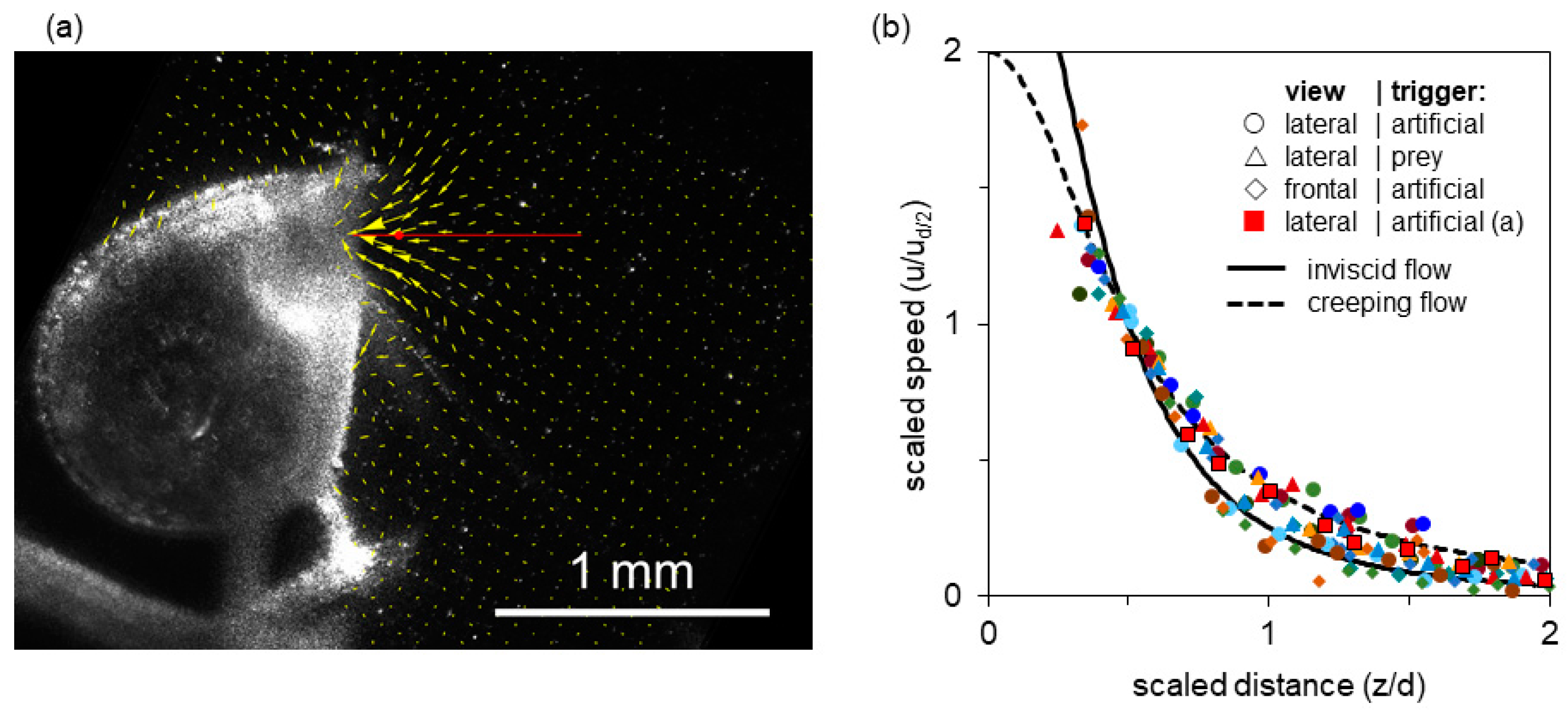
Figure 3a shows a single video frame from a relatively high-speed, high-volume suction event. The resultant PIV vector field is superimposed. The axial transect extending two gape diameters into the bulk fluid is shown in red (with a red dot at the half-gape point). The vector magnitudes along this transect are plotted in Figure 3b (red squares). The flow field shows a steep velocity gradient, with speed increasing rapidly near the mouth, and good axial symmetry (Figure 3a). The centerline transects through the flow field show that flow speed rises sharply within half a gape from the mouth and that suction flow is weak beyond one gape from the mouth (Figure 3b). Because the flow is axisymmetric for a round opening, there is no out-of-plane velocity component in a properly aligned light sheet, and thus the planar PIV results accurately capture the volumetric flow dynamics.
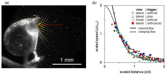
Figure 3.
Flow generated by a bladderwort trap. (a) Single video frame obtained near peak flow (0.2 m s−1), with the corresponding PIV vector field superimposed (field of view 1.9 × 1.9 mm2). Indicated by a red line is the axial transect shown in (b); the half-gape point is marked with a red dot. (b) Fluid speed as a function of distance from the mouth along the axial transect; distances are normalized by gape diameter d and flow speeds normalized by the speed at half gape diameter ud/2. Data are shown for 15 suction events (event in (a): red squares). Both axes have been scaled to match dimensionless theoretical curves for entry flow through a circular orifice: inviscid flow (solid line) and creeping flow (dashed line), see main text (Discussion). Thus data and theory necessarily intersect at distance = 1/2, speed = 1.
Figure 3b overlays the spatial distribution of axial fluid flow speeds of all 15 recorded strikes. In all cases, the transects represent a time shortly after the flow-speed maximum, at which time the flow is in steady state [53]. The various events span a sevenfold range of absolute peak speeds. To the extent that these scaled transects overlap, they have a common range parameter (a gape-relative distance over which the speed drops by a common factor). This choice of coordinates was motivated by theoretical models, which are represented by solid and dashed lines in the plot, and explained in the Discussion. The transects show that despite the sevenfold range in peak speed, all 15 events collapse into a cloud of points, where the between-events variation in flow speed at a given distance from the mouth is much smaller than the with-event variation of flow speed as a function of distance from the mouth (Figure 3b).
3.2. Suction Flows of a Dynamically Scaled Model
The flow fields obtained from the mechanical model (Figure 4) are significantly more uniform than those from the live plant (Figure 3). The nozzle entry is free of structures that interfere with flow and imaging; the particle images are better suited to the camera resolution; and single-frame irregularities of seeding and illumination are removed by averaging. The result is a higher density of useful vectors, suppression of peak-locking artifacts, and less random error in the transects.
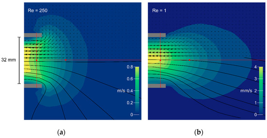
Figure 4.
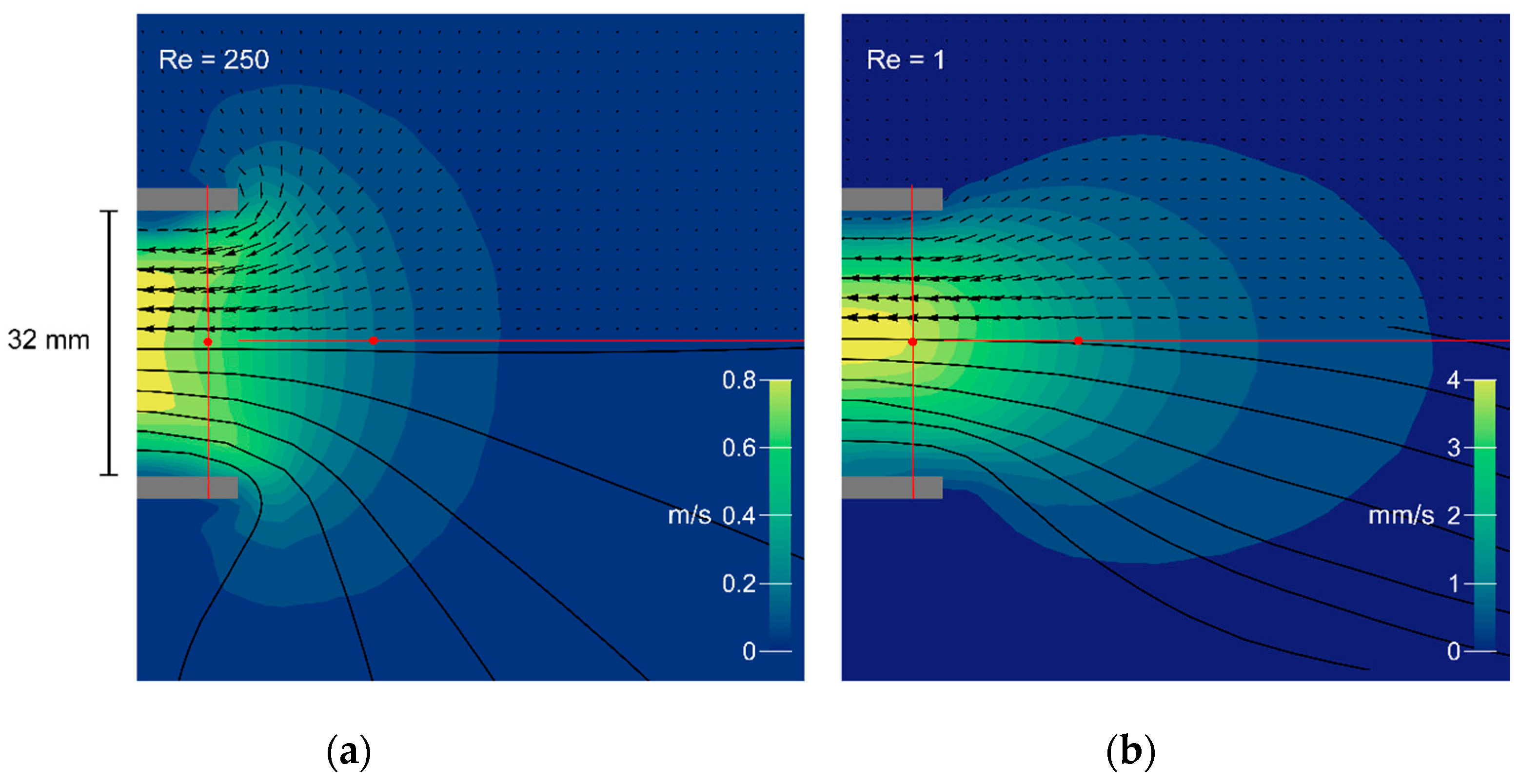
Flow fields generated by the mechanical model at Re = 250 (a) and Re = 1 (b). Magnitudes are represented by color contours; flow direction is indicated by vectors and streamlines in black. Grey bars show the nozzle in cross section (inner diameter 32 mm). The axial and radial transects are illustrated in red, and the corresponding vector magnitudes are plotted in Figure 5a–c below).
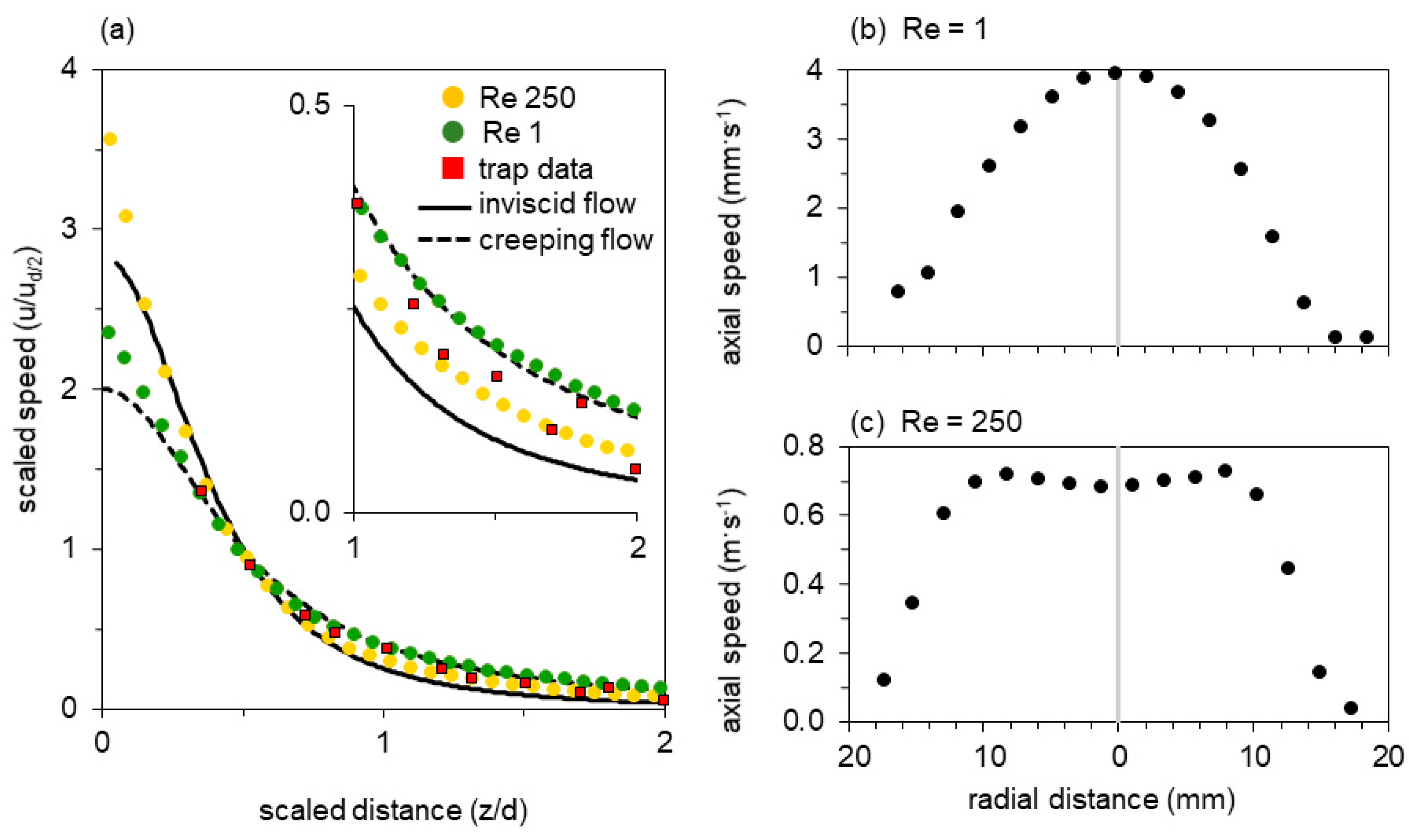
We recorded flow fields for two conditions—one simulating the flow typical for a bladderwort trap (Figure 4, Re = 250), and one simulating the flow typical for a larval fish (Figure 4, Re = 1). Figure 4 shows the flow field in the axial plane of the model’s suction cylinder, with the magnitude of the velocity vectors indicated by the contour map and the PIV velocity field superimposed as experimentally determined arrows (upper half). Approximate streamlines (lower half) were obtained by linear interpolation of the experimental vectors. The different Re calculated from the bulk flow speeds are reflected in a 200-fold difference in the speed scales. The normalized vector magnitudes along the axial transect are plotted in Figure 5a (Re = 1, green dots; Re = 250, yellow dots), below.
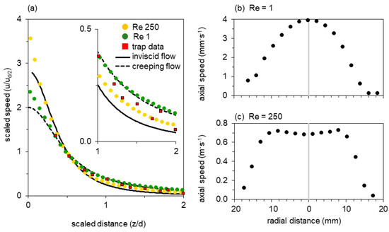
Figure 5.
Transects through the flow fields of the mechanical model at Re 1 and Re 250 as indicated in Figure 4. (a) Fluid speed as a function of distance from the mouth along the axial transect, showing distances normalized by gape and flow speeds normalized by the speed at half gape. Both axes have been scaled to match the dimensionless theoretical curves for entry flow to a circular pipe: inviscid flow (solid line) and creeping flow (dashed line), see main text (Discussion). Thus data and theory necessarily intersect at distance = 1/2, speed = 1. (b,c) Fluid speed as a function of position along a transverse transect within the nozzle for (b) Re = 1 and (c) Re = 250.
Both flow fields show a steep velocity gradient, with speed increasing rapidly near the mouth (Figure 4). At Re = 250 the velocity profile just inside the nozzle entrance is inverted, with the core flowing slower than an annulus at greater radius (re-entrant contours in Figure 4, vector magnitudes in Figure 5c). At Re = 1, in contrast, a Poiseuille-like concave profile is present at the entrance. Axial symmetry is excellent at Re = 250, but a spurious radial component is apparent at Re = 1. Since the latter measurement required several minutes to perform, the upward settling of bubbles was no longer negligible in comparison with the plunger-driven motion—a background flow that is particularly obvious in the axial streamline. These flow fields resemble the computational results of Yaniv [48], with the high-Re flow axially flattened and drawing more liquid from the sides, in comparison with the axially extended low-Re flow field. The axial transects through the flow field show that flow speed rises sharply within half a gape from the mouth and that suction flow is weak beyond one gape from the mouth (Figure 5a).
4. Discussion
We next compare the flow fields generated by bladderwort traps, first with theoretical predictions for inviscid and creeping flow (based on published analytical models), and second with experimental flow fields at lower and higher Re.
4.1. Comparing Biological Suction Flows With Theoretical Models
In the following we compare the experimentally observed suction flows of bladderwort traps with predictions from analytical models for two limiting steady-state conditions: inviscid flow (viscous forces are ignored) and creeping flow (inertial forces are ignored).
4.1.1. Inviscid-Flow Model
The received analytical model of fluid flow in adult fish is based on justified assumptions of inviscid flow and overall cylindrical symmetry [24]. In this model the external flow field is approximated as a circular vortex filament at the mouth perimeter, plus a uniform drift velocity. Along the cylindrical axis itself all fluid speed vectors are parallel to this axis, directed toward the mouth, and the spatial distribution of speeds is
where z is the axial position, measured outward from the mouth plane
um is the axial fluid speed at the mouth plane, and
d is the gape diameter.
A dimensionless form of Equation (1) is obtained by expressing the axial coordinate in units of gape diameter d, and speeds in units of the speed at half-gape range ud/2. The latter is chosen as a scaling factor because the speed in the mouth plane um, where z = 0, is not consistently observable in the PIV flow fields. Solving Equation (1) at half gape (z = d/2), we find that this maximum speed exceeds the speed at half gape by a factor of um/ud/2 = 2√2 = 2.83. The scaled transect is thus
4.1.2. Creeping-Flow Model
We now consider the flow field that would be expected for fully viscous (‘creeping’) flow outside of a circular orifice. An analytic solution exists for the case of a circular aperture in a thin wall [64]. The axial velocity transect, scaled as equation (2), is
and is plotted as a dashed line in Figure 3 and Figure 5. The curve necessarily crosses the other transects at z/d = 1/2, and reaches a maximum value of um / ud/2 = 2. An infinite-series solution for the case of creeping flow into a semi-infinite pore found that the far-field velocity profile converges onto the Sampson result [65,66].
The inviscid and creeping transects deviate most in absolute value at the entrance plane, where the inviscid speed is greater by 2√2 − 2 = 0.83. But the creeping transect has a lower slope everywhere, and its fractional difference relative to the inviscid case increases without bound with increasing axial distance.
4.1.3. Comparing Theoretical Predictions and Experimental Data
The experimentally observed axial transects of bladderwort traps cluster between the limiting theoretical cases (Figure 3b), with two thirds of the measured data points falling between the two theoretical limits. The data points in aggregate fit both models equally well. To demonstrate this, we determined residuals by calculating the sum of the orthogonal distances between the mathematical model and all measured values (reduced major axis regression for a non-linear function): we found that the sum of the residuals for the creeping and the inviscid model are very similar in value (9.8 versus 10.1). When comparing each of the 15 experimental flow fields with the two theoretical limit cases, we found that the root mean square errors range widely for the creeping flow model (0.04 to 0.17) and the inviscid flow model (0.04 to 0.20), with corresponding coefficients of determination (r2) ranging from 0.88 to 0.99 (0.95 ± 0.03, n = 15) for the creeping flow model, and from 0.74 to 0.99 (0.90 ± 0.08, n = 15) for the inviscid flow model. Differences between individual strikes appear to be greater than the scatter within an individual transect, suggesting that a contribution to the aggregate scatter is systematic difference between events. The current data do not justify evaluation of such speed transect trends (vs e.g., peak speed).
Axial transects from the mechanical model have dramatically less scatter (Figure 5). The points measured at Re 1 are an excellent fit to the creeping-flow limit, and are fully resolved from the points measured at Re 250, which decay more steeply with distance and approach the inviscid limit. At Re 1 (250), the root mean square deviation from the inviscid model is 0.20 (0.15), versus 0.08 (0.36) for the creeping-flow model. The creeping model explains r2 = 98% (r2 = 83%) of the variation in the experimental data for Re 1 (250) versus r2 = 90% (r2 = 97%) for the inviscid flow model. The Re 250 points are better represented by the inviscid limit (sum of orthogonal residuals for inviscid versus creeping limit case: 1.95 versus 5.11), but deviate systematically toward the creeping model as all experimental data points are situated between the lines of the two limit cases. In this sense Re 250 is a case of transitional laminar flow: a boundary layer is present (Figure 5c), so both acceleration of fluid in the developing profile and viscous dissipation in the boundary layer contribute to the pressure drop. At Re < 100, viscous dissipation accounts for more than a third of the total energy expended, which severely reduces suction flow speed [53].
In the bladderwort-relevant parameter space, the qualitative shape of radial transects near the mouth is diagnostic of the intermediate flow regime (Figure 4 and Figure 5) [49,50,52,67]. Reynolds number calculated in the mouth plane, or at half-gape range, also remains a primary quantitative measure. At greater distance the velocity fields are qualitatively similar—both resembling flow to a distant sink (Figure 4)—although, with sufficient sensitivity, the flow regime can be evaluated by the absolute value of a suitably scaled axial speed (Figure 5a). At Re 250 the contours of constant speed are axially flattened in comparison to Re 1, and their gradient is steeper. Streamlines in this more-inviscid case show that relatively more fluid is drawn from the radial direction. Finally, for comparison with Re 1, the velocity field of creeping flow through a circular orifice (“Sampson flow”) is illustrated in Appendix B. The contours are less forward-directed than the experimental Re 1 field in Figure 4, despite the excellent overlap of the axial transects. Non-zero tube length is known to extend the field axially near the aperture [57], but instrumental factors may also be at play. Because the Re 1 velocity field represents a measurement lasting several minutes, it shows a spurious vertical component introduced by background convection driven by temperature or bubble buoyancy. Distortions will also be caused by return flow from the back of the plunger, since the tank volume is finite.
Experimental flow fields obtained with the mechanical model show that the radial transect at Re 1 resembles a parabolic Poiseuille flow profile, whereas the transect at Re 250 deviates from both the Poiseuille (creeping viscous) and top-hat (inviscid) flow profiles that are limiting cases downstream of a pipe entry. Realistic computational simulations of the transitional-flow entry region have long predicted a peculiar inversion of the velocity profile near the entry plane. The inversion seen in Figure 4 and Figure 5 agrees with recent experimental observations under comparable conditions [52,67].
4.2. Comparing Suction Flows Across Re
We next compare the flow fields generated by bladderwort traps with flow fields generated by larval and adult fish, as reported in the literature for a limited number of fish species. Adult fish operate at Red/2 in excess of 105 (Red/2 calculated using axial-transect flow speed ud/2 at half gape from the mouth) [21]. Their flow fields are characterized by high peak flow speeds that quickly decay with distance from the mouth in a manner consistent with predictions by inviscid flow models [6,15,16,17,18,19,20,21,22,24]. In contrast to adults, larval fish operate at Red/2 of 10−1 to 100 and generate weak flows that severely limit larval feeding ability [46,47,48,58]. The flow speeds and suction pressures generated by bladderwort traps are similar in magnitude to adult fish [15,17,18,19,21] despite their gape diameter being similar to larval fish [44,46,47], yet their Red/2 of 101 (ranging from 10 to 55) is more similar to larval than adult fish. At Re observed in larval fish and bladderwort traps (100 ≤ Re ≤ 101) (Figure 3 and Figure 5), the normalized axial transects look similar to those of adult fish and inviscid model predictions. The radial transects (Figure 5), in contrast, change substantially over the same range of Re, as observed in this as well as other experimental and theoretical studies simulating organismal suction feeding and technical contracting flows [52,68]. end [65,66].
5. Conclusions
In this study, we showed that a dynamically scaled model of a suction feeder provided sufficiently detailed flow fields to show the effect of Reynolds number on suction flows. Consistent with previous theoretical studies simulating organismal suction flows [48,50], we found that the radial flow profiles at the mouth differ substantively at Re 102 versus Re 100 and that the suction flows of bladderwort traps more closely resemble those of adult than larval fish in terms of peak speed and flow profile [15,21,47]. Our experiments imply that bladderwort traps generate flows that more closely resemble inviscid than creeping flow models [24,64].
Author Contributions
Conceptualization, U.K.M. and O.B.; methodology, O.B., F.H., K.S.; software, K.S., R.C.R., G.C.J.; validation, O.B., K.S.; F.H., M.D.B.; formal analysis, O.B., K.S., U.K.M.; investigation, K.S., O.B., M.D.B.; resources, U.K.M., F.H., O.B.; data curation, O.B., U.K.M.; writing—original draft preparation, U.K.M., O.B.; writing—review and editing, U.K.M., O.B., K.S.; visualization, O.B., K.S., R.R., G.C.J.; supervision, U.K.M., O.B.; project administration, U.K.M.; funding acquisition, U.K.M., K.S., F.H. All authors have read and agreed to the published version of the manuscript.
Funding
This research was funded by an NSF award (award number 1352130) to UKM; COAST award (CSUCOAST-SINKRI-CSUFR-AY1819) to K.S.; Sally Casanova and NIH Bridges to Doctorate Program (R25 GM115293) awards to F.H.; and multiple CSU Fresno awards to F.H. and K.S.
Acknowledgments
Adrienne Olaivar helped with designing the mechanical model. Eshan Bhardwaj maintained the bladderwort cultures. Ken at Precision Plastics, Clovis CA, was instrumental in designing the plastic elements of the mechanical model. We would like to thank the anonymous reviewers for their comments, which substantially improved this manuscript.
Conflicts of Interest
The authors declare no conflict of interest.
Appendix A

Table A1.
Gape and flow sped data for all 15 recordings of bladderwort suction events.
Table A1.
Gape and flow sped data for all 15 recordings of bladderwort suction events.
| Recording 1 | Gape (mm) | Flow Speed at Half Gape (m/s) | Reynolds Number 2 |
|---|---|---|---|
| 1 | 0.37 | 0.080 | 29 |
| 2 | 0.35 | 0.063 | 22 |
| 3 | 0.32 | 0.108 | 34 |
| 4 | 0.41 | 0.098 | 41 |
| 5 | 0.27 | 0.158 | 43 |
| 6 | 0.28 | 0.116 | 32 |
| 7 | 0.41 | 0.076 | 31 |
| 8 | 0.29 | 0.075 | 22 |
| 9 | 0.31 | 0.095 | 30 |
| 10 | 0.33 | 0.108 | 36 |
| 11 | 0.32 | 0.042 | 14 |
| 12 | 0.36 | 0.042 | 15 |
| 13 | 0.37 | 0.064 | 23 |
| 14 | 0.42 | 0.060 | 25 |
| 15 | 0.33 | 0.114 | 38 |
1 Recording 15 is shown in Figure 3a. 2 Reynolds number based on flow speed at half gape from the mouth.
Appendix B. Velocity Field of Sampson Flow
For the case of purely viscous creeping flow, Sampson (1891) famously examined the Navier-Stokes equations in prolate and oblate spheroidal coordinates. Analytical solutions were found for obstacles and channels that are constant-value surfaces of rotation in these coordinates. A channel in the form of a one-sheet hyperboloid yields stream functions that are themselves hyperboloids of rotation, confocal with the channel. When the channel is flattened along its axis of cylindrical symmetry , it reduces to a circular aperture in a planar wall. In this limit the velocity field has the following radial and axial components ( and , respectively), (Sampson eq. 77B)
where is again the fluid speed at the center of the circular hole (, )
is the spheroidal coordinate
is the hyperboloidal coordinate
The oblate spheroidal coordinates and as defined by Sampson are related to cylindrical coordinates (axial) and (radial) by (Sampson eq. 50)
The foci of the hyperboloid, upon rotation about , define the aperture. Thus the interfocal distance is identical to gape diameter as used in the main text, and for a one-sheet hyperboloid appears in the parameter as
Appendix B.1. Axial Transect
On the axis , where , the radial component of velocity . From Equation (A2), , and Equation (A3) can be used to express the transect as a function of axial distance from the center of the aperture:
The value of this function at is , so at half-gape distance the speed has fallen by half from its value in the entrance plane: um / ud/2 = 2. Therefore the speed, scaled to its value at half-gape range, is
as plotted in Figure 5a.
Appendix B.2. Velocity Field
The axial and radial components of the general velocity field are given by Equations (A1) and (A2) in oblate spheroidal coordinates. Simultaneous solution of Equations (A3) and (A4) yields the inverse transformation with which the velocity field can be expressed in cylindrical coordinates:
where has been introduced to compact the expressions. Equations (A1) and (A2) then transform into
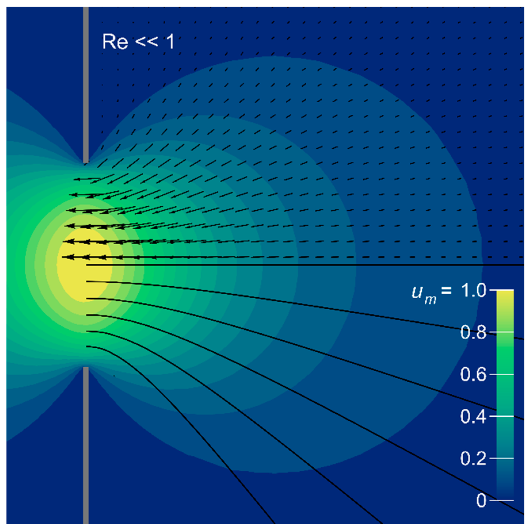
This flow field is plotted below with the same graphical conventions as Figure 4.
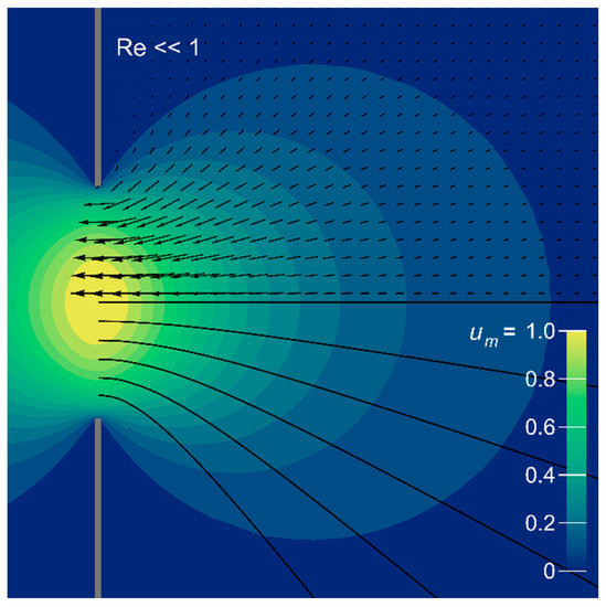
Figure A1.
Velocity field of creeping Sampson flow through a circular aperture in a flat plate (indicated schematically by a broken grey line). Magnitudes are represented by color contours, relative to the maximum at the center of the aperture, and are symmetric about the flow axis and wall plane. Flow direction is indicated by vectors and streamlines in black.
References
- Wainwright, P.C.; McGee, M.D.; Longo, S.J.; Patricia Hernandez, L. Origins, innovations, and diversification of suction feeding in vertebrates. Integr. Comp. Biol. 2015, 55, 134–145. [Google Scholar] [CrossRef]
- Longo, S.J.; McGee, M.D.; Oufiero, C.E.; Waltzek, T.B.; Wainwright, P.C. Body ram, not suction, is the primary axis of suction-feeding diversity in spiny-rayed fishes. J. Exp. Biol. 2016, 219, 119–128. [Google Scholar] [CrossRef] [PubMed]
- Westneat, M.W. Skull biomechanics and suction feeding in fishes. Fish Physiol. 2005, 23, 29–75. [Google Scholar] [CrossRef]
- Wainwright, P.C.; Ferry-Graham, L.A.; Waltzek, T.B.; Carroll, A.M.; Hulsey, C.D.; Grubich, J.R. Evaluating the use of ram and suction during prey capture by cichlid fishes. J. Exp. Biol. 2001, 204, 3039–3051. [Google Scholar] [PubMed]
- Holzman, R.; Day, S.W.; Mehta, R.S.; Wainwright, P.C. Jaw protrusion enhances forces exerted on prey by suction feeding fishes. J. R. Soc. Interface 2008, 5, 1445–1457. [Google Scholar] [CrossRef] [PubMed]
- Ferry-Graham, L.A.; Wainwright, P.C.; Lauder, G.V. Quantification of flow during suction feeding in bluegill sunfish. Zoology 2003, 106, 159–168. [Google Scholar] [CrossRef]
- Holzman, R.; Day, S.W.; Mehta, R.S.; Wainwright, P.C. Integrating the determinants of suction feeding performance in centrarchid fishes. J. Exp. Biol. 2008, 211, 3296–3305. [Google Scholar] [CrossRef][Green Version]
- Wainwright, P.; Carroll, A.M.; Collar, D.C.; Day, S.W.; Higham, T.E.; Holzman, R.A. Suction feeding mechanics, performance, and diversity in fishes. Integr. Comp. Biol. 2007, 47, 96–106. [Google Scholar] [CrossRef]
- Deban, S.M.; Olson, W.M. Biomechanics: Suction feeding by a tiny predatory tadpole. Nature 2002, 420, 41. [Google Scholar] [CrossRef]
- Stinson, C.M.; Deban, S.M. Functional trade-offs in the aquatic feeding performance of salamanders. Zoology 2017, 125, 69–78. [Google Scholar] [CrossRef]
- Marshall, C.D.; Kovacs, K.M.; Lydersen, C. Feeding kinematics, suction and hydraulic jetting capabilities in bearded seals (Erignathus barbatus). J. Exp. Biol. 2008, 211, 699–708. [Google Scholar] [CrossRef] [PubMed]
- Motta, P.J.; Hueter, R.E.; Tricas, T.C.; Summers, A.P.; Huber, D.R.; Lowry, D.; Mara, K.R.; Matott, M.P.; Whitenack, L.B.; Wintzer, A.P. Functional morphology of the feeding apparatus, feeding constraints, and suction performance in the nurse shark Ginglymostoma cirratum. J. Morphol. 2008, 269, 1041–1055. [Google Scholar] [CrossRef] [PubMed]
- Gordon, E.; Pacheco, S. Prey composition in the carnivorous plants Utricularia inflata and U. gibba (Lentibulariaceae) from Paria Peninsula, Venezuela. Rev. De Biol. Trop. 2007, 55, 795–803. [Google Scholar] [CrossRef] [PubMed]
- Harms, S. Prey selection in three species of the carnivorous aquatic plant Utricularia (bladderwort). Arch. Für Hydrobiol. 1999, 146, 449–470. [Google Scholar] [CrossRef]
- Day, S.W.; Higham, T.E.; Cheer, A.Y.; Wainwright, P.C. Spatial and temporal patterns of water flow generated by suction-feeding bluegill sunfish Lepomis macrochirus resolved by particle image velocimetry. J. Exp. Biol. 2005, 208, 2661–2671. [Google Scholar] [CrossRef]
- Leeuwen, J.v.; Muller, M. Optimum sucking techniques for predatory fish. J. Zool. 1984, 37, 137–169. [Google Scholar] [CrossRef]
- Carroll, A.M.; Wainwright, P.C.; Huskey, S.H.; Collar, D.C.; Turingan, R.G. Morphology predicts suction feeding performance in centrarchid fishes. J. Exp. Biol. 2004, 207, 3873–3881. [Google Scholar] [CrossRef]
- Higham, T.E.; Day, S.W.; Wainwright, P.C. The pressures of suction feeding: The relation between buccal pressure and induced fluid speed in centrarchid fishes. J. Exp. Biol. 2006, 209, 3281–3287. [Google Scholar] [CrossRef]
- Van Wassenbergh, S.; Aerts, P.; Herrel, A. Scaling of suction-feeding kinematics and dynamics in the African catfish, Clarias gariepinus. J. Exp. Biol. 2005, 208, 2103–2114. [Google Scholar] [CrossRef]
- Norton, S.F.; Brainerd, E.L. Convergence in the feeding mechanics of ecomorphologically similar species in the Centrarchidae and Cichlidae. J. Exp. Biol. 1993, 176, 11–29. [Google Scholar]
- Higham, T.E.; Day, S.W.; Wainwright, P.C. Multidimensional analysis of suction feeding performance in fishes: Fluid speed, acceleration, strike accuracy and the ingested volume of water. J. Exp. Biol. 2006, 209, 2713–2725. [Google Scholar] [CrossRef]
- Roos, G.; Van Wassenbergh, S.; Herrel, A.; Aerts, P. Kinematics of suction feeding in the seahorse Hippocampus reidi. J. Exp. Biol. 2009, 212, 3490–3498. [Google Scholar] [CrossRef] [PubMed]
- Holzman, R.; Collar, D.C.; Day, S.W.; Bishop, K.L.; Wainwright, P.C. Scaling of suction-induced flows in bluegill: Morphological and kinematic predictors for the ontogeny of feeding performance. J. Exp. Biol. 2008, 211, 2658–2668. [Google Scholar] [CrossRef]
- Muller, M.; Osse, J.; Verhagen, J. A quantitative hydrodynamical model of suction feeding in fish. J. Theor. Biol. 1982, 95, 49–79. [Google Scholar] [CrossRef]
- Aerts, P.; Osse, J.; Verraes, W. Model of jaw depression during feeding in Astatotilapia elegans (Teleostei: Cichlidae): Mechanisms for energy storage and triggering. J. Morphol. 1987, 194, 85–109. [Google Scholar] [CrossRef] [PubMed]
- Camp, A.L.; Roberts, T.J.; Brainerd, E.L. Swimming muscles power suction feeding in largemouth bass. Proc. Natl. Acad. Sci. USA 2015, 112, 8690–8695. [Google Scholar] [CrossRef]
- Camp, A.L.; Roberts, T.J.; Brainerd, E.L. Bluegill sunfish use high power outputs from axial muscles to generate powerful suction-feeding strikes. J. Exp. Biol. 2018, 221. [Google Scholar] [CrossRef]
- Van Wassenbergh, S.; Strother, J.A.; Flammang, B.E.; Ferry-Graham, L.A.; Aerts, P. Extremely fast prey capture in pipefish is powered by elastic recoil. J. R. Soc. Interface 2008, 5, 285–296. [Google Scholar] [CrossRef]
- Poppinga, S.; Weisskopf, C.; Westermeier, A.S.; Masselter, T.; Speck, T. Fastest predators in the plant kingdom: Functional morphology and biomechanics of suction traps found in the largest genus of carnivorous plants. Aob Plants 2016, 8. [Google Scholar] [CrossRef]
- Singh, A.K.; Prabhakar, S.; Sane, S.P. The biomechanics of fast prey capture in aquatic bladderworts. Biol. Lett. 2011. [Google Scholar] [CrossRef]
- Vincent, O.; Weißkopf, C.; Poppinga, S.; Masselter, T.; Speck, T.; Joyeux, M.; Quilliet, C.; Marmottant, P. Ultra-fast underwater suction traps. Proc. R. Soc. Lond. B Biol. Sci. 2011, 278, 2909–2914. [Google Scholar] [CrossRef] [PubMed]
- Westermeier, A.S.; Fleischmann, A.; Müller, K.; Schäferhoff, B.; Rubach, C.; Speck, T.; Poppinga, S. Trap diversity and character evolution in carnivorous bladderworts (Utricularia, Lentibulariaceae). Sci. Rep. 2017, 7, 12052. [Google Scholar] [CrossRef] [PubMed]
- Sasago, A.; Sibaoka, T. Water extrusion in the trap bladders of Utricularia vulgaris I. A possible pathway of water across the bladder wall. Bot. Mag. Tokyo 1985, 98, 55–66. [Google Scholar] [CrossRef]
- Sasago, A.; Sibaoka, T. Water extrustion in the trap bladders of Utricularia vulgaris II. A possible mechanism of water outflow. Bot. Mag. Tokyo 1985, 98, 113–124. [Google Scholar] [CrossRef]
- Adamec, L.; Poppinga, S. Measurement of the critical negative pressure inside traps of aquatic carnivorous Utricularia species. Aquat. Bot. 2016, 133, 10–16. [Google Scholar] [CrossRef]
- Sydenham, P.; Findlay, G. The rapid movement of the bladder of Utricularia sp. Aust. J. Biol. Sci. 1973, 26, 1115–1126. [Google Scholar] [CrossRef]
- Poppinga, S.; Daber, L.E.; Westermeier, A.S.; Kruppert, S.; Horstmann, M.; Tollrian, R.; Speck, T. Biomechanical analysis of prey capture in the carnivorous Southern bladderwort (Utricularia australis). Sci. Rep. 2017, 7, 1776. [Google Scholar] [CrossRef]
- Van Wassenbergh, S.; Roos, G.; Genbrugge, A.; Leysen, H.; Aerts, P.; Adriaens, D.; Herrel, A. Suction is kid’s play: Extremely fast suction in newborn seahorses. Biol. Lett. 2009, 5, 200–203. [Google Scholar] [CrossRef]
- Sanford, C.P.; Wainwright, P.C. Use of sonomicrometry demonstrates the link between prey capture kinematics and suction pressure in largemouth bass. J. Exp. Biol. 2002, 205, 3445–3457. [Google Scholar]
- Friday, L. The size and shape of traps of Utricularia vulgaris L. Funct. Ecol. 1991, 5, 602–607. [Google Scholar] [CrossRef]
- Reifenrath, K.; Theisen, I.; Schnitzler, J.; Porembski, S.; Barthlott, W. Trap architecture in carnivorous Utricularia (Lentibulariaceae). Flora-Morphol. Distrib. Funct. Ecol. Plants 2006, 201, 597–605. [Google Scholar] [CrossRef]
- Anto, J.; Majoris, J.; Turingan, R. Prey selection and functional morphology through ontogeny of Amphiprion clarkii with a congeneric comparison. J. Fish Biol. 2009, 75, 575–590. [Google Scholar] [CrossRef] [PubMed]
- Bremigan, M.T.; Stein, R.A. Gape-dependent larval foraging and zooplankton size: Implications for fish recruitment across systems. Can. J. Fish. Aquat. Sci. 1994, 51, 913–922. [Google Scholar] [CrossRef]
- Hernandez, L. Intraspecific scaling of feeding mechanics in an ontogenetic series of zebrafish, Danio rerio. J. Exp. Biol. 2000, 203, 3033–3043. [Google Scholar] [PubMed]
- Krebs, J.M.; Turingan, R.G. Intraspecific variation in gape–prey size relationships and feeding success during early ontogeny in red drum, Sciaenops ocellatus. Environ. Biol. Fishes 2003, 66, 75–84. [Google Scholar] [CrossRef]
- China, V.; Holzman, R. Hydrodynamic starvation in first-feeding larval fishes. Proc. Natl. Acad. Sci. USA 2014, 111, 8083–8088. [Google Scholar] [CrossRef]
- Pekkan, K.; Chang, B.; Uslu, F.; Mani, K.; Chen, C.-Y.; Holzman, R. Characterization of zebrafish larvae suction feeding flow using μPIV and optical coherence tomography. Exp. Fluids 2016, 57, 112. [Google Scholar] [CrossRef]
- Yaniv, S.; Elad, D.; Holzman, R. Suction feeding across fish life stages: Flow dynamics from larvae to adults and implications for prey capture. J. Exp. Biol. 2014, 217, 3748–3757. [Google Scholar] [CrossRef]
- True, A.C.; Crimaldi, J.P. Hydrodynamics of viscous inhalant flows. Phys. Rev. E 2017, 95, 053107. [Google Scholar] [CrossRef]
- Jumars, P.A. Boundary-trapped, inhalant siphon and drain flows: Pipe entry revisited numerically. Limnol. Oceanogr. Fluids Environ. 2013, 3, 21–39. [Google Scholar] [CrossRef]
- Szymanski, P. Quelques Solutions Exactes des Equations de 1′Hydrodynamique de Fluide Visqueux dans le Cas d’un Tube Cylindrique. J. Des Math. Pures Et Appl. 1932, 11, 67–107. [Google Scholar]
- Vrentas, J.; Duda, J. Flow of a Newtonian fluid through a sudden contraction. Appl. Sci. Res. 1973, 28, 241–260. [Google Scholar] [CrossRef]
- Berg, O.; Brown, M.D.; Schwaner, M.J.; Hall, M.R.; Müller, U.K. Hydrodynamics of the bladderwort feeding strike. J. Exp. Zool. Part A Ecol. Integr. Physiol. 2020. [Google Scholar] [CrossRef] [PubMed]
- Berg, O.; Singh, K.; Hall, M.R.; Schwaner, M.J.; Müller, U.K. Thermodynamics of the bladderwort feeding strike—Suction power from elastic energy storage. Integr. Comp. Biol. 2019. [Google Scholar] [CrossRef] [PubMed]
- Voesenek, C.J.; Muijres, F.T.; Van Leeuwen, J.L. Biomechanics of swimming in developing larval fish. J. Exp. Biol. 2018, 221, jeb149583. [Google Scholar] [CrossRef] [PubMed]
- Miller, L.A.; Peskin, C.S. When vortices stick: An aerodynamic transition in tiny insect flight. J. Exp. Biol. 2004, 207, 3073–3088. [Google Scholar] [CrossRef] [PubMed]
- Birch, J.M.; Dickson, W.B.; Dickinson, M.H. Force production and flow structure of the leading edge vortex on flapping wings at high and low Reynolds numbers. J. Exp. Biol. 2004, 207, 1063–1072. [Google Scholar] [CrossRef]
- China, V.; Levy, L.; Liberzon, A.; Elmaliach, T.; Holzman, R. Hydrodynamic regime determines the feeding success of larval fish through the modulation of strike kinematics. Proc. R. Soc. B Biol. Sci. 2017, 284, 20170235. [Google Scholar] [CrossRef]
- Drost, M.; Muller, M.; Osse, J. A quantitative hydrodynamical model of suction feeding in larval fishes: The role of frictional forces. Proc. R. Soc. B: Biol. Sci. 1988, 234, 263–281. [Google Scholar]
- D’Amato, P. The Savage Garden, Revised: Cultivating Carnivorous Plants; Ten Speed Press: Berkeley, CA, USA, 2013. [Google Scholar]
- Thielicke, W.; Stamhuis, E. PIVlab–towards user-friendly, affordable and accurate digital particle image velocimetry in MATLAB. J. Open Res. Softw. 2014, 2. [Google Scholar] [CrossRef]
- Raffel, M.; Willert, C.E.; Wereley, S.T.; Kompenhans, J. Particle Image Velocimetry: A Practical Guide; Springer: Berlin/Heidelberg, Germany, 1998; p. 255. [Google Scholar]
- Westerweel, J. Fundamentals of digital particle image velocimetry. Meas. Sci. Technol. 1997, 8, 1379. [Google Scholar] [CrossRef]
- Sampson, R.A., XII. On Stokes’s current function. Philos. Trans. R. Soc. London 1891, 449–518. [Google Scholar] [CrossRef]
- Dagan, Z.; Weinbaum, S.; Pfeffer, R. An infinite-series solution for the creeping motion through an orifice of finite length. J. Fluid Mech. 1982, 115, 505–523. [Google Scholar] [CrossRef]
- Weissberg, H.L. End correction for slow viscous flow through long tubes. Phys. Fluids 1962, 5, 1033–1036. [Google Scholar] [CrossRef]
- Thompson, B.; Maynes, D.; Webb, B. Characterization of the hydrodynamically developing flow in a microtube using MTV. J. Fluids Eng. 2005, 127, 1003–1012. [Google Scholar] [CrossRef]
- Durst, F.; Loy, T. Investigations of laminar flow in a pipe with sudden contraction of cross sectional area. Comput. Fluids 1985, 13, 15–36. [Google Scholar] [CrossRef]
© 2020 by the authors. Licensee MDPI, Basel, Switzerland. This article is an open access article distributed under the terms and conditions of the Creative Commons Attribution (CC BY) license (http://creativecommons.org/licenses/by/4.0/).

