Article

Full-Span Flying Wing Wind Tunnel Test: A Body Freedom Flutter Study

1
School of Aeronautics, Northwestern Polytechnical University, Xi’an 710072, Shaanxi, China
2
General Design Department, Sichuan Academy of Aerospace Technology, Chengdu 610100, Sichuan, China
3
School of Engineering, RMIT University, Bundoora, VIC 3083, Australia
*
Authors to whom correspondence should be addressed.
Fluids 2020, 5(1), 34; https://doi.org/10.3390/fluids5010034
Submission received: 31 January 2020 / Revised: 25 February 2020 / Accepted: 10 March 2020 / Published: 16 March 2020
(This article belongs to the Special Issue Flow and Aeroelastic Control)

Abstract

:
Aiming at the experimental test of the body freedom flutter for modern high aspect ratio flexible flying wing, this paper conducts a body freedom flutter wind tunnel test on a full-span flying wing flutter model. The research content is summarized as follows: (1) The full-span finite element model and aeroelastic model of an unmanned aerial vehicle for body freedom flutter wind tunnel test are established, and the structural dynamics and flutter characteristics of this vehicle are obtained through theoretical analysis. (2) Based on the preliminary theoretical analysis results, the design and manufacturing of this vehicle are completed, and the structural dynamic characteristics of the vehicle are identified through ground vibration test. Finally, the theoretical analysis model is updated and the corresponding flutter characteristics are obtained. (3) A novel quasi-free flying suspension system capable of releasing pitch, plunge and yaw degrees of freedom is designed and implemented in the wind tunnel flutter test. The influence of the nose mass balance on the flutter results is explored. The study shows that: (1) The test vehicle can exhibit body freedom flutter at low airspeeds, and the obtained flutter speed and damping characteristics are favorable for conducting the body freedom flutter wind tunnel test. (2) The designed suspension system can effectively release the degrees of freedom of pitch, plunge, and yaw. The flutter speed measured in the wind tunnel test is 9.72 m/s, and the flutter frequency is 2.18 Hz, which agree well with the theoretical results (with flutter speed of 9.49 m/s and flutter frequency of 2.03 Hz). (3) With the increasing of the mass balance at the nose, critical speed of body freedom flutter rises up and the flutter frequency gradually decreases, which also agree well with corresponding theoretical results.

1. Introduction

The high aspect ratio flexible flying wing (HARFFW) is a quite favorable configuration in unmanned aerial vehicle (UAV) development because of its excellent aerodynamic performance. Usually, the rigid body pitch mode frequency of the flying wing will increase due to the tailless design, and the elastic modal frequency decreases due to the aspect ratio and flexibility of the wing increases. The coupling of the short period pitch mode with the wing elastic mode will result in a special type of aeroelastic instability problem, which is called body freedom flutter (BFF). There are two folds of hazards coming from the BFF: (1) When dynamic pressure is lower than the flutter boundary, the handling quality of the aircraft will be adversely affected by the elastic mode of the wing. (2) Once the dynamic pressure is reaching the flutter boundary, the aircraft will undergo severe pitching oscillations and diverging wing bending motion, leading to a catastrophic aircraft failure.
Theoretical analysis methods for the BFF problem include classical frequency domain method [1], state space method [2], robust modeling and analysis framework research method [3], fully coupled linearization method under aeroelastic trimming conditions [4]. The theoretical analysis of BFF shows that for the HARFFW, the BFF speed is significantly lower than that results calculated based on the cantilever wing model; the elastic degrees of freedom of the aircraft, the structural characteristics of the fuselage and the wing structure characteristics will have significant impact on the BFF characteristics.
Since the BFF problem may affect the flight dynamics of flexible configuration with large aspect ratio or large slender ratio, several modeling schemes for this special configuration are developed. Comprehensive theoretical models [5] are established regarding flight dynamics and aeroelasticity coupled with large body movement and small elastic deformation. Moreover, improved aeroelastic analysis method are developed considering additional terms, i.e., the influence of unsteady aerodynamic force and gravity, combing with the control system [6]. High fidelity aeroelastic simulation analysis is also studied by implementing the computational fluid dynamics (CFD) method [7]. More recently, flight dynamics model considering elastic effect are developed based on mean axis motion equation [8]. The research on the multi-disciplinary optimization framework for the solar powered high altitude long endurance (HALE) UAV shows that the design of HALE aircraft is mainly subject to the stiffness constraints, which is different from the strength constraints of the traditional aircraft.
Beside the theoretical analysis, the BFF test, including wind tunnel and flight flutter test, are also quite complex elements of the testing campaign. Comprehensive experimental validation studies of BFF usually include the design and processing of the flexible flying wing aircraft and the formulation of the test scheme [9,10], updating of theoretical analysis model by ground vibration test [11], and verification of theoretical analysis by wind tunnel test [12]. When the theoretical model is updated according to the ground vibration test data, the accuracy of model modification can be improved by optimization algorithm according to the complexity of the model. One should pay close attention to the influence of model support system on the test results in wind tunnel test.
In recent years, the X-56A multi-utility technology test bed (MUTT) [6], which is used to study the BFF and active flutter suppression of BFF vehicle, has completed the flight dynamics simulation and aeroelastic simulation, the aeroelastic modeling method is verified through the flight test data [7]. Based on the scaled model of X-56A MUTT, BFF vehicle conceptual design [8,9], theoretical modeling and analysis [13,14] and active flutter suppression controller design [15,16,17,18] studies have been completed and verified by closed-loop flight tests have been carried out [19,20].
The traditional wind tunnel test include hard supporting fixtures [21,22], including abdominal support, tail support, back support [23], etc. With the development of mechanism technology, parallel support system and rope traction support system have emerged [24,25,26]. However, for the BFF wind tunnel test, it is necessary to release the rigid body freedom of the model to simulate the “free flight” state, especially the pitch and plunge degrees of freedom. In the BFF wind tunnel test for flying wing half model, there are side wall track support system [27], a lateral support system installed at the bottom of the wind tunnel [28]; in the wind tunnel test using full-span model, there are beam support system [29] and flexible support system [30].
To the best of the authors’ knowledge, there is no public report available on the body freedom flutter wind tunnel test of the full-span flying wing model which is capable of free flying. In this work, a BFF flying wing UAV model is designed and a novel quasi-free-flying support system is introduced into the full-span BFF wind tunnel test.
The rest of the paper is organized as follows. In Section 2, the basic theory of BFF analysis is introduced. In Section 3, the structural finite element method (FEM) modeling and aeroelastic modeling of the UAV along with the BFF wind tunnel test are introduced, and the preliminary theoretical analysis is conducted. In Section 4, the design and processing of UAV are completed, and the theoretical analysis model is modified by the ground vibration test. In Section 5, the quasi-free-flying suspension system design and the comparison between the test and theoretical results are supplied; in the final Section, the overall work is summarized and pertinent conclusions are drawn.

2. Theory of Aeroelastic Modeling

2.1. Structural Dynamics

For a n-degree of freedom (DOF) system [31], define n generalized coordinates q 1 , q 2 , , q n , the displacement of any point in the system can be expressed as:
r = r ( q 1 , q 2 , , q n , t )
For the wing located in xoy plane, as shown in Figure 1, the normal motion of the wing will cause additional unsteady aerodynamic force, the normal displacement expanded in the modal space is written as:
z a = m q m t z m x , y
Then the kinetic energy of the system is casted as:
T = 1 2 m n q ˙ m q ˙ n M m n
where the generalized mass is presented as:
M m n = m z m z n d x d y
Selecting the modal coordinates that satisfies the following normalization conditions:
M m n = M m δ m n , δ m n = 0 , m n 1 , m = n
Equation (3) can be written as:
T = 1 2 m q ˙ m 2 M m
Similarly, the elastic potential energy of the wing structure in the modal coordinate is:
U = 1 2 m n q m q n K m n
where K m n is the generalized stiffness matrix.
Using the modal coordinates satisfying the normalization condition, one can write:
K m n = ω m 2 M m n δ m n
where ω m is the mth order natural frequency.
The potential energy and kinetic energy of the system obtained above are substituted into the Lagrange equation:
d d t T U q ˙ i + T U q i + Q i = 0 i = 1 , 2 ,
Thus, the equations of motion of the wing structure can be obtained.

2.2. Doublet Lattice Method (DLM) for Unsteady Aerodynamics

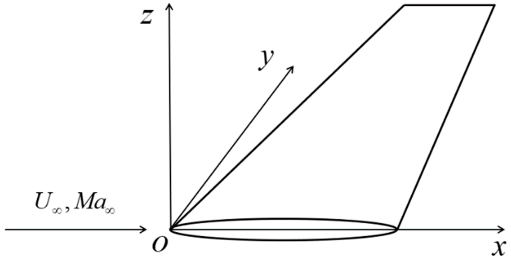
For the flat wing as shown in Figure 2, the Euler method is used to describe the aerodynamic motion characteristics at any point in the flow field. The wing is located in the xoy plane, the positive direction of the x-axis is consistent with the far-field flow direction, the y-axis is pointing to the right, and the z-axis is determined according to the right-hand rule.
For the flutter problem, small amplitude structural vibration based on the static deformation is considered. The small disturbance hypothesis is well accepted as the motion induced velocity and pressure of the flow disturbance are small compared with the those of the far-field flow. Usually, the critical flutter stability condition corresponds to a simple harmonic motion [32]. For harmonic oscillation, the linear small disturbance velocity potential equation is written as:
1 M a 2 2 φ 2 x + 2 φ 2 y + 2 φ 2 z 2 i M a 2 k b φ x + M a 2 k 2 b 2 φ = 0
in the frequency domain, where k is the reduced frequency, and its expression is:
k = b ω V
where b is the reference length and ω is the circular frequency, respectively.
The subsonic DLM is a panel method based on the linear velocity potential equation of small disturbance, Equation (10). The lifting surface is divided into a number of aerodynamic grids, as shown in Figure 3. The aerodynamic force acts at the midpoint of the 1/4 chord line on each grid element, which is called the pressure point (F2 point in Figure 3); the midpoint of the 3/4 chord line is called the control point (H point in Figure 3). The boundary conditions at these control points are met due to the amplitude of the normal downwash velocity generated by the proper doublet line distribution.
Suppose that the lifting surface is divided into n grids, and the pressure difference Δ p on each grid is a constant, pressure doublets are arranged at the pressure points of each grid. According to the theory of linear unsteady aerodynamics, the integral equation is satisfied at the downwash control point of each aerodynamic grid:
w i = 1 4 π ρ V 2 j = 1 n 1 2 ρ V 2 Δ c p j Δ x j cos ϕ j l j K i j d l j = 1 8 π j = 1 n Δ c p j Δ x j cos ϕ j l j K i j d l j i = 1 , 2 , , n ; j = 1 , 2 , , n
where
  • w i —The downwash at the 3/4 chord length point of the ith grid
  • Δ c p j —The pressure coefficient on the jth grid, has the following relationship with the pressure difference Δ p j : Δ c p j = 2 Δ p j ρ V 2
  • Δ x j —Mid section length of the jth grid
  • l j —Length at 1/4 chord F 1 F 3 ¯ of the jth grid
  • φ j —the sweepback angle at 1/4 chord F 1 F 3 ¯ of the jth grid
  • K i j —Aerodynamic kernel function
The unsteady aerodynamic pressure distribution at the pressure point is written in matrix form as:
Δ p = 1 2 ρ V 2 D 1 w
where
  • Δ p is pressure distribution vector at the point of pressure action
  • w is the downwash vector at the downwash control point
  • D is the aerodynamic influence coefficient matrix
Assuming that the structure is under a small deformation motion, and n-order vibration modes are considered, and the modal expansion is used to express its vibration motion, then the normal displacement of any point of the structure can be expressed as:
z = F q
where q is the generalized coordinate vector and F is the modal matrix.
For a thin airfoil, the boundary condition is satisfied at the H-point, so hence relationship between the downwash velocity of each aerodynamic grid H-point and the vibration mode coordinate is:
w = F + i k b F q
where F is the derivative of matrix F with respect to x at point H.
The expression of unsteady aerodynamic pressure distribution in frequency domain is:
Δ p = P q
where P is the pressure coefficient matrix, and the expression is:
P = 1 2 ρ V 2 D 1 F + i k b F
Frequency domain aerodynamics can be calculated by DLM, which is directly used by p-k method to perform flutter calculation.

3. Preliminary Modeling and Analysis of BFF Wind Tunnel Test UAV

In this section, a full-span FEM and an aeroelastic model of the BFF wind tunnel test UAV are established. The structural dynamics and flutter characteristics are obtained through theoretical analysis.

3.1. Modeling and Analysis of Structural Dynamics

In order to simplify the structural design, the BFF wind tunnel test UAV uses a single-beam wing, and the main beam is made by carbon fiber composite material. To reduce the structural weight and additional stiffness, both the fuselage and the wing are made of foam material. A full-span FEM is established as shown in Figure 4. The detailed parameters of the UAV are summarized in Table 1.
In this FEM, beam element is used to model the carbon fiber composite spar. Because of the slenderness of the spar, the carbon fiber composite is simplified to an isotropic beam for modeling purpose. To facilitate the observation of the modal shapes, a set of weightless rigid beam elements are connected to the main spar. In addition, the mass characteristics of airborne equipment are modeled by concentrated mass elements.
The structural dynamic characteristics are analyzed under free-free boundary conditions, and the first three elastic modes of the UAV are obtained. The modal frequencies are summarized in Table 2, and the corresponding mode shapes are shown in Figure 5.

3.2. Aeroelastic Modelling and Analysis

According to the requirements of the DLM for the division of the aerodynamic panel mesh, a full-span aerodynamic lifting surface model, as shown in Figure 6, is established for unsteady aerodynamic calculations.
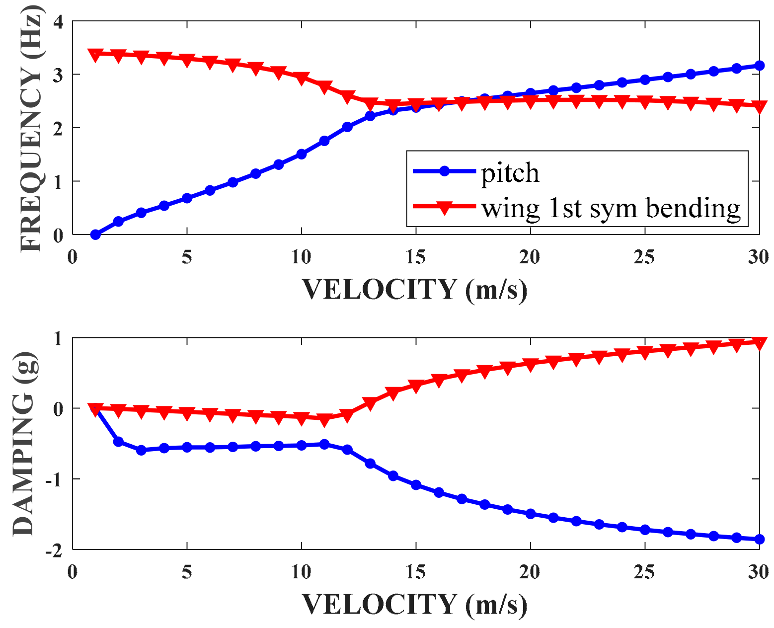
An aeroelastic model is established by using spline interpolation between aerodynamic lifting surface model and structural FEM, and flutter analysis is performed using p-k method. The flutter characteristics of this UAV obtained initially are shown in Figure 7. For the convenience of observation, only the v-g and v-f curves of rigid body pitch mode and wing symmetric first bending mode branch are given.
It can be seen from Figure 7 that as the airspeed increases, the frequency of the pitch mode gradually increases, and the frequency of wing symmetric first bending mode gradually decreases. When the airspeed reaches 12.52 m/s, the wing symmetric first bending mode’s damping changes from negative to positive, which represents flutter at this point. The flutter frequency is 2.53 Hz. The flutter is caused by the coupling of pitch mode and wing first symmetric bending mode, which is a classical BFF.

4. Ground Vibration Test and Model Updating

Based on the results of the preliminary theoretical analysis in Section 3, this Section completes the design and process followed to perform the BFF wind tunnel test UAV. Then, the structural dynamic characteristics of the UAV are identified through ground vibration test. Finally, based on the results of ground vibration test (GVT), theoretical analysis model is updated and the revised aeroelastic characteristics are obtained.

4.1. Design and Manufacture of the BFF Wind Tunnel Test UAV

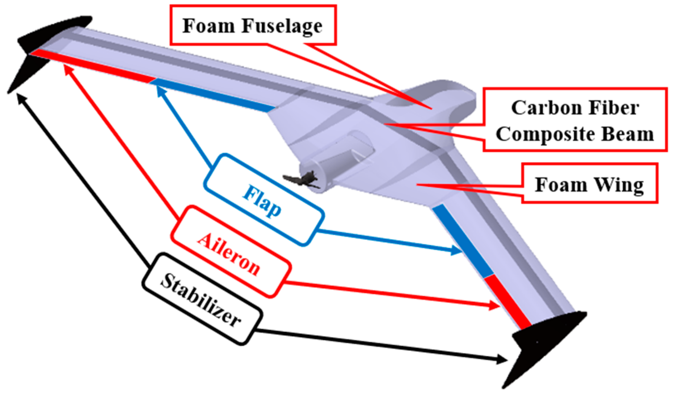
The computer aided design (CAD) model of BFF wind tunnel test UAV designed by Catia software is shown in Figure 8. The beam of this UAV is made by carbon fiber composite material. In order to reduce additional mass and additional stiffness, the fuselage and wings are made of foam, and the wings are partition off and then glued to the main beam. The UAV includes two sets of control surfaces. The inside flaps are used to introduce a sudden aerodynamic disturbance during the wind tunnel test to trigger the UAV pitching motion, while the outside ailerons are used for attitude control. In addition, to ensure the directional stability of the UAV, a pair of aerodynamically streamlined panels are located at the tip of the wing as stabilizer surfaces.
Based on the CAD model, parts processing and complete assembly of the UAV are carried out. The wing is formed using foam thermal cutting technology. After that, it is glued to the main beam as shown in Figure 9.
The completed UAV assembly is shown in Figure 10, and considering the future BFF flight test and active flutter suppression test, the airborne equipment shown in Figure 10 is used in the following test.

4.2. Ground Vibration Test

The structural dynamic characteristics of the BFF wind tunnel test UAV were attained by performing a ground vibration test on the UAV by hammer impact method. A single-point spring suspension is used to simulate the free boundary. A Siemens LMS Scadas XS system is used for data acquisition. The adopted accelerometer arrangement and ground vibration test setting are shown in Figure 11.
The first three elastic modal frequencies of the UAV obtained from the ground vibration test are summarized in Table 3. The corresponding mode shapes are shown in Figure 12. For ease of observation, the displayed mode shapes are mainly beam mode, the fuselage is simplified into a diamond-shaped plane.

4.3. Theoretical Analysis Model Updating

Based on the results of GVT, the theoretical analysis model is updated. The main modified parameter is the elastic modulus of the UAV’s spar. The revised theoretical analysis result of structural dynamics and the test results are compared in Table 4.
It can be seen that the experimental and theoretical analysis results agree well, indicating that the structured FEM can accurately reflect the structural dynamics of the UAV, and based on this model, a reliable flutter solution can be obtained.
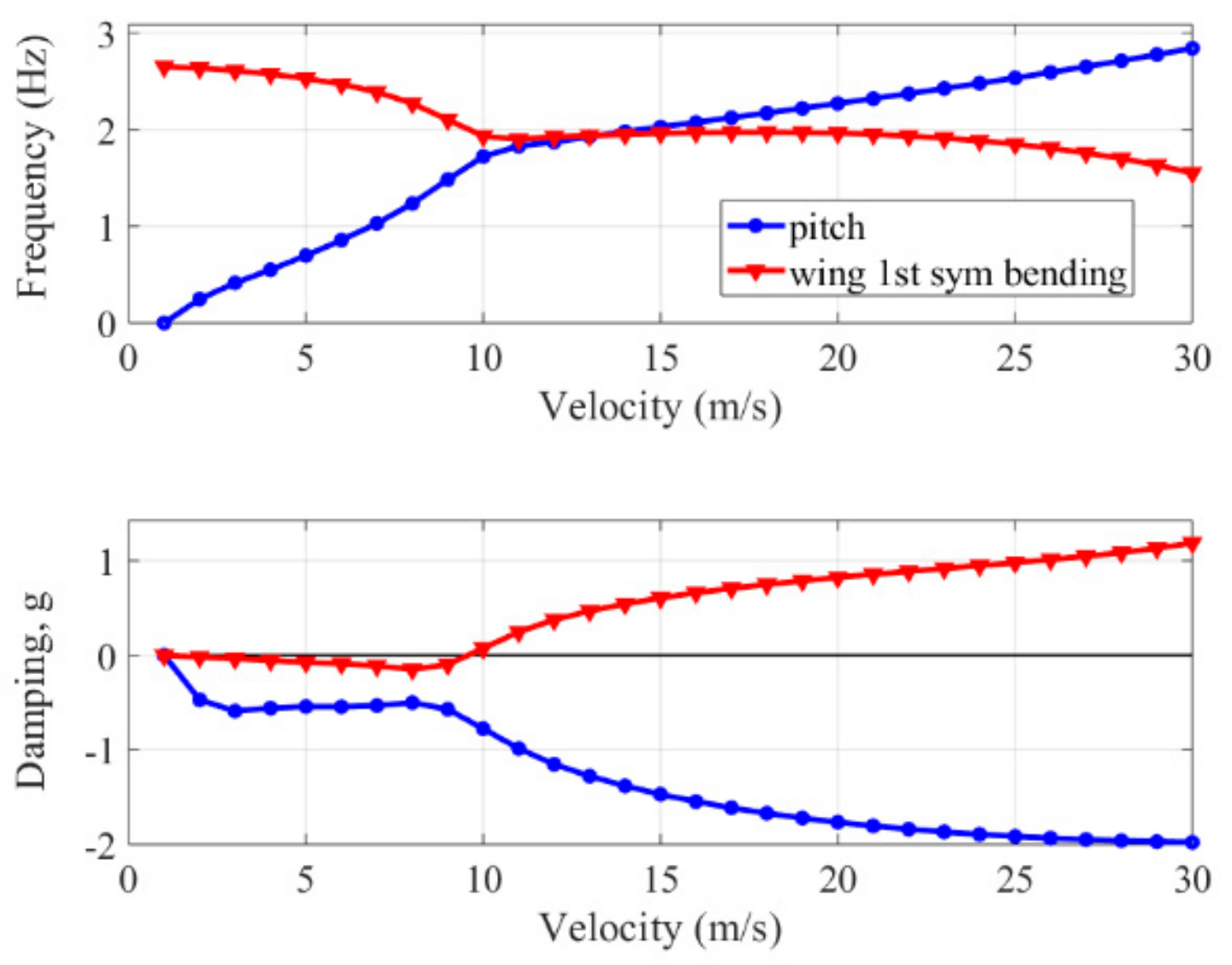
The flutter characteristics are re-calculated using the updated theoretical analysis model, and the revised flutter speed and frequency of this UAV are shown in Figure 13.
After the parameter updating, a BFF flutter speed of 9.49 m/s and a flutter frequency of 2.03 Hz are obtained. The flutter speed and damping characteristics are suitable for conducting a BFF experiment in the wind tunnel.

5. Body Freedom Flutter Wind Tunnel Test

In this Section, a suspension system for BFF wind tunnel tests is designed, which can release the degrees of freedom in pitch, plunge, and yaw directions. Then, the suspension system is used to conduct the BFF UAV wind tunnel test. Finally, the influence of mass balance at the nose on BFF results is explored in the further wind tunnel test.

5.1. Suspension System Design

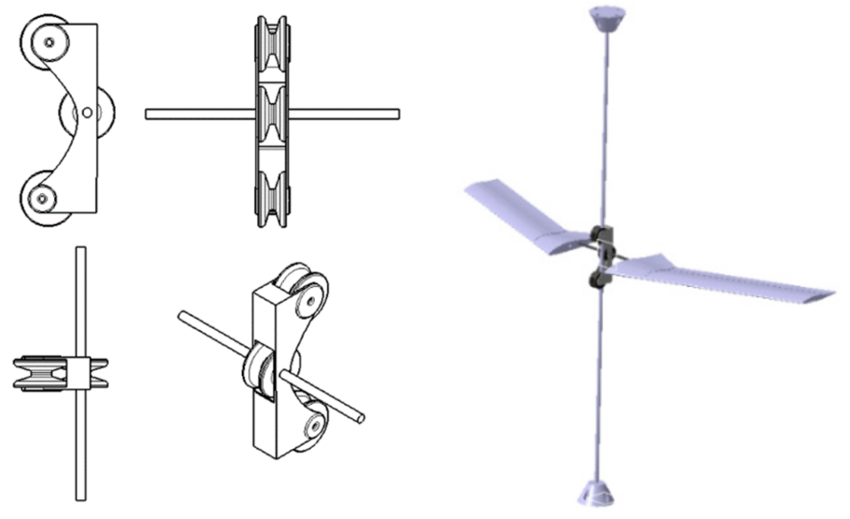
To release the rigid body DOF of the BFF UAV and reduce the wind tunnel test error, a suspension system for the BFF wind tunnel test of the full-span high aspect ratio flexible flying is designed. As shown in Figure 14, the system consists of tightwire and pulley set, which can effectively release the pitch, plunge and yaw freedom of the model, and simulate the free flight state of the UAV to the greatest extent.
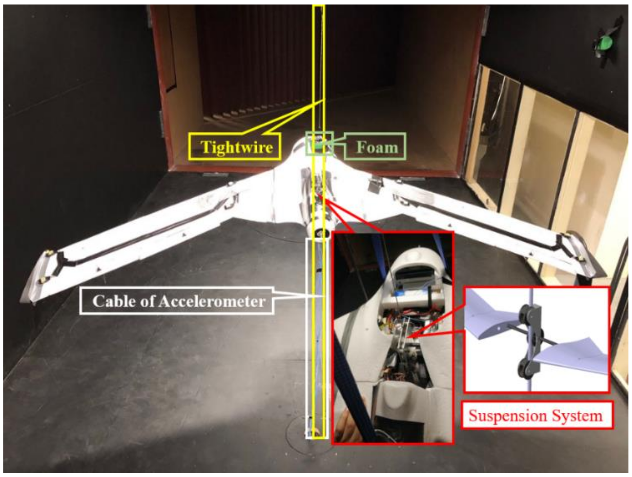
The wind tunnel test arrangement with this suspension system is shown in Figure 15. The accelerometer layout used in the wind tunnel test is consistent with the ground vibration test. During the wind tunnel test, a dampening sponge block is added in the plunge direction of UAV as a limiting device in case of violent oscillations. When the BFF is divergent, this arrangement can limit the UAV’s movement and provide protection, in case the UAV destroys or causes damage to the wind tunnel.

5.2. Body Freedom Flutter Wind Tunnel Test

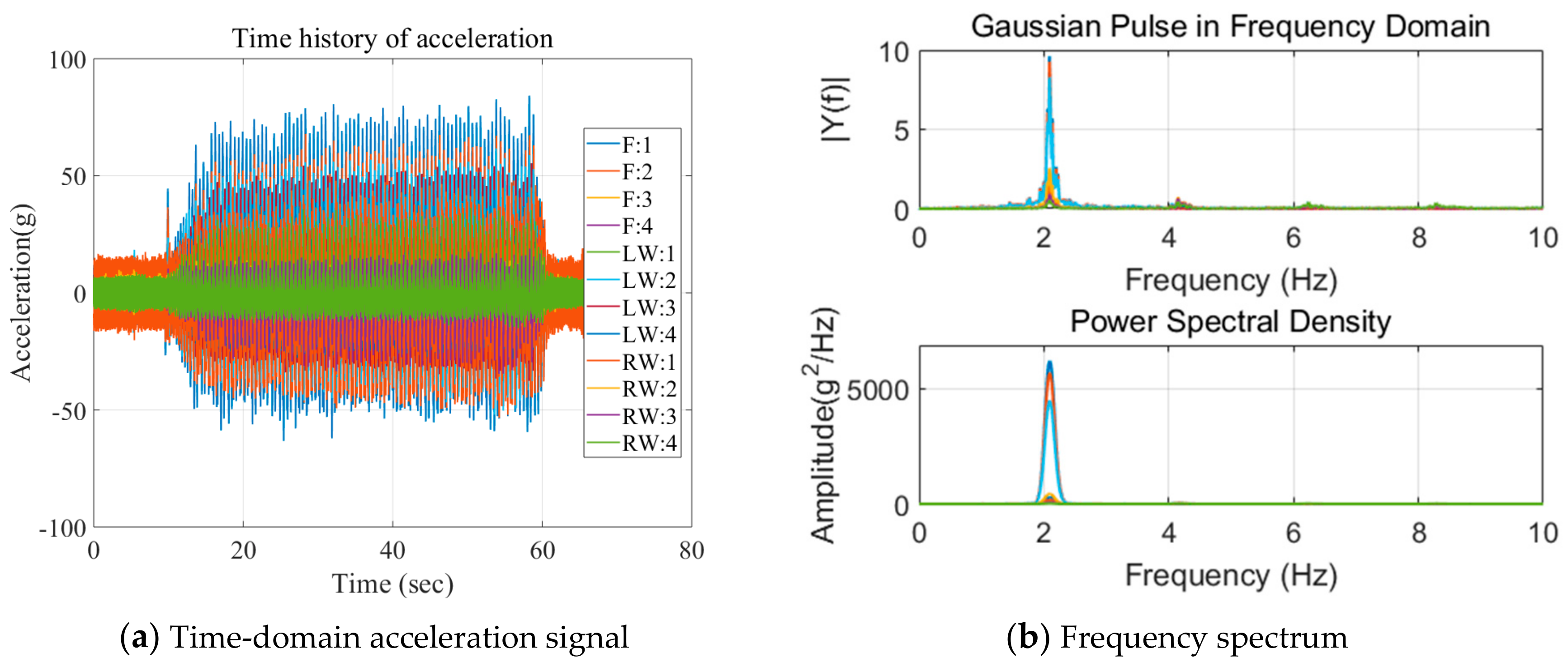
The wind tunnel test arrangement shown in Figure 15 is used to conduct BFF wind tunnel test under free-flight conditions. During the test, wind speed is continuously adjusted. A flap is used to excite the UAV when the airspeed stabilized. At 9.72 m/s, a typical BFF phenomenon is observed. The time-domain acceleration signal during flutter generation is collected, as shown in Figure 16a, the corresponding frequency spectrum is shown in Figure 16b. The flutter motion is as shown in Figure 17. The comparison of wind tunnel test results and theoretical analysis are summarized in Table 5. It can be seen that the theoretical results agree well with the test results.

5.3. Effect of Mass Balance at Nose on Characteristics of BFF

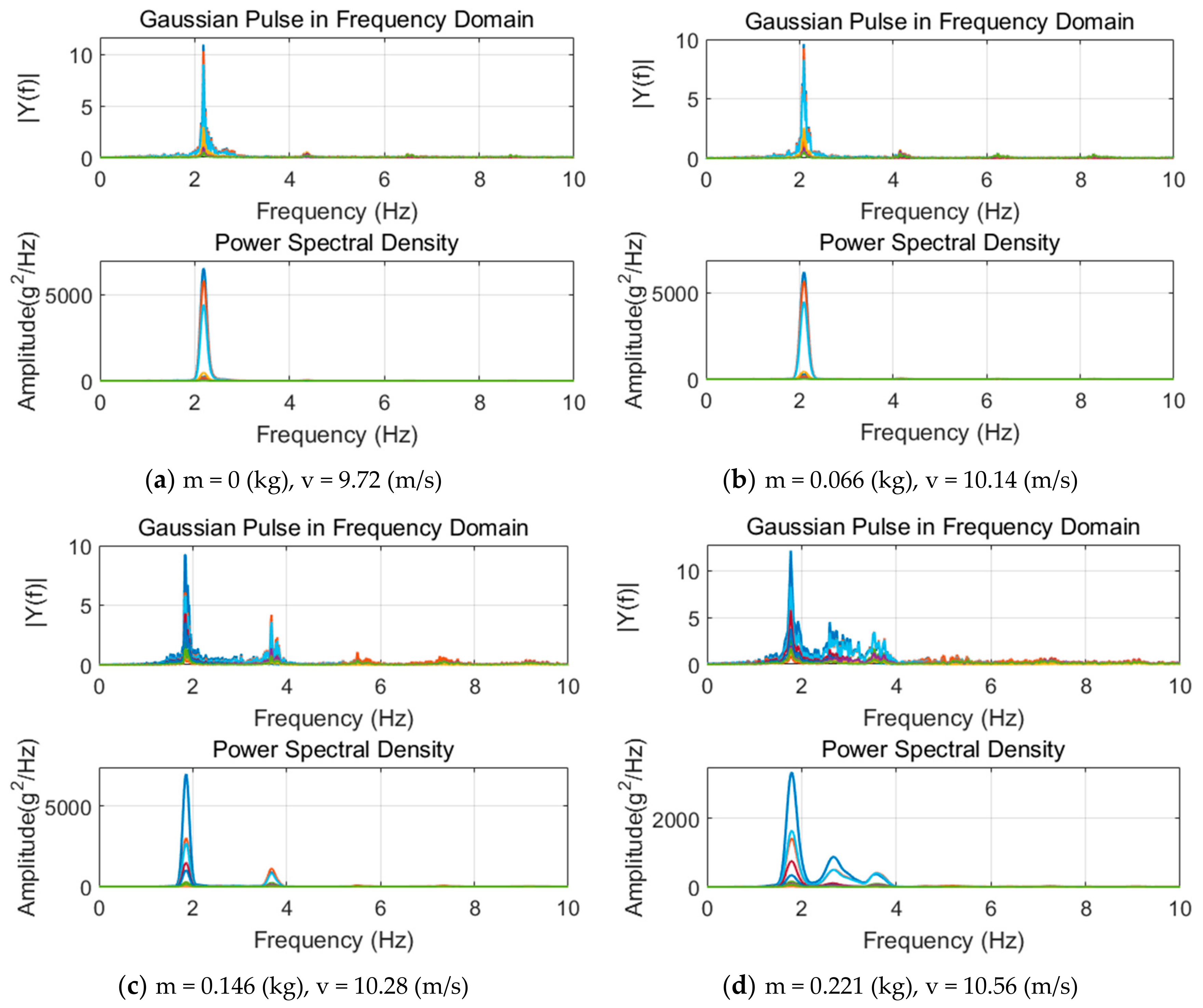
By gradually increasing the mass balance at nose of the UAV, it is also possible to explore the mass effect on BFF characteristics. The wind tunnel test result and the analyzed result are compared and summarized in Table 6. The time-domain acceleration signal and the corresponding frequency spectrum are shown in Figure 18. The results show that as the mass balance at nose increases, the flutter speed gradually increases, and the flutter frequency gradually decreases. The analyzed results show similar trend as expected.
By increasing the mass balance at nose leads to an increase in the pitch moment of inertia. This knowledge can be used to optimize the weight distribution of the aircraft. Indeed, with a small increase in the fuselage mass, which can improve the pitch moment of inertia, an increase in the flutter boundary of BFF can be observed.

6. Conclusions

In this paper, the body freedom flutter of a full-span flying wing is studied through theoretical analysis and wind tunnel tests. Comprehensive investigations including structural dynamic modeling and analysis, aeroelastic modeling and analysis, ground vibration test, model updating and quasi-free-flying BFF wind tunnel test are completed. Pertinent conclusions can be drawn as follows:
(1)
The theoretical analysis results show that the BFF wind tunnel test UAV can encounter BFF at low airspeed, which is suitable for performing BFF wind tunnel test.
(2)
The modal characteristics of updated FEM agree well with the ground vibration test results, indicating that the revised theoretical analysis model can accurately reflect the structural dynamic characteristics of the UAV.
(3)
Comparison of the wind tunnel test and theoretical analysis results shows that they agree well, indicating that the designed quasi-free-flying suspension system can effectively guarantee the test accuracy in wind tunnel BFF test.
(4)
Increasing the mass balance at nose of the flying wing leads to an increase in the pitch moment of inertia, which in turn increases the BFF boundary.

Author Contributions

Data curation, P.S. and J.L.; supervision, Y.G., Z.Y. and P.M.; writing—original draft, P.S.; writing—review and editing, Y.G. All authors have read and agreed to the published version of the manuscript.

Funding

This work was supported by the National Natural Science Foundation of China (Grant Nos. 11672240 and 11102162), “Science & Technology Innovation and Entrepreneurship Co-advisor Program” of Shaanxi Province, and Natural Science Basic Research Plan in Shaanxi Province of China (Program No. 2019JM-582).

Acknowledgments

The authors would like to acknowledge the support of RMIT University staff, in particular Paul Muscat (composite laboratory) and Matthew Marino and Gil Atkin (industry wind tunnel).

Conflicts of Interest

The authors declare no conflicts of interest.

References

  1. Banerjee, J.R. Flutter characteristics of high aspect ratio tailess aircraft. J. Aircr. 1984, 21, 733–736. [Google Scholar] [CrossRef]
  2. Moreno, C.P.; Seiler, P.J.; Balas, G.J. Model Reduction for Aeroservoelastic Systems. J. Aircr. 2014, 51, 280–290. [Google Scholar] [CrossRef] [Green Version]
  3. Iannelli, A.; Marcos, A.; Lowenberg, M. Study of Flexible Aircraft Body Freedom Flutter with Robustness Tools. J. Guid. Control Dyn. 2018, 41, 1083–1094. [Google Scholar] [CrossRef] [Green Version]
  4. Saltari, F.; Riso, C.; Matteis, G.D.; Mastroddi, F. Finite-Element-Based Modeling for Flight Dynamics and Aeroelasticity of Flexible Aircraft. J. Aircr. 2017, 54, 2350–2366. [Google Scholar] [CrossRef]
  5. Riso, C.; Mastroddi, F.; Cesnik, C.E.S. Coupled flight dynamics and aeroelasticity of very flexible aircraft based on commercial finite element solvers. In Proceedings of the AIAA/ASCE/AHS/ASC Structures, Structural Dynamics, and Materials Conference, Kissimmee, FL, USA, 8–12 January 2018. [Google Scholar]
  6. Ouellette, J.A. Aeroservoelastic Modeling of Body Freedom Flutter for Control System Design. In Proceedings of the AIAA Atmospheric Flight Mechanics Conference, Denver, CO, USA, 5 June 2017. [Google Scholar]
  7. Reasor, D.A.; Bhamidipati, K.K.; Chin, A.W. X-56A Aeroelastic Flight Test Predictions. In Proceedings of the 54th AIAA Aerospace Sciences Meeting, San Diego, CA, USA, 4–8 January 2016. [Google Scholar]
  8. Gupta, R.; Love, N.J.; Kapania, R.K.; Schmidt, D.K. Development of a flight dynamics analysis framework for inclusion into the MDAO process. In Proceedings of the 19th AIAA/ISSMO Multidisciplinary Analysis and Optimization Conference, Atlanta, GA, USA, 25–29 June 2018. [Google Scholar]
  9. Regan, C.D. mAEWing2: Conceptual Design and System Test. In Proceedings of the AIAA Atmospheric Flight Mechanics Conference, Grapevine, TX, USA, 9–13 January 2017. [Google Scholar]
  10. Beranek, J.; Nicolai, L.; Buonanno, M.; Burnett, E.; Atkinson, C.; Holm-Hansen, B.; Flick, P. Conceptual design of a multi-utility aeroelastic demonstrator. In Proceedings of the 13th AIAA/ISSMO Multidisciplinary Analysis and Optimization Conference (MAO), Fort Worth, TX, USA, 13–15 September 2010. [Google Scholar]
  11. Gupta, A.; Moreno, C.P.; Pfifer, H.; Taylor, B.; Balas, G.J. Updating a finite element based structural model of a small flexible aircraft. In Proceedings of the AIAA Modeling and Simulation Technologies Conference, Dallas, TX, USA, 22–26 June 2015. [Google Scholar]
  12. Liu, J.; Gu, Y.; Xie, K.; Shi, P. Flutter Modeling, Analysis and Test for Blended-Wing-Body Flying Wing. In Proceedings of the 2018 Asia-Pacific International Symposium on Aerospace Technology, Chengdu, Sichuan, China, 16–18 October 2018. [Google Scholar]
  13. Schmidt, D.K.; Zhao, W.; Kapania, R.K. Flight-dynamics and flutter modeling and analysis of a flexible flying-wing drone. In Proceedings of the AIAA Atmospheric Flight Mechanics Conference, San Diego, CA, USA, 4–8 January 2016. [Google Scholar]
  14. Schmidt, D.K. MATLAB-Based Flight-Dynamics and Flutter Modeling of a Flexible Flying-Wing Research Drone. J. Aircr. 2016, 53, 1045–1055. [Google Scholar] [CrossRef] [Green Version]
  15. Theis, J.; Pfifer, H.; Seiler, P.J. Robust Control Design for Active Flutter Suppression. In Proceedings of the AIAA Atmospheric Flight Mechanics Conference, San Diego, CA, USA, 4–8 January 2016. [Google Scholar]
  16. Danowsky, B.P.; Schmidt, D.K.; Pfifer, H. Control-Oriented System and Parameter Identification of a Small Flexible Flying-Wing Aircraft. In Proceedings of the AIAA Atmospheric Flight Mechanics Conference, Grapevine, TX, USA, 9–13 January 2017. [Google Scholar]
  17. Kotikalpudi, A.; Danowsky, B.P.; Schmidt, D.; Theis, J.; Seiler, P. Flutter Suppression Control Design for a Small, Flexible Flying-Wing Aircraft. In Proceedings of the 2018 Multidisciplinary Analysis and Optimization Conference, Atlanta, GA, USA, 25–29 June 2018. [Google Scholar]
  18. Schmidt, D.K. Stability augmentation and active flutter suppression of a flexible flying-wing drone. J. Guid. Control Dyn. 2016, 39, 409–422. [Google Scholar] [CrossRef] [Green Version]
  19. Danowsky, B.P.; Kotikalpudi, A.; Schmidt, D.; Regan, C.; Seiler, P. Flight Testing Flutter Suppression on a Small Flexible Flying-Wing Aircraft. In Proceedings of the 2018 Multidisciplinary Analysis and Optimization Conference, Atlanta, GA, USA, 25–29 June 2018. [Google Scholar]
  20. Danowsky, B.P. Flutter Suppression of a Small Flexible Aircraft using MIDAAS. In Proceedings of the AIAA Atmospheric Flight Mechanics Conference, Grapevine, TX, USA, 9–13 January 2017. [Google Scholar]
  21. Hong, Z.Y.; Zhang, P.F.; Xu, Z.H. Optimal Design of a Hydraulic Suspension Mechanism of Aircraft Recovery Vehicle. Appl. Mech. Mater. 2014, 670–671, 886–891. [Google Scholar] [CrossRef]
  22. Ocokolji, G.; Rauo, B.; Kozi, M. Supporting system interference on aerodynamic characteristics of an aircraft model in a low-speed wind tunnel. Aerosp. Sci. Technol. 2017, 64, 133–146. [Google Scholar] [CrossRef]
  23. Fan, L.T.; Duan, X.F.; Xue, W. Advances in test techniques based on multifunctional sting support system for 8m6m wind tunnel. In Proceedings of the 2013 2nd International Conference on Measurement, Instrumentation and Automation (ICMIA) 2013, Harbin, Heilongjiang, China, 23–24 April 2013; Volume 336–338, pp. 880–884. [Google Scholar]
  24. Lafourcade, P.; Libre, M.; Reboulet, C. Design of a parallel wire-driven manipulator for wind tunnels. In Proceedings of the Workshop on Fundamental Issues and Future Directions for Parallel Mechanisms and Manipulators, Quebec, QC, Canada, 3–4 October 2002; pp. 187–219. [Google Scholar]
  25. Wang, X.; Peng, M.; Hu, Z.; Chen, Y.; Lin, Q. Feasibility investigation of large-scale model suspended by cable-driven parallel robot in hypersonic wind tunnel test. Proc. Inst. Mech. Eng. Part G J. Aerosp. Eng. 2017, 231, 2375–2383. [Google Scholar] [CrossRef]
  26. Zheng, Y.; Lin, Q.; Xiongwei, L.; Mitrouchev, P. On Wire-Driven Parallel Suspension Systems for Static and Dynamic Derivatives of the Aircraft in Low-Speed Wind Tunnels. J. Eng. Res. 2009, 7, 1549–1554. [Google Scholar]
  27. Scott, R.C.; Vetter, T.K.; Penning, K.B.; Coulson, D.A.; Heeg, J. Aeroservoelastic Testing of A Sidewall Mounted Free Flying Wind-Tunnel Model. In Proceedings of the 26th AIAA Applied Aerodynamics Conference (AIAA 2008-7186), Honolulu, HI, USA, 18–21 August 2008. [Google Scholar]
  28. Huang, C.; Wu, Z.; Yang, C.; Dai, Y. Flutter Boundary Prediction for a Flying-Wing Model Exhibiting Body Freedom Flutter. In Proceedings of the 58th AIAA/ASCE/AHS/ASC Structures, Structural Dynamics and Materials Conference (AIAA 2017-0415), Grapevine, TX, USA, 9–13 January 2017. [Google Scholar]
  29. Scott, R.C.; Vetter, T.K.; Penning, K.B.; Coulson, D.A.; Heeg, J. Aeroservoelastic Testing of Free Flying Wind Tunnel Models, Part 2: A Centerline Supported Fullspan Model Tested for Gust Load Alleviation, NASA/TP-2014-218170; NASA Langley Research Center: Hampton, VA, USA, 2014.
  30. Gu, Y.; Yang, Z.; Marzocca, P.; He, S. Body freedom flutter of a flexible blended wing body like plate—An experimental study. In Proceedings of the 17th International Forum on Aeroelasticity and Structural Dynamics (IFASD), Como, Italy, 25–28 June 2017. [Google Scholar]
  31. Dowell, E.H.; Clark, R.; Cox, D.; Curtiss, H.C.J.; Edwards, J.W.; Hall, K.C.; Peters, D.A.; Scanlan, R.; Simiu, E.; Sisto, F.; et al. A Modern Course in Aeroelasticity; Springer: Berlin/Heidelberg, Germany; Dordrecht, The Netherlands, 2005. [Google Scholar]
  32. Albano, E.; Rodden, W.P. A doublet-lattice method for calculating lift distributions on oscillating surfaces in subsonic flows. AIAA J. 1969, 7, 279–285. [Google Scholar] [CrossRef]
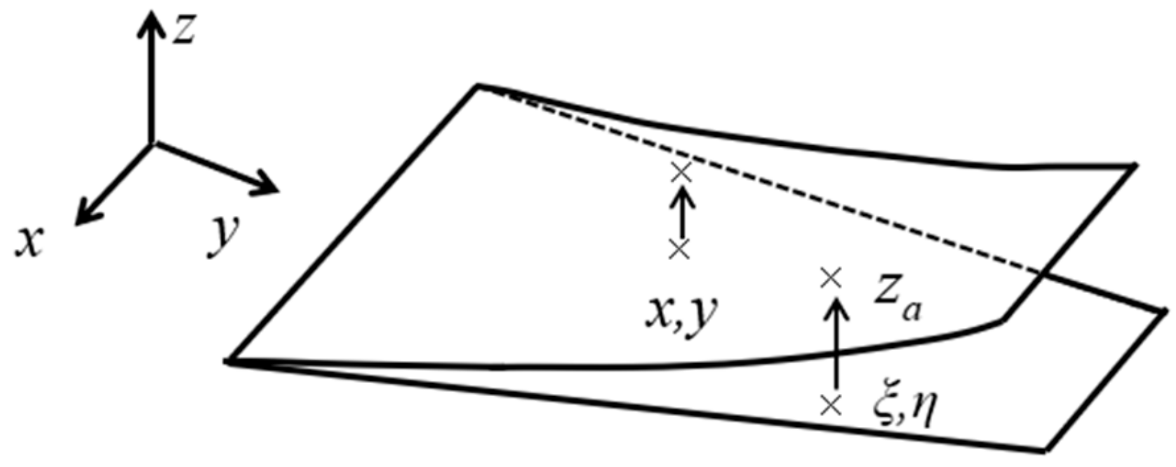
Figure 1. Deformation diagram of wing structure.
Fluids 05 00034 g001
Figure 2. Definition of coordinates in the Euler method.
Fluids 05 00034 g002
Figure 3. Schematic diagram of lifting surface grid in the doublet lattice method (DLM).
Fluids 05 00034 g003
Figure 4. FEM of body freedom flutter (BFF) wind tunnel test on the unmanned aerial vehicle (UAV).
Fluids 05 00034 g004
Figure 5. First three elastic modal shapes of BFF wind tunnel test UAV.
Fluids 05 00034 g005
Figure 6. Aerodynamic lifting surface model of BFF wind tunnel test UAV.
Fluids 05 00034 g006
Figure 7. Initially flutter characteristics of BFF wind tunnel test on the UAV.
Fluids 05 00034 g007
Figure 8. CAD model of the BFF wind tunnel test on the UAV.
Fluids 05 00034 g008
Figure 9. Process of wing and beam bonding.
Fluids 05 00034 g009
Figure 10. Completed UAV assembly and airborne equipment.
Fluids 05 00034 g010
Figure 11. Arrangement of a ground vibration test.
Fluids 05 00034 g011
Figure 12. The first three elastic modal shapes obtained from GVT.
Fluids 05 00034 g012
Figure 13. Revised flutter characteristics of BFF wind tunnel test UAV.
Fluids 05 00034 g013
Figure 14. Suspension system for the BFF UAV wind tunnel test.
Fluids 05 00034 g014
Figure 15. Wind tunnel test arrangement.
Fluids 05 00034 g015
Figure 16. Time-domain acceleration signal and frequency spectrum of wind tunnel test.
Fluids 05 00034 g016
Figure 17. BFF phenomenon observed during wind tunnel test.
Fluids 05 00034 g017
Figure 18. Time-domain acceleration signal and frequency spectrum at different conditions.
Fluids 05 00034 g018
Table 1. Detailed parameters of BFF wind tunnel test on the UAV.
ItemsValue
Total weigth (kg)2.072
C.G. (from nose, mm)385
Wing span (mm)2000
Aspect ratio10
Taper ratio1
Swept-back (degree)22.0
Table 2. First three elastic modal frequencies of BFF wind tunnel test on the UAV.
ModesFrequency (Hz)
Symmetric 1st bending3.40
Antisymmetric 1st bending10.70
Symmetric 2nd bending16.67
Table 3. The first three elastic modal frequencies obtained from GVT.
ModesFrequency (Hz)
Symmetric 1st bending2.90
Antisymmetric 1st bending8.98
Symmetric 2nd bending12.89
Table 4. Comparison of revised theoretical analysis result and GVT result.
ModesFrequency (Hz)Error (%)
TestedUpdated
Symmetric 1st bending2.902.87−1.03
Antisymmetric 1st bending8.988.85−1.44
Symmetric 2nd bending12.8913.796.07
Table 5. Comparison of wind tunnel test results and theoretical analysis.
BFF CharacteristicAnalyzedTestedError (%)
Flutter speed (m/s)9.499.722.37
Flutter frequency (Hz)2.032.186.88
Table 6. Effect of additional weight at nose increasing on the BFF characteristics.
Additional Weight (kg)Flutter Speed (m/s)Flutter Frequency (Hz)
AnalyzedTestedError (%)AnalyzedTestedError (%)
09.499.72−2.372.032.18−6.88
0.0669.6910.14−4.442.002.09−4.31
0.1469.9610.28−3.111.951.864.84
0.22110.2310.56−3.131.921.806.67