Abstract
One of the promising methods for process intensification for micromixing, co-precipitation, and crystallization in continuous reactors is the use of vigorous vortices. A combination of the high intensity of the kinetic energy input with the small volume of the micromixing volume allows to concentrate the energy dissipation rate up to 104 W/kg and more. As the embodiment of such an idea, four new types of microreactors with intensively swirled flows were created and studied as a tool for continuous co-precipitation and crystallization. A correlation between residence time and segregation index was found: the smaller residence time, the higher energy dissipation rate and better quality of micromixing. A method for the synthesis of oxides of a number of transition metals in microreactors with intensively swirled flows with subsequent thermal treatment of co-precipitation products has been developed. This method was used to obtain ensembles of nanosized particles of zirconium oxides, as well as calcium and strontium fluorides. In comparison with the currently widely used hydro- and solvothermal methods, the proposed method has high productivity (around 10 m3/day for lab scale device), can significantly reduce the duration of the process, provides low energy consumption, does not require a large number of labor-intensive operations, is technologically advanced and easily scalable.
1. Introduction
1.1. Macroscaled Reactors vs. Milli or Microscaled Reactors
Some general principles of nanosized particle formation by the use of microreactors with impinging jets are discussed in our paper [1]. Though there are some general ideas applicable to any type of microreactor [2,3,4,5], the microreactors with swirled flows have some peculiarities described in the present paper.
In the work [6] two possible ways of nucleation are discussed—homogeneous and heterogeneous (aggregative) nucleation. Here we consider the latter one as the main route of nucleation.
In connection with these concepts, as well as the needs of industrial plants for the production of nanosized particles in the solution synthesis of oxide and other inorganic compounds, an idea arises in the formation of controlled hydrodynamic, thermodynamic and physicochemical conditions that make it possible to obtain nanosized particles with predictable sizes, structure and chemical composition and shape.
It should be especially noted that it is precisely the combination of the most favorable hydrodynamic conditions that ensure the mass transfer at the macroscale and then at the microscale level, along with thermodynamic and physicochemical conditions, that can provide the solution to the most complex problems of nucleation and particle growth controlling.
The hydrodynamic conditions, moreover, make it possible to control heat exchange processes that play a key role, for example, during hydrothermal (solvothermal) treatment, as well as during drying and heat treatment of nanoparticle powders.
In particular, it seems promising to create such conditions for the flow structuring:
- (1)
- At the first stage of the process, the substances participating in the formation of particles are distributed fairly uniformly over the volume of the solution at the lowest possible size level, i.e., at the ionic level. As a result of such uniform distribution, the formation of clusters (with a size less than the critical size of the nucleus) with a given chemical composition is ensured.
- (2)
- After the first stage, there is a short period of time (the second stage) during which the formation of nuclei from clusters occurs. The second stage is needed to allow the clusters to aggregate into nuclei.
- (3)
- At the third stage of the process, after the formation of clusters and nuclei, the separation of particles is necessary, which prevents their further spontaneous uncontrolled growth.
The “art” of process control here consists of the following positions:
- (a)
- To give an opportunity to form nuclei (either amorphous or crystal) with a given chemical composition and structure.
- (b)
- To allow them to reach a critical size (or slightly larger, depending on the main task of synthesis).
- (c)
- To separate particles in space after the formation of nuclei, as far as possible preventing them from forming larger aggregates and agglomerates.
This approach is described in more detail in [1]. It should be noted that in the work [1] the general ideas of the micro/milli scale approach are discussed, with applications to the microreactor with free impinging jets. In the present paper, some of these ideas are extended and their applications to the microreactors with swirled flows and impinging swirled flows are demonstrated.
From a practical point of view, the most convenient tool for the “design” of nanosized particles would be a hypothetical device that allows one to select the desired atoms and place them in the lattice of the crystals being grown in a proper way. Although certain attempts in this direction (hereinafter we will call it the “nano-approach”) could be done, e.g., based on the use of powerful electromagnetic fields (which were applied for instance for catalytic reactions [2,3,6,7]) and it is possible to imagine the use of nanorobots (which are quite widely studied for biomedical application [4,5,8,9]). The advantage of this approach appears to be the guaranteed selectivity, but the performance of this approach for the synthesis of nanosized particles is still a challenge due to some technical limitations.
Such a correct transition from the milli- or microscale to the nanoscale is capable of providing, on the one hand, a sufficient quality of the resulting nanoparticles, and on the other, acceptably high productivity.
At the same time, traditional macroscale approaches based on the use of various kinds of mixing and ultrasonic devices, autoclaves, etc. in the processes of “wet” chemistry, allow a rather significant increase in productivity compared to the nano-approach, but the question of the quality of the resulting product, including the well-known triad “composition-structure-properties” (Figure 1) remains open.
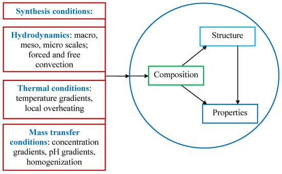
Figure 1.
Block diagram of the effect of synthesis conditions on the composition, structure, and properties of nanoscale materials.
In this regard, it seems promising to use intermediate spatial and time levels of external effects on solutions, namely at micro- and milliscale, i.e., within a range of 10−5 m to 10−2 m for space scale (area of micromixing) and in the range of 10−5 s to 10−3 s for time scale (duration of mixing). For comparison, it should be noted that usual macroscaled reactors provide a space scale in the range of 10−1 m to 100 m and a time scale in the range of 103 s to 105 s. In the case of micro and milliscaled reactors, the synthesis conditions-hydrodynamic, thermal, and mass transfer (see Figure 1) should be adequate to the requirements for the composition, structure, and properties of the resulting nanosized particles.
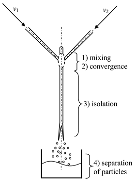
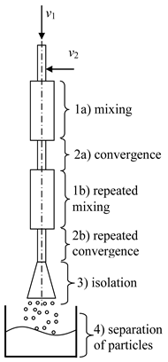
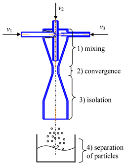
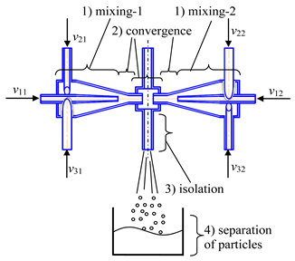
Some examples of the implementation of processes for the synthesis of nanosized particles in microreactors of various types are demonstrated in Table 1.

Table 1.
Examples of the implementation of processes for the synthesis of nanosized particles in microreactors of various types.
In Figure 2, the space and time levels of the formation of nanosized particles—from the atomic and ionic level through the nanosized particles, milli and microscale to the macro level are shown. Obviously, the traditional route from the large-sized macro-level devices to the nanosized particles is much longer than the way from milli and microscaled reactors, and accompanied by the formation of unnecessary by-products [1]. Hence, the milli and microreactors appear to be promising tools for the formation of nanosized particles.
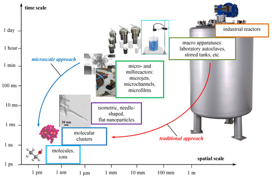
Figure 2.
Spatial and temporal levels of formation of nanosized particle.
1.2. Macro-, Meso- and Micromixing Scales
According to the classical point of view, large-scale eddies, as a result of the excess of inertia forces over the viscous forces, break up into medium-scale eddies, then into smaller and smaller ones until the minimum scale of turbulence according to A.N. Kolmogorov is achieved [13].
In a recent work [13] an influence diagram of turbulent vortices at all space-time levels on mixing processes is shown. More details of the mixing process were also discussed in [14,15,16,17]. Three levels of mixing are distinguished:
- Macro-mixing corresponds to the whole scale of the apparatus (i.e., it has a spatial order of the apparatus diameter, the stirrer diameter). It determines the conditions for the transfer of matter by large-scale convection over the entire volume of the flow in the reactor and is characterized by the average velocity of macrovolumes movement and the residence time distribution. Essentially, the average residence time characterizes the duration of the liquid macrovolumes “live”, from the input into the apparatus to the output from it. This movement is responsible for the transfer of liquid macrovolumes from the “passive” zones to the zones with a high energy dissipation rate (in the immediate vicinity of the mixer). A simple example is the circulating flow in a reactor with a pitched blade or Rushton turbine.
- Meso-mixing takes place at an intermediate level and is responsible for large-scale turbulent transfer between the energy-carrying flow introduced into the apparatus (stirrer, free-convective flows, jets, bubbling gas, etc.) and its environment. A fast chemical reaction usually takes place near the point of entry (zone of “feed”, entry of the “fresh” stream), which forms a “plume” (blob) with a high concentration of product around the injected stream. This plume is an intermediate scale between the micromixing level and the size of the reactor. The spatial evolution of the plume is determined by the turbulent diffusion process. Another aspect of meso-mixing relates to the inertial-convective process of disintegration of large vortices and is characterized by an almost complete absence of the influence of molecular diffusion since the dominant mechanism is convection. On the other hand, inertial-convective mixing influences micro-mixing processes. A complete understanding and precise description of inertial-convective mixing are still lacking. The turbulence kinetic energy k, the scale of the length of turbulent fluctuations L, and their combination, expressed by the coefficient of turbulent diffusion Dt, are used as quantitative characteristics of meso-mixing. At the same time, meso-mixing also depends on specific conditions, such as the geometry of the apparatus, the ratio of the feed rates, and the average flow velocity in the apparatus.
- Micro-mixing is the last stage of mixing in traditional apparatus and consists of viscous-convective deformation of liquid elements, which accelerates the disintegration of liquid aggregates up to the diffusion scale [18]. The selectivity of the reactions ultimately depends on micromixing, i.e., on how the reagents are mixed at the molecular level [16]. This mechanism entails the engulfment and deformation of vortices of the Kolmogorov scale λk and is the limiting process in reducing local concentration gradients. Quantitative characteristics are the micro-mixing time associated with the energy dissipation rate ε [16]: the higher ε, the better the micromixing and the higher the selectivity of fast reactions.
The evolution of the liquid elements in the form of microvortices and the engulfment is presented in Figure 3: the simultaneous stretching and elongation of the vortices result in the engulfment of the surrounding liquid. As a result, thinner layers of liquid are formed, and the thickness of the layer δ (see Figure 3) is responsible for the diffusion characteristic time: tdif ≈ δ2/D. Therefore, with thinner layers in microvortices much better micromixing is expected.
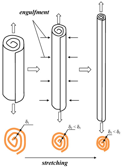
Figure 3.
Elongation, stretching of microvortices, engulfment of surrounding bulk liquid.
Hence, the thinner layers (δ2, δ3) create better conditions for the collision of the ions (for homogeneous nucleation) and the sub-nanosized pre-nuclei (for aggregative nucleation). Therefore, the formation of intensely swirled flow is expected to be a tool for the formation of extremely small microvortices with high vorticity ω (ω ∝ ∂wt/∂r), especially in the neck volume, as shown in Figure 4. See the detailed discussion on the velocity increase in the neck volume in Section 2.3 of this paper.
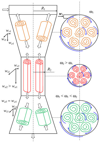
Figure 4.
Variation of the axial, tangential, and radial velocity projections and vorticity along the axis of the microreactor with swirling flows. R—radius, m; wa, wt, wr—axial, tangential and radial components of liquid velocity, m/s; w—velocity vector, m/s; ω—vorticity, 1/s; 1, 2, 3—indexes referred to different parts of the microreactor.
In other words, the use of swirled flows, especially at the micro (or milli) level expected to provide better micromixing; hence, the formation of the nanosized particles with better characteristics (smaller mean size of aggregates, purity of the final composition due to excellent micromixing, ability to control the process and high performance of the microreactors/micromixers with swirled flows) is expected.
The aim of this paper is to demonstrate the advantages of microreactors with swirled flows, to compare the operation mode of four types of such microreactors, and to represent some successful results of nanosized particles formation synthesized in microreactors with swirled flows.
A method for the synthesis of oxides of metals in microreactors with intensively swirled flows (having various geometry) with subsequent thermal treatment of co-precipitation products has been developed. This method was used to obtain ensembles of nanosized particles of zirconium oxides, as well as calcium and strontium fluorides. In comparison with the currently widely used hydro- and solvothermal methods, the proposed method has high productivity (around 10 m3/day for lab scale device) can significantly reduce the duration of the process, provides low energy consumption, does not require a large number of labor-intensive operations, is technologically advanced and easily scalable. It should be pointed out that the proposed method of synthesis is in fact an enhanced sol-gel process.
The significance of this work is to demonstrate the advantages of microreactors, particularly microreactors with intensively swirled flows for the almost instant synthesis of nanosized particles of inorganic materials. It will be demonstrated that the fast and intensive micromixing allows for avoiding the formation of impurities and hindering the growth of aggregates during this enhanced sol-gel method. Not the last preference for industrial applications is an easy scale-up because the proposed method provides high productivity (up to 10 m3/day of suspension, i.e., 200–300 kg/day of particles).
2. Features of Hydrodynamics of Microreactors with Swirled Flows of Different Types
In this section, the operation principles and advantages of various microreactors with swirled flows are described.
2.1. Descriptions of Four Microreactors with Swirled Flows
- (1)
- Microreactor with swirled flows (Table 1, c) contains a housing, two or more feeding pipes for supplying initial solutions, and an outlet pipe for removing products, the housing has the shape of a cylinder with a lid, which turns into a conical confuser with a neck in a narrow part and subsequent conical expansion in the form of a diffuser.
One of the feeding pipes is installed in the lid coaxially with the housing, and the end of this pipe is made in the form of a nozzle, the tip of which is located in the throat area, and the remaining feeding pipes are installed tangentially on the cylindrical part of the housing.
The initial solutions are pumped from flasks with predetermined flow rates into the feeding pipes. The total flow rate of the supplied solutions should be sufficient to ensure a high swirling rate of the flow in the throat zone (circumferential speed of the order of wt2 ≈ 15–25 m/s, from our experience).
An inert gas could be supplied to the central feeding pipe at a flow rate that ensures the formation of gas bubbles in the neck volume. Optionally, instead of gas, a solution of one of the reagents can be supplied to the central feeding pipe.
When the solutions are fed into the tangential pipes, the flow swirls, approaching the throat at different or the same velocities (depending on initial flow rates), so that a powerful shear field arises in the throat zone leading to a high level of micromixing, and the pressure can become lower than atmospheric, which leads to the appearance of cavitation bubbles in the solutions.
The gas supplied through the central pipe disintegrates into small bubbles under the action of the shear field at the outlet of the nozzle. Thus, the bubbles can form either as a result of cavitation (if there is a sufficient vacuum in the throat) or as a result of the dispersion of an inert gas supplied to the nozzle through the central pipe to the throat.
In the throat zone, extremely intensive mixing of all supplied components occurs, firstly, due to the high level of axial and tangential velocities in this zone (resulting in elongation of microvortices), secondly, due to the powerful shear field induced by high velocities, and thirdly, due to micropulsations of the bubbles surface, as an additional intensification of mixing.
- (2)
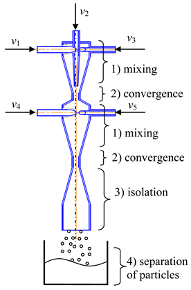
- Two-step (multistage) microreactor with swirled flows (two-step/multistage micro-VJA) (Table 1, e). A multistage (particularly, two-step) swirling flow microreactor contains a body, pipes for supplying solutions of the reacting components, and a pipe for product removal. The body has a multitier shape, each tier corresponds to one mixing stage, the tiers are located coaxially to each other, each tier includes a lid, a cylindrical part that turns into a conical confuser with a neck in a narrow part, and the last tier is equipped with a conical expansion in the form of a diffuser, with an outlet for the removal of the product. At least one feeding pipe is installed on each tier tangentially to the cylindrical part of the body, and a central feeding pipe is installed in the cover of the upper tier coaxially with the body.
The device operates in the following way. The solutions are supplied by pumps from the flasks with specified flow rates into the feeding pipes. The total flow rate of the supplied solutions should be sufficient to ensure a high swirling speed of the flow in the throat area (peripheral in the feeding pipes of the order of wt1 ≈ 3–5 m/s, the peripheral speed in the throat is of the order of wt2 ≈ 15–25 m/s, from our experience). The diameters of the throats in different tiers can be made with different diameters (with an increase in the direction of the flow), taking into account the increase in the total flow rate of the supplied flows, increasing from the first tier to the next. For the same reason, the diameters of the cylindrical part in different tiers can be made with an increase in the direction of the flow.
Into the central pipe are fed the solutions of reacting components, for example, solutions of doping elements, an inert gas, a homogeneous catalyst, or a suspension with catalyst particles, etc. The role of the inert gas (supplied with a flow rate of about 0.1–0.5% of the total solution flow rate) is to further intensify the micro-mixing processes due to oscillations of the bubble surface, which leads to a redistribution of the turbulent energy of pulsations and an improvement in mass transfer processes near the liquid-gas phase boundary.
Like in the previous case the bubbles can be formed either as a result of cavitation (if there is a sufficient vacuum in the throat) or as a result of the dispersion of an inert gas supplied to the nozzle through the central pipe.
Again, like in the previously described microreactor, there are three mechanisms of micromixing intensification: the high level of axial and tangential velocities (with corresponding shear and tensile stresses), powerful shear field, and micropulsations of the surface of the bubbles.
As a result, in the area of the neck of the first tier, the first stage of the mass transfer process (including those with conjugated chemical reactions) takes place. The intermediate product from the first stage enters the second tier, where solutions of the components participating in the second stage are introduced through the tangential pipes.
For example, in the first tier, a core of nanosized particles is formed, and in the second tier, its shell will form. In the second tier, intensive mixing also occurs, due to both the residual swirling of the liquid flow entering from the throat of the first tier into the second tier, and the additional swirling of the flows supplied through the tangential pipes belonging to the second tier. In the area of the neck of the second tier, the second stage of the mass transfer process is completed (including coupled chemical reactions). The final product in the form of suspension moves then to the diffuser and is discharged through the outlet.
- (3)
- Microreactor with impinging swirled flows (counter-current axial velocities) (micro-VJA-ISF-CC) (Table 1, d) contains housing, nozzles for supplying solutions of initial components, feeding pipes for supplying solutions of additional components. The body of a microreactor consists of two swirl chambers, each of which is similar to the case shown in Table 1, c. The throats of each swirl chamber are located coaxially to each other in a mixing chamber equipped with an outlet pipe for products, and there is an axial gap between the throats.
The device operates in the following way. The initial solutions are supplied by pumps from flasks with predetermined flow rates into the feeding pipes. The total flow rate of the supplied solutions should be sufficient to ensure a high swirling speed of the flow in the area of the necks (the peripheral speed in nozzles of the order of wt1 ≈ 3–5 m/s, the peripheral speed in the throat is about wt2 ≈ 15–25 m/s, from our experience).
Like in the previous cases, additional components are fed into the central pipes (for example, solutions of doping elements, an inert gas, a homogeneous catalyst, or a suspension with catalyst particles, etc.). The role of the inert gas is to further intensify the micromixing processes due to oscillations of the bubble surface, which leads to a redistribution of the turbulent energy of pulsations and an improvement in mass transfer processes near the liquid-gas interface.
The main operations of this device are similar to those for the microreactor with swirled flows. The main difference consists of the additional chamber with a gap between the throats, where two countercurrent swirling flows impinge. Due to the summation of their impulses and kinetic energies, the effect of micromixing is higher for this device than for the two previous ones.
- (4)
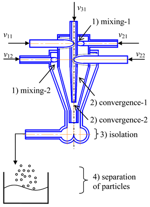
- Microreactor with impinging swirled flows (co-directional axial velocities) (micro-VJA-ISF-CD) (Table 1, f) contains a housing, feeding pipes for supplying initial solutions and additional components, and an outlet pipe. The housing of the microreactor is made of two coaxially arranged swirl chambers, each of which contains a cover, a cylindrical part, passing into a conical confuser with a throat in a narrow part.
In each swirl chamber, tangentially to the cylindrical part of the body, one or more feeding pipes are installed in such a way as to ensure the swirling flows in the swirl chambers in the opposite direction. One of the swirl chambers is located inside the other with the formation of an annular gap between them along the entire length, and in the cover of the inner swirl chamber coaxially with the body there is a feeding pipe for additional components, and the neck of the outer swirl chamber is made elongated to form a mixing chamber with subsequent expansion of the flow, equipped with an outlet pipe for the removal of the product.
Note here the term “co-flowing” relates to the flow before the solutions meet in a mixing chamber. In the mixing chamber, two swirling flows impinge, like in the previously described device.
The device operates in the following way. The initial solutions are pumped from flasks at predetermined flow rates into the feeding pipes. The total flow rate of the supplied solutions should be sufficient to ensure a high swirling speed of the flow in the throat (the circumferential speed in the pipes is about wt1 ≈ 3–5 m/s, the circumferential speed in the throat is about wt2 ≈ 15–25 m/s, from our experience). Additional components are fed to the central pipe, for example, solutions of doping elements, an inert gas, etc. The role of the inert gas is to further intensify the micro-mixing processes due to oscillations of the bubble surface, which leads to a redistribution of the turbulent energy of pulsations and an improvement in mass transfer processes near the liquid-gas interface.
In general, this device operates very similarly to the microreactor described in the previous section. The only difference is the axial directions of the supplied flows: for the microreactor with impinging (counter) swirled flows the axial velocity vectors wa1, wa2 are countercurrent, whereas for microreactor with co-flowing impinging swirled flows these velocities are co-directional.
2.2. Comparison with the Microstructured Cyclone Type Micromixer (KIT)
It should be noted that the micromixers described in Section 3.1 differ significantly from the microstructured cyclone type micromixer (MCTM) [19,20], though there are some similar (centrifugal and other) effects.
The MCTM contains a cylinder with 0.5- or 1.0-mm inner diameter and two tangential feeding pipes. The length of the cylinder was varied in the range of 1 to 5 mm (see [20] for details). It was shown in [20] that MCTM demonstrates very good mixing characteristics. The similarity of the microreactors with swirled flows presented in this paper is the tangential input of the solutions and swirling flow. The differences are:
- (1)
- In new microreactors the flow has a varying cross-section. The confinement in the confuser results in the acceleration of both vorticity ω and circular velocity wt in the area close to the throat of the device. This leads to the additional elongation and stretching of the vortices (see Figure 3); hence, better engulfment and micromixing could be expected.
- (2)
- In new microreactors with impinging swirled flows the impingement of the results of the flow in the transformation of doubled kinetic energies during flow collision. This is expected to bring an additional increase in micromixing.
2.3. Velocity Transformations within Microreactor with Swirled Flows
The flow, entering the confuser through the tangential branch pipe (Figure 4) with the initial velocity w1, swirls, with the tangential component of velocity is wt1. Moving from the cylindrical zone with the radius R1 to the neck area of the confuser with the radius R2, the flow is accelerated. In the case of an ideal fluid (i.e., with zero viscosity) in accordance with the angular momentum conservation law:
where m is a mass of an elementary volume of liquid, and the tangential component of the velocity at the entrance of the throat is
i.e., .
By integrating the Bernoulli equation for an ideal fluid flow in a vortex tube (two-dimensional problem), a dependence of pressure on the radius r was obtained
where p1 is the pressure of the flow at the radius R1; ρ is a liquid density.
From Equation (2) it follows that with decreasing radius r, the pressure decreases, and, for example, at the entrance to the throat (r = R2), the pressure near its walls will be
from what follows that p2 < p1, i.e., the pressure at the entrance to the throat (at radius R2) is significantly lower (and on the axis of the throat, i.e., at the center of the vortex the pressure is even lower) than in the cylindrical part of the confuser (at radius R1).
Thus, the tip of the central pipe (the nozzle) is in the zone of reduced pressure, which contributes to the suction of the injected medium through the central pipe into the throat of the apparatus. Hence, the microreactor with swirling flows provides for the effective transformation of the kinetic energy of the rotational motion: (i) into an increased vacuum in the throat, (ii) into the flow with increased velocity and, due to the smaller size, with higher shear stresses.
In the confuser near the entrance to the throat, there is a reduced pressure p2 (p2 < p1). Under the action of the arising pressure drop Δp = p1 − p2, the injected flow begins to be sucked into the confuser 1 through the tangential branch pipe, which, while swirling, acquires the tangential (circumferential) velocity component: in the cylindrical part of the confuser wt1, at the entrance to the throat wt2, and these velocities are related to each other by relation (1). The link between velocities and the arising pressure difference can be expressed in the first approximation (for ideal liquids) from Equation (3) in the form:
In addition to the tangential component, for three-dimensional problems the axial wa and radial wr components of the velocity undergo changes, and Equation (3) should therefore contain the full kinetic energy of the flow. If we take into account the relation for the total velocity known from the kinematics of the fluid
then instead of Equation (3), the integral of the Bernoulli equation should be written in the form
where w1 is the total velocity of the flow at the radius R1.
Considering that the confuser angle is small, we can assume that . In addition, due to the dependence wa ∝ R–2 (which follows from the continuity equation) at R1 > >R2, the relation wa2 >> wa1 is valid. Then, instead of Equation (4), a more accurate expression for the ideal liquid could be written
In the case of studied microreactors due to the presence of the lid near the input nozzle, the axial component wa1 ≈ 0. From Equation (7) it follows that the pressure drop created by the flow is spent on changing the kinetic energy of the injected flow, and in addition to changing the tangential motion (velocity component wt2), the injected flow also acquires an axial one (velocity component wa2).
Note that the additional (tangential) velocity component presented in Equation (7) also plays important role in the kinetic energy of the flow, as follows from Equation (5). The increase of the tangential velocity wt2 in the throat area along with increased axial velocity results wa2 leads to the growth of the total velocity vector and therefore, the kinetic energy K = ρw2/2 in the throat area grows as well.
As mentioned before, the energy dissipation rate is a key input parameter characterizing the micromixing intensity (see also Equations (10)–(12) in Section 2.4).
Hence, the energy dissipation rate ε in microreactors with swirled flows is expected to be higher compared to similar reactors, including microstructured cyclone-type mixers (MCTM). It should be noted that the energy dissipation rate depends both on the dissipated energy and the volume
The volume of the micromixing zone for the two-step microreactor with swirled flows was measured experimentally and the correlation between residence time and a segregation index was found, see Section 2.4.
2.4. Experimental Study of Micromixing in Two-Step (Multistage) Microreactor with Swirled Flows
An experimental study of micromixing in a two-step microreactor with swirled flows was performed by means of the iodide-iodate method [21,22]
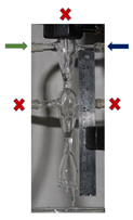
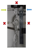
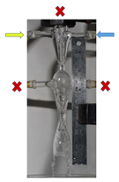
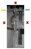
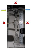
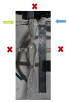
Table 2 demonstrates photographs of the steady-state flow in the apparatus. Both solutions were supplied through the tangential pipes. The total volume of the upper chamber is Vup = 3.75 mL, and the lower chamber Vlow = 3.85 mL.

Table 2.
Photographs of flow in the two-step microreactor with swirled flows and estimated volume of the micromixing zone Vμm for various flow rates Q1 and Q2.
The volume of the micromixing zone Vμm in the upper chamber was defined as follows:
Vμm = φ Vup
Residence time in the upper chamber was calculated by equation
From Figure 5 it follows that the smallest residence time (about 40 ms) is high enough to let the chemical reaction definitely occur during this time (the time of the particle formation is estimated at about 1 ms). On the other hand, for the iodide-iodate method the increase of residence time obviously leads to competition between reactions; therefore with increasing tres the segregation index Xs grows as well (see Figure 5).
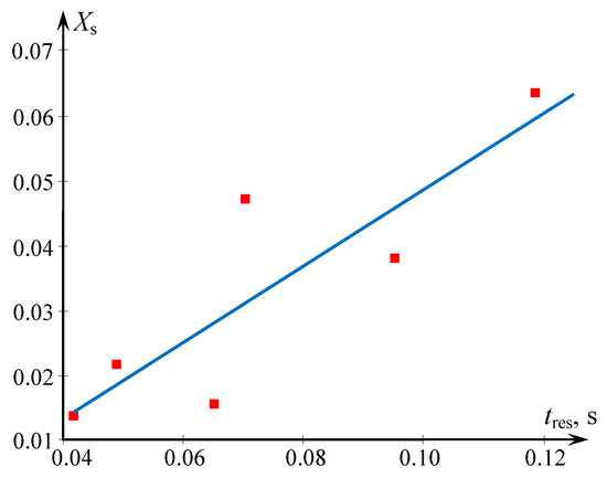
Figure 5.
Dependence of the segregation index Xs on the residence time in the two-step microreactor with swirled flows. Solutions were supplied to the tangential pipes (see Table 2). Points—our experimental data, blue line-linear correlation (Xs = 0.589 tres − 0.01).
Besides, one of the findings of [22] is the equation linking the micromixing time tm for several types of studied microreactors with the energy dissipation rate ε:
From the analysis of the energy dissipation rate definition, it was found in [22] that for laminar flow the mixing time for laminar flow is related to the energy dissipation rate as
Note that Equation (10) qualitatively coincides with Equation (11). Similarly to Equation (11), for turbulent flow following relation could be found:
Obviously, the higher the energy dissipation rate, the smaller the mixing time, as follows for Equation (12) (note that for studied microreactors in a majority of cases flow regime was turbulent). Hence, the smaller values of tres in Figure 5 correspond to the higher energy dissipation rate ε, and the higher ε, the smaller Xs (better quality of micromixing).
3. Examples of the Nanosized Particles Synthesis in Microreactors with Swirled Flows and Microreactors with Impinging Swirled Flows
3.1. Synthesis of Zirconium Dioxide Based Powders in a Microreactor with Impinging Swirling Flows
A microreactor with impinging swirled flows (with counter-current axial velocities) (micro-VJA-ISF-CC) was used in this study.
In the work [23] the comparative synthesis of mesoporous nanosized xerogels of ZrO2–Y2O3 (97% mol. ZrO2—3% mol. Y2O3) and particles by use of (i) co-precipitation of hydroxides and (ii) microreactor with impinging swirled flows (micro-VJA-ISF-CC) was performed. This material is used for dental prostheses.
Diluted (~0.1 M) aqueous solutions of analytical grade zirconium oxynitrate (ZrO(NO3)2·2H2O) and analytical grade yttrium nitrate (Y(NO3)3·6H2O) were chosen as the initial components. An aqueous solution (~1 M) of pure-grade ammonia NH4OH was used as an antisolvent.
To decrease the intensity of the particle agglomeration the precipitates have been frozen at –25 °C (within 24 h). The drying of the precipitates was performed in the air in a muffle furnace PMF-8/RT-900 at 110 °C in corundum bowls within 2 h. The annealing of the xerogeles was performed in a furnace SNOL 6.7/1300 at 600 °C in the air in corundum bowls within 1 h.
The details of the analysis of the powder are presented in [23].
Acid-base characteristics of xerogeles were examined by use of a pH meter. It was found that the sample obtained by the coprecipitation method is characterized by a sharp decrease in the pH of the aqueous suspension during the first 10 s after immersion of the sample, which indicates the predominance of Lewis acid sites (LASs) on their surface, which are capable of rapid interaction with water with the elimination of OH-groups from it.
For the sample obtained using Microreactor with impinging swirled flows, a smooth decrease in the pH of the suspension is observed. Such behavior demonstrates the predominance of Brønsted acid sites (BASs) on the surface of xerogel particles, which may be associated with disordering element-oxygen bridge structure and surface hydroxylation. Particles with BAS contain surface OH groups with higher oxygen-hydrogen bond energy with an element-oxygen bond and a tendency to hydroxyl elimination.
The surface of the particle formed during the synthesis has excess energy, which contributes to the saturation of bonds due to the adsorption of molecules from the environment. When the precipitate is in the mother liquor, the processes of coalescence and flocculation begin to occur, under the influence of which aggregates of highly dispersed particles are formed [24]. If water is adsorbed on the surface of particles coated with hydroxyl groups or cations, relatively unstable molecular complexes may form. Their further aggregation due to the occurrence of the condensation reaction leads to the formation of rigid agglomerates, in which the particles are connected to each other by the forces of chemical bonding [25]. Thus, xerogels obtained using the microreactor with impinging swirled flows (micro-VJA-ISF-CC) have a lower level of agglomeration compared to xerogels obtained by coprecipitation. It was found in [23] that xerogel obtained in micro-VJA-ISF-CC features a reduced agglomeration of the particles that correlates with their lower surface acidity compared with the co-precipitated xerogel, reflecting a decreased content of active surface centers.
It was also found that the zeta potential of the particles is 24.21 ± 1.44 mV (for coprecipitation) and 11.89 ± 1.90 mV (for micro-VJA-ISF-CC), which confirms the presence of acid sites on the surface of xerogel particles. It is worth noting the hydrodynamic diameter of the particles of the coprecipitated xerogel is much larger than the size of the xerogel particles obtained using micro-VJA-ISF-CC, which is also confirmed by scanning electron microscopy.
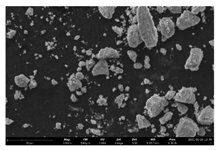
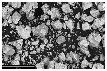
The xerogel obtained by the coprecipitation method consists mainly of irregular agglomerates with sizes from 0.1 to 120 μm (Table 3, line 3). A xerogel obtained using micro-VJA-ISF-CC consists of smaller agglomerates with clear boundaries ranging in size from 0.1 to 75 μm [26].

Table 3.
Summary of synthesis results in various types of Microreactors with impinging swirled flows (micro-VJA-ISF-CC).
The pore size distribution found by means of nitrogen absorption was found to be within the range of 2 to 9 nm for coprecipitation with inkpot-like mesopores, and in the range of 2 to 5 nm for a micro-VJA-ISF-CC method with a predominance of the slit-like mesopores. Hence, in the latter case, the size of the pores is smaller.
3.2. Synthesis of Fluorides in Microreactor with Impinging Swirled Flows
For the synthesis of calcium fluoride, the following reagents were used: calcium nitrate tetrahydrate (pure grade), potassium fluoride dihydrate (pure grade), and distilled water. The concentrations of the initial solutions are [KF] = 0.7692 M and [Ca(NO3)2] = 0.3846 M. A series of experiments was carried out in micro-VJA-ISF-CC with a set of reagent flow rates (2.1 L/min, 2.6 L/min, and 3.2 L/min), the “head” and “tail” of the solutions were poured into a separate container to assure the steady state process conditions. The synthesis was carried out at room temperature. More synthesis details are described in the work [27], see also Table 3, line 1. CaF2 (fluorite) is used in metallurgy as well as a low-dispersion optical material for a wide spectrum (from UV to IR waves).
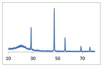
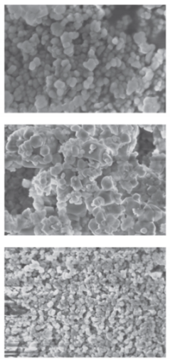
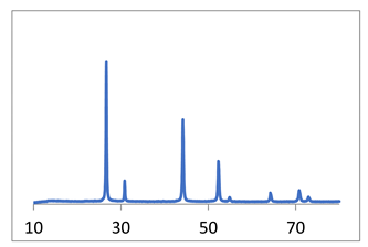
X-ray diffraction diagrams of the powder and SEM micrographs are shown in Table 3, line 1.
SEM data (Table 3) indicate that an increase in the reagent feed rate leads to an increase in the homogeneity of the powder and a slight decrease in the particle size. The narrowest particle size distribution is observed in the micrograph of the CaF2, sample 3 (Table 3); particle sizes are 40–80 nm. In the CaF2 sample 2 (Table 3), a bimodal distribution of particles is observed, the size of the “fine” fraction is from 60–120 nm, and the larger particles are about 400–600 nm. Comparing this picture with the calculation of coherent scattering regions, we can conclude that particles, especially large ones, are agglomerates. The particle sizes of the CaF2 sample 1, determined from the micrograph (Table 3), are 40–120 nm.
In the work [27], it is noted that the particles of fluorite obtained as a result of syntheses are devoid of faceting. This applies not only to large and medium agglomerates but also to nanoparticles, the sizes of which correspond to the calculated value of the coherent scattering regions ~40 nm (Table 3).
The absence of faceting at a low synthesis temperature is a sign of processes far from equilibrium, namely, an indicator of a non-classical mechanism of crystal growth by nanoparticle agglomeration [28].
Thus, the use of a microreactor made it possible to obtain calcium fluoride powders with an average size of coherent scattering regions of about 40 nm. An increase in the rate of consumption of reagents prevents the formation of agglomerates and improves the granulometric uniformity of the powder. Table 3 summarizes the results of synthesis in various types of microreactors with swirled flows. Examples of the synthesis of calcium fluoride, strontium fluoride, and zirconium oxide in a reactor with swirling flows are given. Synthesis details are given in the corresponding papers (right column).
4. Conclusions
The use of the level closer to the nanoscale, namely milli and microscale appears to be a more appropriate tool for the formation of nanosized particles, compared to the common macroscale devices used for the co-precipitation method.
The microscaled swirled flows generated in the microreactors, allow to increase in the quality of micromixing in small volumes of mixed solutions of precursors and antisolvent within a very short time, comparable with the formation of the nanosized clusters. As a result, the agglomeration rate decreases in the microreactors with swirled flows.
Four types of recently developed microreactors with swirled flows are described in the paper, including the principles of their operation and some advantages. To the latter belong the acceleration in the volume of the neck, and the decrease of the linear sizes in the neck (due to the conical confuser) where the main amount of the kinetic energy of the flow is dissipated. This results in a higher density of energy dissipation in the neck volume, and better micromixing; thus, better conditions for the formation of nanosized particles are created. Besides, further expansion of flow allows to separate just formed particles and avoid their rapid agglomeration.
In new microreactors with swirled flows, the flow has not constant cross-section. The confinement in the confuser results in the acceleration of both vorticity and circular velocity in the area close to the throat of the device. This leads to the additional elongation and stretching of the vortices. In new microreactors with impinging swirled flows the impingement of the results of the flow in the transformation of two kinetic energies during flow collision into the deformation of liquid and mixing (energy of deformation and further dissipation).
The new apparatuses were successfully tested on the synthesis of several systems (fluorides and complex oxides).
Using the YAG (yttrium aluminum garnet, Y3Al5O12) as an example, it has been shown that when using a microreactor with impinging jets (similar to Microreactors with impinging swirled flows by micromixing parameters), in comparison with standard methods of synthesis, YAG is formed at a lower temperature (1000 °C) of annealing [29]. The CSR (coherent-scattering region) sizes are 23–27 nm, which indicates the formation of nanosized YAG crystals in the microreactor. Under similar conditions, upon calcination, a mixture of hydroxides was obtained by the coprecipitation method, and a mixture of several phases was formed. To form the YAG phase, heating to 1200–1300 °C was required. Thus, the use of microreactors significantly simplifies the synthesis procedure and allows one to dramatically increase productivity, and reduce time and energy costs.
Calcium and strontium fluorides were obtained in micro-VJA-ISF-CC; the use of a microreactor made it possible to obtain calcium fluoride powders with an average size of coherent scattering regions of about 40 nm.
An increase in the flow rate of reagents prevents the formation of agglomerates and improves the granulometric uniformity of the powder. As in the case of YAG, in comparison with the standard coprecipitation method, micro-VJA-ISF-CC simplifies both the synthesis procedure and allows one to dramatically increase productivity, and reduce time and energy costs.
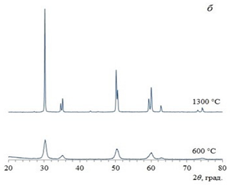
It was found for zirconium dioxide that xerogel particles obtained in a microreactor with counter-swirling flows are less susceptible to agglomeration. It is shown that, after heating of xerogels at 600 and 1300 °C, the powders obtained by two selected methods (co-precipitation and microreactor synthesis) also have comparable CSR (coherent-scattering region) sizes. At the same time, the new synthesis method studied in this work with the use of a microreactor with counter-swirling flows makes it possible to carry out a continuous synthesis process with high productivity with guaranteed parameters of the resulting product.
The Microreactors with swirled flows and Microreactors with impinging swirled flows allow them to mix rapidly and with very high-performance several flows (up to 10 in the elaborated devices). At the moment some studies are in progress that allow for the formation of particles having a more complex structure (e.g., the crystals with pyrochlore structure). It is worth noting even lab-scale micro-VJA are capable of producing about 10 m3/day of suspension with nanosized particles (at a flow rate of 3.5 L/min). Considering the concentration of the input solutions around 30 g/L, one gets about 300 kg/day of nanosized particles.
One of the important advantages of micro-VJA reactors is the ability to supply the solutions with quite different flow rates; this is not the case for the microreactor with free impinging jets, because the liquid sheet will be deformed, if Q1 ≠ Q2.
The correlation between energy dissipation rate and segregation index is a special task and was published recently [30].
Further efforts as a continuation of this work in our opinion should be done in the following directions:
- (1)
- A detailed experimental study of the influence of various factors on the micromixing in all four types of Microreactors with swirled flows and Microreactors with impinging swirled flows should be performed (at the moment two of four micro-VJA reactors are studied, preparation of papers is in progress);
- (2)
- Extensive CFD studies of the micro-VJA reactor should be done in the nearest future, in order to find the optimal regimes of operation;
- (3)
- Detailed correlations between various input parameters and the “composition-structure-properties” triad should be found.
Some further promising applications of microreactors could also be found in [31,32,33]. In [31] the change of paradigm of the chemical industry with the orientation to miniaturized flow reactors (a.k.a. micro and mesofluidic reactors) is discussed. The use of flow microreactor technology for a wide range of electrosynthetic techniques is demonstrated in [32]. A review of electrochemical flow microreactors is presented in [33]. Flow microreactors were shown as being advantageous in handling unstable intermediates compared to batch techniques; the application of ultrasound to break the solids for consistent flow was discussed as well [33].
Author Contributions
Conceptualization, R.S.A.; methodology, R.S.A. and A.V.Z.; validation, R.S.A., Y.S.K. and A.V.Z.; formal analysis, R.S.A. and A.V.Z.; investigation, Y.S.K. and N.Y.F.; resources, R.S.A.; data curation, Y.S.K. and N.Y.F.; writing—original draft preparation, R.S.A.; writing—review and editing, R.S.A. and A.V.Z.; supervision, R.S.A.; project administration, R.S.A.; funding acquisition, A.V.Z. All authors have read and agreed to the published version of the manuscript.
Funding
This research was a part of State Assignment for the Institute of Silicate Chemistry of the Russian Academy of Sciences and was funded by Ministry of Sciense and High Education of Russian Federation (State registration number AAAA-A19-119022290091-8).
Institutional Review Board Statement
Not applicable.
Informed Consent Statement
Not applicable.
Data Availability Statement
All needed information is provided in the article.
Acknowledgments
The authors are thankful to Irina V. Makusheva, researcher of Institute of Silicate Chemistry of the Russian Academy of Sciences for the assistance in characterization of the micromixing in the two-step microreactor.
Conflicts of Interest
The authors declare no conflict of interest.
Notation
| D—diffusivity, m2/s |
| Dt—turbulent diffusion, m2/s |
| k—turbulence kinetic energy, m2/s2 |
| K—specific kinetic energy of flow, dynamic pressure (K = ρw2/2), Pa |
| p—hydrostatic pressure, Pa |
| Q—flow rate, m3/s |
| r—radial axis |
| R—radius, m |
| t—time, s |
| tdif—diffusion characteristic time, s |
| tm—micromixing time, s |
| Vμm—volume of the micromixing zone, m3 |
| v—velocity, m/s |
| wa, wt, wr—axial, tangential, and radial components of liquid velocity, m/s |
| w—velocity vector, m/s |
| Xs—segregation index |
| δ—thickness of the layer, m |
| ε—energy dissipation rate, W/kg |
| ρ—liquid density, kg/m3 |
| φ—degree of filling |
| ω—vorticity, 1/s |
| Subscripts: |
| low—lower chamber |
| res—residence |
| up—upper chamber |
| 1, 2, 3, 4, 5, 11,12, 21, 22, 31—number of flow (Table 1) |
References
- Abiev, R.S.; Almjasheva, O.V.; Popkov, V.I.; Proskurina, O.V. Microreactor Synthesis of Nanosized Particles: The Role of Micromixing, Aggregation, and Separation Processes in Heterogeneous Nucleation. Chem. Eng. Res. Des. 2022, 178, 73–94. [Google Scholar] [CrossRef]
- Chatterjee, S.; Houlding, T.K.; Doluda, V.Y.; Molchanov, V.P.; Matveeva, V.G.; Rebrov, E.V. Thermal Behavior of a Catalytic Packed-Bed Milli-reactor Operated under Radio Frequency Heating. Ind. Eng. Chem. Res. 2017, 56, 13273–13280. [Google Scholar] [CrossRef]
- Bai, X.; Tong, H.; Wang, C.; Li, Y.; Tan, Q.; Ye, Z.; Pan, L.; Zhao, Y. Helical Carbon Nanowires for Magnetic-Field-Controlled Swimming. ACS Appl. Nano Mater. 2022, 5, 9981–9989. [Google Scholar] [CrossRef]
- Chesnitskiy, A.V.; Gayduk, A.E.; Seleznev, V.A.; Prinz, V.Y. Bio-Inspired Micro- and Nanorobotics Driven by Magnetic Field. Materials 2022, 15, 7781. [Google Scholar] [CrossRef]
- Shen, F.; Cao, N.; Li, H.; Wu, Z.; Xie, S.; Luo, J. Local Three-Dimensional Characterization of Nonlinear Grain Boundary Length within Bulk ZnO Using Nanorobot in SEM. Crystals 2022, 12, 1558. [Google Scholar] [CrossRef]
- Almjasheva, O.V.; Gusarov, V.V. Metastable clusters and aggregative nucleation mechanism. Nanosyst. Phys. Chem. Math. 2014, 5, 405–416. [Google Scholar]
- Abiev, R.S.; Almjasheva, O.V.; Gusarov, V.V.; Izotova, S.G. Method of Producing Nanopowder of Cobalt Ferrite and Microreactor to This End. Patent RU 2625981, 20 July 2017. [Google Scholar]
- Abiev, R.S. Method of Producing Gas-Fluid Reactions in Sub- and Supercritical Fluid. Patent RU 2342990, 10 January 2009. [Google Scholar]
- Abiev, R.S. Microreactor with Swirled Reagent Solution Streams. Patent RU 2736287, 13 November 2020. [Google Scholar]
- Abiev, R.S. Mixer Microreactor with Counter Swirling Flows. Patent RU 2744173, 3 March 2021. [Google Scholar]
- Abiev, R.S. Microreactor-Multi-Stage Mixer with Swirling Flows. Patent RU 2748486, 26 May 2021. [Google Scholar]
- Abiev, R.S. Microreactor-Mixer in Opposite Swirled Flows. Patent RU 2741735, 28 January 2021. [Google Scholar]
- Teychené, S.; Rodríguez-Ruiz, I.; Ramamoorthy, R.K. Reactive crystallization: From mixing to control of kinetics by additives. Curr. Opin. Colloid Interface Sci. 2020, 46, 1–19. [Google Scholar] [CrossRef]
- Bałdyga, J.; Bourne, J.R. Transport phenomena and hydrodynamics of complex flows. In Encyclopedia of Fluid Mechanics; Cheremisinoff, N.P., Ed.; Gulf Publishing Company: Houston, TX, USA, 1986; Volume 1, p. 145. [Google Scholar]
- Bałdyga, J.; Bourne, J.R. Interactions between mixing on various scales in stirred tank reactors. Chem. Eng. Sci. 1992, 47, 1839–1848. [Google Scholar] [CrossRef]
- Bałdyga, J.; Bourne, J.R. Turbulent Mixing and Chemical Reactions; Wiley: Chichester, UK, 1999. [Google Scholar]
- Ghanem, A.; Lemenand, T.; Valle, D.D.; Peerhossaini, H. Static mixers: Mechanisms, applications, and characterization methods—A review. Chem. Eng. Res. Des. 2014, 92, 205–228. [Google Scholar] [CrossRef]
- Bałdyga, J.; Bourne, J.R. Simplification of micro-mixing calculations. I. Derivation and application of a new model. Chem. Eng. J. 1989, 42, 83–92. [Google Scholar] [CrossRef]
- Kölbl, A.; Kraut, M.; Dittmeyer, R. Kinetic investigation of the Dushman reaction at concentrations relevant to mixing studies in microstructured cyclone type mixers. Chem. Eng. Sci. 2013, 101, 454–460. [Google Scholar] [CrossRef]
- Kölbl, A.; Kraut, M.; Wenka, A. Design parameter studies on cyclone type mixers. Chem. Eng. J. 2011, 167, 444–454. [Google Scholar] [CrossRef]
- Guichardon, P.; Falk, L. Characterisation of micromixing efficiency by the iodide-iodate reaction system. Part I: Experimental procedure. Chem. Eng. Sci. 2000, 55, 4233–4243. [Google Scholar]
- Falk, L.; Commenge, J.-M. Performance comparison of micromixers. Chem. Eng. Sci. 2010, 65, 405–411. [Google Scholar] [CrossRef]
- Fedorenko, N.Y.; Abiev, R.S.; Kudryashova, Y.S.; Ugolkov, V.L.; Khamova, T.V.; Mjakin, S.V.; Zdravkov, A.V.; Kalinina, M.V.; Shilova, O.A. Comparative study of zirconia based powders prepared by co-precipitation and in a microreactor with impinging swirled flows. Ceram. Int. 2022, 48, 13006–13013. [Google Scholar] [CrossRef]
- Anciferova, I.V.; Makarova, E.N. Study of ultrasonic treatment and pre-wetting in ethanol on ZrO2–Y2O3–CeO2–Al2O3 nanopowders size distribution and agglomeration degree. Perspect. Mater. 2015, 1, 41–48. (In Russian) [Google Scholar]
- Fenelonov, V.B. Introduction to the Physical Chemistry of the Formation of the Supramolecular Structure of Adsorbents and Catalysts; SO RAN: Novosibirsk, Russia, 2002; 414p. (In Russian) [Google Scholar]
- Fedorenko, N.Y.; Kudryashova, Y.S.; Myakin, S.V.; Shilova, O.A.; Kalinina, M.V.; Zdravkov, A.V.; Abiev, R.S. Comparative Characteristics of Xerogels Based on Zirconium Dioxide Obtained by the Method of Joint Deposition of Hydroxides in a Volume and a Microreactor with Counter Swirled Flows. Glass Phys. Chem. 2021, 47, 653–656. [Google Scholar] [CrossRef]
- Abiev, R.S.; Zdravkov, A.V.; Kudryashova, Y.S.; Alexandrov, A.A.; Kuznetsov, S.V.; Fedorov, P.P. Synthesis of Calcium Fluoride Nanoparticles in a Microreactor with Intensely Swirling Flows. Russ. J. Inorg. Chem. 2021, 66, 1047–1052. [Google Scholar] [CrossRef]
- Fedorov, P.P.; Osiko, V.V. Relationship between the faceting of crystals and their formation mechanism. Dokl. Phys. 2019, 64, 353–355. [Google Scholar] [CrossRef]
- Kudryashova, Y.S.; Zdravkov, A.V.; Abiev, R.S. Synthesis of Yttrium-Aluminum Garnet Using a Microreactor with Impinging Jets. Glass Phys. Chem. 2021, 47, 260–264. [Google Scholar] [CrossRef]
- Abiev, R.S.; Makusheva, I.V. Energy Dissipation Rate and Micromixing in a Two-Step Micro-Reactor with Intensively Swirled Flows. Micromachines 2022, 13, 1859. [Google Scholar] [CrossRef] [PubMed]
- Monbaliu, J.-C.M.; Legros, J. Will the next generation of chemical plants be in miniaturized flow reactors? Lab A Chip 2023. Advance Article. [Google Scholar] [CrossRef] [PubMed]
- Atobe, M.; Tateno, H.; Matsumura, Y. Applications of Flow Microreactors in Electrosynthetic Processes. Chem. Rev. 2018, 118, 4541–4572. [Google Scholar] [CrossRef] [PubMed]
- Hardwick, T.; Ahmed, N. Advances in electro- and sono-microreactors for chemical synthesis. RSC Adv. 2018, 8, 22233–22249. [Google Scholar] [CrossRef]
Disclaimer/Publisher’s Note: The statements, opinions and data contained in all publications are solely those of the individual author(s) and contributor(s) and not of MDPI and/or the editor(s). MDPI and/or the editor(s) disclaim responsibility for any injury to people or property resulting from any ideas, methods, instructions or products referred to in the content. |
© 2023 by the authors. Licensee MDPI, Basel, Switzerland. This article is an open access article distributed under the terms and conditions of the Creative Commons Attribution (CC BY) license (https://creativecommons.org/licenses/by/4.0/).
