Abstract
In response to the significant threat posed by low-frequency P-band anti-stealth radar to aircraft stealth capabilities, this paper examines the inverse design of electromagnetic parameters for a single-layer, thin P-band radar absorbing material. An efficient computational model is constructed by integrating impedance boundary conditions with the characteristic basis function method. The NSGA-II genetic algorithm is employed to accomplish multi-objective co-optimization of electromagnetic parameters and material thickness. Results demonstrate that the optimized single-layer RAM, with a relative permittivity of μr = 3.3078 + j3.9018 and permeability of εr = 2.3522 + j6.9519, exhibits outstanding P-band absorption characteristics within a thickness constraint of only 1 mm. Applying this RAM to aircraft wing components’ leading/trailing edges, intake duct cavities, and lip areas effectively suppresses edge diffraction and cavity scattering. The target achieves a maximum forward average RCS reduction of −13.97 dB and a maximum rearward average RCS reduction of −5.03 dB, maintaining stable performance within a pitch angle range of 0° ± 5°.
1. Introduction
Low-frequency electromagnetic waves, characterized by their long wavelengths, exhibit strong penetration capability and enhanced recognition of complex targets, thereby posing significant challenges to extant stealth platforms and technologies. The application of RAM has become a critical approach to accomplishing radar stealth for military equipment [1,2,3,4,5]. The fundamental principle of RAM resides in converting the energy of incident radar waves into ohmic losses, thereby effectively attenuating the incident electromagnetic energy and reducing the RCS of the target. However, the integration of RAM inevitably leads to a considerable increase in the overall weight of aircraft [6]. Consequently, it is of great importance to optimize the electromagnetic parameters of single-layer, thin RAM that can guarantee sufficient radar wave absorption while minimizing structural burden.
Numerous academicians have conducted research on design methodologies for radar absorbers. Sutrakar et al. [7] employed machine learning to design a radar absorber based on frequency-selective surfaces. This approach yielded absorbers suitable for a broad frequency band spanning 1 GHz to 30 GHz, substantially enhancing optimization efficiency. However, the limited dataset size and suboptimal performance of certain models hindered its application to low-frequency radar absorber design. Liu Yuhao et al. [8] combined machine learning with extended models to establish an efficient optimization framework for multicomponent absorbers, achieving high absorption of radar waves in critical frequency regions. However, experiments only covered specified target bands, and magnetic permeability prediction errors in the high-frequency region due to the Snoek limit compromised result accuracy. Vineetha et al. [9] developed a surrogate model for the forward design of multilayer meta surface radar absorber structures. Compared to traditional simulation, this approach achieved a 97.5% efficiency improvement. The designed multilayer radar absorbers effectively covered multiple frequency locations. However, this technique requires extensive full-wave simulation data for training. Furthermore, due to the multilayer absorber structure, material thickness reduction was challenging. Yao et al. [10], Chen Xin et al. [11], and Li Tongxing et al. [12] employed genetic algorithms to optimize multi-layer radar absorber structures for wideband performance, considerably enhancing radar wave absorption characteristics. However, those materials predominantly targeted high-frequency bands like X and Ku, and their multi-layer absorber structures posed challenges in controlling material thickness.
Mengyu Zhou et al. [13] optimized the theoretical model for calculating electromagnetic parameters of absorptive materials using a genetic algorithm, reducing the error between calculated and measured reflectivity values from 58.8% to 7.5%. This addressed the accuracy limitations of traditional S-parameter inversion algorithms [14] in P-band radar testing. However, the solution set of that genetic algorithm exhibited multiple solutions, necessitating auxiliary selection based on pre- and post-frequency data, thereby increasing computational complexity. Chen Mingji et al. [15] combined the transfer matrix method with a multidisciplinary optimization model to design and optimize a broadband radar absorber sandwich structure. This attained a wideband absorber design while resolving performance degradation caused by high-dielectric panels. However, that study validated performance only for vertical incidence, disregarding the impact of oblique electromagnetic waves, and primarily focused on material design for high-frequency radar waves. Chambers et al. [16] employed a genetic algorithm to optimize passive/active Jaumann radar absorber materials. Choudhury et al. [17] employed soft computing techniques such as particle swarm optimization to design and optimize metamaterial unit cells, attaining negative magnetic permeability characteristics. However, their designs focus on the C-band and X-band frequency ranges. Sivakoti et al. [18] designed and optimized multilayer radar absorbers using a particle swarm optimization algorithm. By modifying the number of layers, thickness, and electromagnetic parameters, they minimized the reflection coefficient across the 2–12 GHz frequency range. However, this algorithm could not guarantee finding the global optimum and relies significantly on material databases; Huimin Xiang et al. [19] designed a multilayer gradient honeycomb absorber structure for radar stealth of aircraft intakes. Gradient design enhanced impedance matching, attaining broadband absorption from 2–18 GHz with peak absorption reaching −30 dB. However, this study employed the Bouncing Ray Method [20,21] (SBR), which exhibits low computational accuracy at low frequencies, obstructing the design of radar absorbers for this frequency range.
In summary, existing radar-absorber designs have largely focused on high-frequency bands and on complex multilayer or metamaterial architectures. For example, machine learning and GA-based methods have been used to accelerate broadband absorber optimization, achieving high performance over GHz-ranges, but they generally require large training data and do not directly address the long wavelengths of the P-band. Likewise, multilayer GA-optimized absorbers can achieve excellent absorption and wide bandwidth, but they depend on thick, precisely controlled layers that are impractical at low frequencies. In the P-band, these challenges are compounded by the fact that a quarter-wavelength layer is tens of centimeters thick and by significant uncertainties in measured permittivity/permeability. Such issues limit conventional approaches. To overcome these limitations, we employ a single-layer absorber design using a multi-objective NSGA-II genetic algorithm [22,23,24,25,26,27,28] combined with a fast CBFM forward solver and impedance-boundary model. This framework jointly minimizes RCS and thickness, yielding an ultra-thin (~1 mm) P-band absorber that provides strong RCS suppression while satisfying lightweight requirements.
2. Methods
Radar absorbers refer to materials that absorb electromagnetic wave energy projected onto their surfaces or dissipate this energy through electromagnetic loss within the material, converting it into heat or other forms of energy. The absorption characteristics of absorbers toward electromagnetic radiation are typically characterized by their complex dielectric constant and complex magnetic permeability. Their energy loss is described as follows:
In the formula, ε′ and ε″ denote the real and imaginary parts of the dielectric constant, respectively; μ′ and μ″ denote the real and imaginary parts of the magnetic permeability, respectively; tan δ represents the tangent of electrical loss; tan δe and tan δm denote the tangent of electrical loss and magnetic loss, respectively.
2.1. Material Electromagnetic Parameter Design Requirements and Impedance Boundary Conditions
The mathematical model for absorptive materials employs a multi-section transmission line model to simulate the propagation behavior of electromagnetic radiation within the material. The electrical length Li of the i-th layer is expressed as
The propagation constant γ within the material is defined as:
where α is the attenuation constant and β is the phase constant.
According to the transmission line theory, the input impedance Zin at the surface of the metal-backed absorptive layer is given by
In the equation, represents the wave impedance; λi denotes the wavelength of the i-th segment; δi indicates the phase thickness per unit length.
The absorption of electromagnetic waves by materials depends on impedance matching between the absorptive material and free space. When electromagnetic waves propagating through air encounter a medium, reflection and transmission occur at the air–medium interface due to impedance mismatch between the medium and free space. Transmitted waves interact within the medium, converting their electromagnetic energy into electrical energy, thermal energy, and other forms. Therefore, two requirements exist when designing absorptive materials: first, impedance matching; second, rapid attenuation of electromagnetic radiation entering the material’s interior.
To obtain impedance matching, special boundary conditions must be applied. When electromagnetic waves propagate from free space into the interface of an absorptive material with impedance Zi, the reflection coefficient of the absorptive material is
In the equation, Z0 represents the free-space impedance; Zi denotes the normalized input impedance of the absorptive material; μ0 and ε0 correspond to the free-space permeability and permittivity, respectively; μi and εi represent the material’s permeability and permittivity, respectively. If Z0 equals Zi, i.e., impedance matching occurs, the reflectance R is zero.
To accomplish complete attenuation of electromagnetic waves within absorptive materials, the electromagnetic parameters of these materials must satisfy high-loss requirements. According to electromagnetic wave theory [29,30,31,32,33,34], the attenuation coefficient α represents the quantity of wave attenuation per unit length:
In the formula, ω represents the angular frequency; c denotes the propagation speed of electromagnetic radiation in a vacuum. The larger the value of α, the greater the attenuation characteristics; therefore, and should be as large as feasible.
2.2. Radar Cross Section Calculation Using the Characteristic Basis Function Method
In this study, a certain aircraft model is selected as the research subject. To ensure the accuracy of the electromagnetic calculations, the high-fidelity geometric reconstruction and precise modeling details of this aircraft are based on the methodologies established in Ref. [35]. This foundational model is then utilized to evaluate the radar wave scattering reduction effectiveness of the absorptive material obtained through reverse engineering. Figure 1 illustrates the mesh discretization diagram of the aircraft model based on these precise parameters.
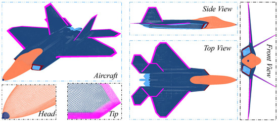
Figure 1.
Grid discrete diagram of a certain fighter aircraft model.
The discretized model is divided into M subdomains Ω1, Ω2, …, ΩM, each containing Ni discrete elements, resulting in the following matrix:
When i = j, Zij is the self-impedance matrix of region Ωi; when i ≠ j, Zij is the mutual impedance matrix between regions Ωi and Ωj.
The eigenfunction basis encompasses primary and secondary eigenfunctions. To solve for the primary eigenfunctions, each subdomain must be regarded as an independent region with the excitation source being the external incident field. This permits the construction of M independent primary eigenfunction solution equations:
in which denotes the self-impedance matrix of the extended subdomain i; denotes the matrix corresponding to the extended subdomain in the right excitation vector.
To determine the secondary basis functions, the coupling effects between subdomains must be considered. By using the primary basis functions as excitation sources for higher-order functions, the secondary basis functions for each subdomain can be derived:
In the equation, represents the principal characteristic basis function for the j-th subdomain, excluding the base subdomain. By performing LU decomposition on Equation (14) and directly computing its inverse, the M-1 sub-characteristic basis functions for the i-th subdomain can be obtained.
By solving Equations (13) and (14), we obtain one principal characteristic basis function and M-1 secondary characteristic basis functions. Subsequently, the currents within each subdomain are linearly superimposed to yield
In the equation, represents the weighted coefficient of the equation to be determined. Substituting Equation (15) into Equation (12) and multiplying both sides by yields the transpose, resulting in
In the formula, ZR is an M2 × M2 matrix, which can be expressed as
By directly solving Equation (16), the expansion coefficient matrix for the target current can be obtained. Substituting this into Equation (15) then yields the target current.
The far-field scattering pattern of a known target can be represented by a magnetic vector [36,37]:
In the equation, Es(r) represents the far-field scattering field; denotes the total target current obtained ahead; the r direction indicates the unit vector; can be expressed using the scattering angles θs and φs as follows:
Finally, the radar cross section can be calculated using the radar cross section equation:
2.3. Optimizing Model Construction and Validating Algorithm Accuracy
Considering both optimization speed and result reliability, this study selected the NASA Amygdala model for the inverse design of electromagnetic parameters of absorptive materials. The front end of the NASA almond-shaped model converges to a point, effectively simulating the aircraft’s snout. The mid-section smoothly transitions to a rear circle, producing a flattened ellipsoidal envelope that accurately represents the aircraft’s tail. Scaling this model proportionally enables an approximate simulation of the aircraft’s overall shape. The formulaic definition of the NASA almond-shaped profile is as follows [38,39].
In the formula, t ∈ [−0.41667, 0], ψ ∈ [−π, π], d = 9.936 inches.
In the formula, t ∈ [0, 0.58333], ψ ∈ [−π, π], d = 9.936 inches.
The recovered geometric shape of the amygdala was discretized into a mesh to obtain an electromagnetic grid. Radar cross section calculations were performed using the moment method [40,41,42] and the characteristic basis function method. The final results are shown in the figure. The accuracy of the characteristic basis function method closely mirrors that of the moment method, validating the algorithm’s precision. By comparing simulation results with actual measurements, the accuracy of the reconstructed amygdala model was verified to meet requirements. In Figure 2, “HH” and “VV” represent the horizontal and vertical polarization modes of the radar waves, respectively.
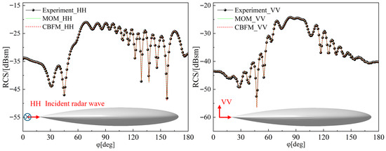
Figure 2.
Almond external shape and algorithm accuracy validation.
2.4. Inverse Design of Electromagnetic Parameters for RAM
The principal radar scatterers on an aircraft comprise the cockpit, air intakes, and the leading and trailing edges of the wings. These characteristics result in a comparatively elevated mean forward radar cross section, allowing radar systems to detect the aircraft with significant clarity. To tackle this issue, stealth design generally integrates form stealth methods with material stealth technologies to enhance and minimize the radar cross section. Nonetheless, attaining both superior stealth capabilities and an aerodynamic configuration presents difficulties. Consequently, absorptive materials appear as an excellent solution. This article applies a multi-objective optimization genetic algorithm for the inverse design of absorptive materials, intending to minimize the aircraft’s mean forward radar cross section.
The formula for calculating the mean radar cross section is as follows [43]:
Unlike the typical forward design technique of “material parameters → performance prediction,” this work utilizes a reversal strategy of “target performance → determining material parameters.” Starting with the desired outcome as a premise, the electromagnetic characteristics of the absorptive material are continually tuned by modifying the values of input parameters to achieve the requisite absorption performance of the absorptive material.
Multi-objective optimization is addressed through the integration of genetic algorithms, utilizing non-dominated sorting with an elite strategy and Pareto optimal solution sets [44,45]. Optimization efforts are primarily directed towards the following: the real and imaginary components of the dielectric constant, the real and imaginary components of the magnetic permeability, and the thickness of the absorber material are designated as optimization input parameters.
The NSGA-II genetic algorithm was employed for multi-objective optimization of the electromagnetic parameters (ε′, ε″, μ′, μ″) of radar-absorbing materials. The initial population was generated by selecting a diverse range of values for the real and imaginary parts of the dielectric constant and magnetic permeability. These values were constrained within the ranges defined by previous research [46,47,48,49,50,51], ensuring that the search space covered realistic and achievable material properties. Specifically, the initial ranges for the parameters were ε′ ∈ [4, 16], ε″ ∈ [0.27, 7.283], μ′ ∈ [0.8, 3.7], and μ″ ∈ [0.1, 5]. This initialization was designed to prevent the genetic algorithm from being restricted to a narrow subset of potential solutions.
Additionally, to mitigate the risk of the algorithm getting stuck in local optima, a population size of 100 individuals was employed, with a mutation probability of 0.2 to maintain diversity across generations. These settings, along with elitist selection, ensure that the best-performing solutions are preserved while maintaining sufficient population diversity, enabling the algorithm to explore the global optima effectively. Simulated binary crossover with a high crossover probability (0.9) was also used to recombine superior solutions.
During the specific numerical optimization run, considering engineering and weight constraints, we imposed a stringent constraint on d and fixed it at 1 mm. This choice reflects both the practical manufacturing and installation limitations of thin coatings in aircraft structures and correlates with the explicit lightweighting objective of this study. Therefore, the multi-objective search essentially focused on electromagnetic parameters while maintaining the thickness fixed at its minimal value. For the nonlinear search space defined by the four optimization variables ε′, ε″, μ′, and μ″, the following algorithm parameters were selected to reconcile computational accuracy and iteration efficiency, as shown in Table 1. Specifically addressing the computational sensitivity deriving from the long-wavelength characteristics of the P-band, a large population size was employed to ensure comprehensive coverage of the initial solution space.

Table 1.
Algorithm parameter selection table.
P-band radars are predominantly employed for long-range early warning. During missions, the forward sector of an aircraft encounters the most direct and severe detection threats, which determine the platform’s survivability. Therefore, we prioritize forward RCS reduction as the principal stealth metric, assigning it a higher weighting coefficient in the objective function. Figure 3 shows the flowchart for the inverse design of electromagnetic parameters for absorptive materials.
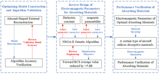
Figure 3.
Flowchart of electromagnetic parameter inverse design for absorbing materials.
3. Numerical Simulation Results and Analysis
3.1. Electromagnetic Parameters of Optimized Absorbing Materials
The previously developed amygdala model was proportionally scaled to function as the optimization model. Together with the optimization technique outlined previously, this method facilitated the electromagnetic parameter optimization design of the absorptive material. The convergence curve of the optimization process is presented in Figure 4. Each point in the figure denotes a single iteration of the optimization process. Specifically, as the algorithm iterates, the average reduction in forward RCS progressively stabilizes and approaches the target value, while the backward RCS is also effectively reduced.
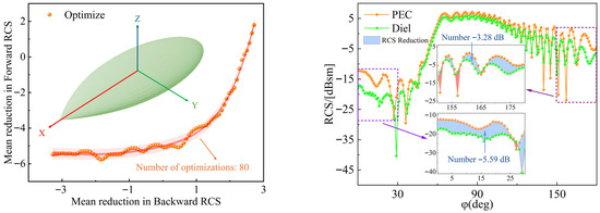
Figure 4.
Iterative Convergence curve for optimizing the mean reduction in RCS of absorbing materials.
Figure 4 illustrates that the quality of the optimal solution steadily enhances with increasing iterations until it ultimately converges at a global optimum. Although local optima may arise during initial generations, the algorithm effectively prevents this through suitable mutation and crossover procedures, thereby ensuring convergence to the global optimum.
Ultimately, after approximately 80 iterations, the algorithm converged, accurately determining the optimal electromagnetic parameters and material thickness. This process illustrates that, through diversified population initialization and carefully designed genetic operations, the NSGA-II algorithm can effectively avoid entrapment in local optima and successfully attain the desired optimization.
When the optimization point is located at the lower left (as shown in Figure 4), the mean forward radar cross section reaches the target value while the mean backward radar cross section is minimized. Analysis of Figure 4 indicates that applying the optimized absorptive material behind the amygdala reduces the mean forward radar cross section by approximately −5.59 dB and the mean backward radar cross section by approximately −3.28 dB.
The final optimal electromagnetic parameters of the absorptive material are εr = 3.3078 + j3.9018, μr = 2.3522 + j6.9519, with a material thickness d = 1 mm.
3.2. Performance Verification of Absorbing Materials
This work assesses the scattering reduction effectiveness of absorptive materials obtained via inverse design by applying them to a high-fidelity model of a representative fighter aircraft. RAM is applied to the leading and trailing edges of wing components, the intake duct inner cavity, and the lip area of the intake. An electromagnetic computational mesh is constructed from the reconstructed aircraft geometry, and RAM is assigned to the corresponding structural regions. The characteristic basis function method (CBFM) is then used to compute the aircraft’s RCS before and after RAM application.
The radar frequency is chosen at 425 MHz (within the P-band range of 300 MHz to 1 GHz). Incident elevation angles are set to −20°, −15°, −10°, −5°, 0°, 5°, and 10° (corresponding to Phi = 110°, 105°, 100°, 95°, 90°, 85°, and 80°, respectively), while azimuth angles sweep from 0° to 360°. In the figures, “Diel” denotes the case with the dielectric absorber coating, and “PEC” denotes the bare metallic configuration.
Figure 5 shows the forward RCS distribution surface of the aircraft model under horizontal polarization for incidence angles from −20° to 10°, comparing the cases with and without RAM. Figure 6 presents (top) the mean forward RCS reduction (for φ ∈ [0°, 30°]) at incidence angles of 5°, 0°, and −5° after coating; (middle) the mean forward RCS distributions at incidence angle 0° for both coated and uncoated configurations; and (bottom) the mean forward RCS reduction at incidence angles of 5°, 0°, and −5°.
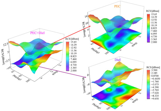
Figure 5.
RCS distribution surface diagram before and after RAM application for a certain aircraft model.
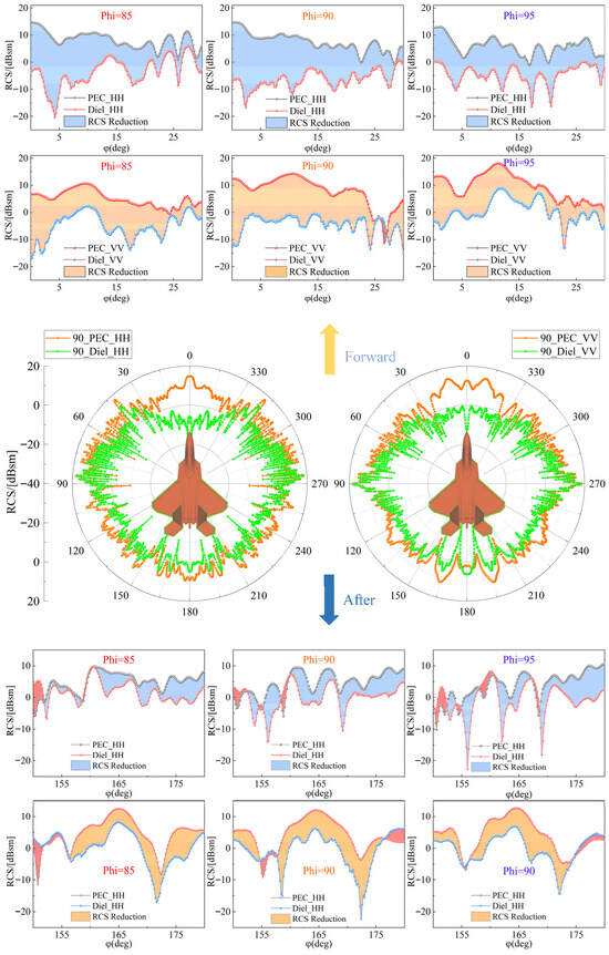
Figure 6.
RCS distribution of a certain aircraft model before and after application of RAM.
The upper portion of Figure 6 illustrates the reduction in mean forward RCS (corresponding to φ ∈ [0, 30]) for a specific aircraft model coated with radar-absorbing material, compared to its uncoated state, at radar wave incidence angles of 5°, 0°, and −5°. The middle section presents the omnidirectional RCS distribution for the aircraft with and without absorptive material coating at an incidence angle of 0°; the lower section illustrates the reduction in the aircraft’s rearward RCS (corresponding to φ ∈ [150, 180]) at incidence angles of 5°, 0°, and −5°. Based on the experimental data in Figure 6, applying absorptive materials to the leading and trailing edges of the wing components, the inner cavity of the intake duct, and the lip area of this aircraft type effectively suppresses its overall RCS. Particularly notable reductions are observed in the forward scattering direction. These results further validate the effectiveness of absorptive materials in dissipating electromagnetic wave energy at key scattering sources, providing robust support for enhancing stealth performance.
Analysis of the forward and backward RCS of the aircraft, processed using arithmetic averaging, is provided Table 2. Analysis of Table 2 data demonstrates that the electromagnetic properties of the RAM optimized by the inverse design method demonstrate superior absorption performance. After applying the RAM, the maximum decrease in the aircraft’s forward RCS in the P-band was −13.97 dB, with a minimum reduction of −8.89 dB. For the rearward radar cross section, the mean reduction reached a high of −5.03 dB and a minimum of −2.80 dB.
Table 2.
Forward and backward radar cross section reduction at different elevation angles and polarization modes.
3.3. Surface Current of a Certain Aircraft Before and After Applying Absorbing Materials
Under horizontal polarization radar conditions with an incidence angle of 0° and azimuth angle of 0°, Figure 7 illustrates the surface current distribution comparison for a specific aircraft model that is coated with and without absorptive materials. The top view employs a sectional representation of the airframe structure to more clearly reveal the current distribution characteristics within the intake duct cavity, emphasizing the variation patterns of surface currents within the cavity.
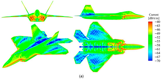
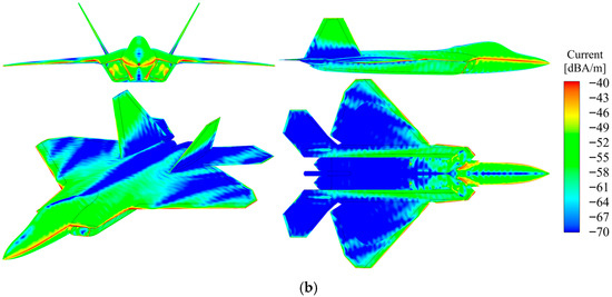
Figure 7.
RCS distribution of a certain aircraft before and after application of RAM under horizontal polarization. (a) PEC_HH_ Multi-view; (b) Diel_HH_ Multi-view.
The surface current distribution comparison for a specific aircraft model coated with and without absorptive materials is depicted in Figure 8. The radar utilizes vertical polarization, with an incidence angle of 0° and an azimuth angle of 0°. Red and yellow regions signify high-current areas, while blue regions denote low-current areas.
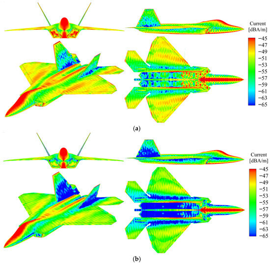
Figure 8.
RCS distribution of a certain aircraft before and after application of RAM under vertical polarization. (a) PEC_VV_ Multi-view; (b) Diel_VV_ Multi-view.
4. Discussion
At the leading and trailing margins of wing rib components, the sharpness of geometric boundaries induces significant current concentration. This phenomenon is predominantly attributed to edge diffraction and specular scattering effects, both of which substantially enhance scattering contributions in these regions, thereby increasing the radar cross section. Applying radar-absorbing materials to the wing leading edge and root effectively blunts these high-current-density zones. Specifically, RAM utilizes its dielectric or magnetic losses to dissipate incident electromagnetic energy as heat, thereby suppressing current concentration and reducing specular and edge scattering intensities. This substantially diminishes edge-induced RCS.
Additionally, the intake duct creates an internal cavity where radar waves undergo multiple reflections and standing waves upon entry. This causes current accumulation at the cavity opening and inner walls, producing high current density zones—a mechanism known as cavity scattering that substantially contributes to overall RCS. Applying absorptive coatings disrupts the cavity’s reflection paths, reduces standing wave ratios, and diminishes resonance intensity. RAM effectively diminishes the reflection coefficient, thereby decreasing electromagnetic energy accumulation within the cavity, suppressing current hotspots, and substantially diminishing cavity scattering’s contribution to RCS.
Overall, the absorptive material devised in this study effectively reduces the forward RCS of aircraft, enhancing their stealth capabilities. Future work may further investigate the influence of the absorptive material’s bandwidth, thickness, and dielectric/magnetic loss characteristics on RCS suppression performance, while investigating efficient broadband designs based on metamaterials, gradient impedance, or graded media.
Using Equations (1) and (2) in the text, we further calculated the optimized absorber material’s dielectric loss tangent tanδε = ε″/ε′ ≈ 1.18 and magnetic loss tangent tanδμ = ε″/ε′ ≈ 2.95. This quantitative result confirms that magnetic loss is the dominant energy dissipation mechanism for this ultra-thin material in the P-band. To resolve the physical limitations imposed by the 1 mm thickness, we introduce the Rozanov limit theory [52]. According to the physical constraint formula,
Achieving strong absorption at a thickness of 1 mm necessitates compensating for limited physical space through an exceptionally high imaginary part of complex magnetic permeability, μ″. The value of μ″ ≈ 6.95 obtained through inverse design in this paper is precisely the fundamental physical parameter enabling efficient energy conversion. This magnetically loss-dominated characteristic can be engineered by regulating the loading quantity and resonance response of magnetic fillers such as carbonyl iron (CIP). A low dielectric real part ε′ ≈ 3.3 aids in optimizing impedance matching and reducing direct surface reflection, while the extremely high magnetic imaginary part provides the primary attenuation mechanism.
5. Conclusions
Based on the impedance boundary condition and characteristic basis function method (CBFM), this paper constructs an optimization model with multiple objectives: minimizing the mean forward RCS reduction after applying absorptive material to the amygdala, minimizing the mean backward RCS, and minimizing the material thickness. The optimization problem treats the electromagnetic properties of the absorptive material and its thickness d as design variables. An upgraded NSGA-II genetic algorithm is applied for inverse design to produce greater absorptive performance in the P-band. Key conclusions are as follows:
- When the electromagnetic parameters of the absorptive material are εr = 3.3078 + j3.9018 and μr = 2.3522 + j6.9519, with a thickness d = 1 mm, applying this material to the surface of the amygdala reduces the mean forward RCS by approximately −5.59 dB and the mean backward RCS by approximately −3.28 dB.
- Applying the optimized absorptive material to the leading/trailing margins of an aircraft wing spar can effectively suppress edge diffraction and specular scattering, thereby reducing surface current density. Applying absorptive material to the inner cavity and lip of the intake duct can effectively attenuate radar wave reflections within the cavity, obtaining a reduction in radar cross section.
- After applying absorptive materials, the average forward RCS reduction in the P-band for the aircraft ranged from a maximum of −13.97 dB to a minimum of −8.89 dB. The average rearward RCS reduction ranged from a maximum of −5.03 dB to a minimum of −2.80 dB.
In summary, the inverse design process based on impedance boundary conditions and the eigenfunction method, combined with multi-objective NSGA-II optimization, enables the determination of material electromagnetic parameters and thickness configurations with excellent absorption properties under P-band conditions. This approach accomplishes significant RCS suppression effects in complex structures and cavity locations.
Author Contributions
Conceptualization, G.F. and J.H.; methodology, J.H.; software, J.H.; validation, J.H., G.F. and J.W.; formal analysis, J.H.; investigation, K.W.; resources, Q.G.; data curation, H.W.; writing—original draft preparation, J.H.; writing—review and editing, J.H.; visualization, G.F.; supervision, G.F.; project administration, J.H.; funding acquisition, G.F. All authors have read and agreed to the published version of the manuscript.
Funding
This research received no external funding.
Informed Consent Statement
Informed consent was obtained from all subjects involved in the study.
Data Availability Statement
The original contributions presented in this study are included in the article. Further inquiries can be directed to the corresponding author.
Conflicts of Interest
The authors declare no conflicts of interest.
References
- Narayan, S.; Sreeja, J.; Surya, V.V.; Sangeetha, B.; Nair, R.U. Radar absorbing structures using frequency selective surfaces: Trends and perspectives. J. Electron. Mater. 2020, 49, 1728–1741. [Google Scholar] [CrossRef]
- Gao, Y.; Yang, Q.; Ma, L.; Li, T.; Qi, Q.; Yang, T.; Meng, F. Radar-infrared compatible stealth technology in advanced nano-composite materials: Mechanisms and structural optimization. Mater. Today Nano 2024, 28, 100534. [Google Scholar]
- Kang, J.; Qu, Z.; Duan, J.; Jing, H.; Hao, J.; Song, C.; Wang, J.; Zhang, B. Multispectral flexible ultrawideband metamaterial absorbers for radar stealth and visible light transparency. Opt. Mater. 2023, 135, 113351. [Google Scholar] [CrossRef]
- Wang, X.; Shi, Y.; Yang, Q.; Xiang, H.; Bai, J. Study on Novel Radar Absorbing Grilles of Aircraft Engine Inlet Based on Metasurface Design Theory. Aerospace 2024, 11, 998. [Google Scholar] [CrossRef]
- Kaushik, N.; Singh, P.; Rana, S.; Sahoo, N.G.; Ahmad, F.; Jamil, M. Self-healable electromagnetic wave absorbing/shielding materials for stealth technology: Current trends and new frontiers. Mater. Today Sustain. 2024, 27, 100828. [Google Scholar] [CrossRef]
- Baek, S.M.; Lee, W.J.; Joo, Y.S. A study on a radar absorbing structure for aircraft leading edge application. Int. J. Aeronaut. Space Sci. 2017, 18, 215–221. [Google Scholar] [CrossRef]
- Sutrakar, V.K.; AP, K.; Kesharwani, S.; Bisariya, S. A Machine Learning Approach for Design of Frequency Selective Surface based Radar Absorbing Material via Image Prediction. In Proceedings of the 2025 6th International Conference on Control, Communication and Computing (ICCC), Thiruvananthapuram, India, 23–25 May 2025; IEEE: New York, NY, USA, 2025. [Google Scholar]
- Liu, Y.; Huang, X.; Yan, X. Performance optimization engineering of multicomponent absorbing materials based on machine learning. ACS Appl. Mater. Interfaces 2023, 15, 27056–27064. [Google Scholar] [CrossRef] [PubMed]
- Joy, V.; Anand, A.; Nidhi; Kumar, A.; Singh, H. A Surrogate Model for the Forward Design of Multi-Layered Metasurface-Based Radar Absorbing Structures. arXiv 2025, arXiv:2505.09251. [Google Scholar] [CrossRef]
- Yao, H.; Yang, J.; Li, H.; Xu, J.; Bi, K. Optimal design of multilayer radar absorbing materials: A simulation-optimization approach. Adv. Compos. Hybrid Mater. 2023, 6, 43. [Google Scholar] [CrossRef]
- Chen, X.; Liu, X.X.; Wang, X.J.; Liu, Y. Optimized design for multi-layer absorbing materials based on genetic algorithm. Adv. Mater. Res. 2013, 681, 324–328. [Google Scholar]
- Li, T.; Zhang, Y.; Tan, X. Study on the Design of Multi-Layer Absorbing Materials by Genetic Algorithm. Open Access Libr. J. 2023, 10, 1–6. [Google Scholar] [CrossRef]
- Zhou, M.; Chen, Y.; He, Y.; Yang, C. Calculation and optimization of P-band electromagnetic parameters of absorbing materials based on genetic algorithm. J. Aeronaut. Mater. 2024, 44, 102–110. [Google Scholar]
- Arslanagić, S.; Hansen, T.V.; Mortensen, N.A.; Gregersen, A.H. A review of the scattering-parameter extraction method with clarification of ambiguity issues in relation to metamaterial homogenization. IEEE Antennas Propag. Mag. 2013, 55, 91–106. [Google Scholar] [CrossRef]
- Chen, M.; Zhu, X.; Lei, H.; Fang, D.; Zhang, Z. Optimal design of broadband radar absorbing sandwich structure with circuit analog absorber core. Int. J. Appl. Mech. 2015, 7, 1550020. [Google Scholar] [CrossRef]
- Chambers, B.; Tennant, A. Optimised design of Jaumann radar absorbing materials using a genetic algorithm. IEE Proc. Radar Sonar Navig. 1996, 143, 23–30. [Google Scholar] [CrossRef]
- Choudhury, B. Metamaterial Inspired Electromagnetic Applications; Springer: New York, NY, USA, 2017; pp. 978–981. [Google Scholar]
- Sivakoti, K.K.; Basava, M.; Rao, V.B.; Sannidhi, B.M. Design optimization of radar absorbing materials using particle swarm optimization. Int. J. Appl. Metaheuristic Comput. (IJAMC) 2017, 8, 113–132. [Google Scholar] [CrossRef]
- Xiang, H.; Shi, Y.; Yang, Q.; Wang, X.; He, Y. Optimization design of honeycomb absorbing structure and its application in aircraft inlet stealth. Aerospace 2024, 11, 796. [Google Scholar] [CrossRef]
- Kasdorf, S.; Troksa, B.; Key, C.; Harmon, J.; Notaros, B.M. Advancing accuracy of shooting and bouncing rays method for ray-tracing propagation modeling based on novel approaches to ray cone angle calculation. IEEE Trans. Antennas Propag. 2021, 69, 4808–4815. [Google Scholar] [CrossRef]
- Tao, Y.; Lin, H.; Bao, H. GPU-based shooting and bouncing ray method for fast RCS prediction. IEEE Trans. Antennas Propag. 2009, 58, 494–502. [Google Scholar] [CrossRef]
- Deb, K.; Partap, A.; Agarwal, S.; Meyarivan, T. A fast and elitist multiobjective genetic algorithm: NSGA-II. IEEE Trans. Evol. Comput. 2002, 6, 182–197. [Google Scholar] [CrossRef]
- Rahimi, I.; Gandomi, A.; Nikoo, M.; Chen, F. A comparative study on evolutionary multi-objective algorithms for next release problem. Appl. Soft Comput. 2023, 144, 110472. [Google Scholar] [CrossRef]
- Li, M.; Ma, H.; Lv, S.; Wang, L.; Deng, S. Enhanced NSGA-II-based feature selection method for high-dimensional classification. Inf. Sci. 2024, 663, 120269. [Google Scholar] [CrossRef]
- Zhang, P.; Qian, Y.; Qian, Q. Multi-objective optimization for materials design with improved NSGA-II. Mater. Today Commun. 2021, 28, 102709. [Google Scholar] [CrossRef]
- Lv, L.; Shen, W. An improved NSGA-II with local search for multi-objective integrated production and inventory scheduling problem. J. Manuf. Syst. 2023, 68, 99–116. [Google Scholar]
- Zheng, W.; Doerr, B. Mathematical runtime analysis for the non-dominated sorting genetic algorithm II (NSGA-II). Artif. Intell. 2023, 325, 104016. [Google Scholar] [CrossRef]
- Cattelani, L.; Fortino, V. Improved NSGA-II algorithms for multi-objective biomarker discovery. Bioinformatics 2022, 38, ii20–ii26. [Google Scholar]
- Wang, Z.; Yang, T.; Zhou, L.; Hou, X.; Fang, Z.; Hou, Y. Current Progress and Challenges of Electromagnetic Wave Absorbing Materials at High Temperature. Adv. Sci. 2025, 12, e04286. [Google Scholar] [CrossRef]
- Lu, Z.; Liu, L.; Chen, Z.; Wang, C.; Zhu, X.; Lu, X. Progress in Electromagnetic Wave Absorption of Multifunctional Structured Metamaterials. Polymers 2025, 17, 2559. [Google Scholar] [CrossRef]
- Yang, J.; Li, Y.; Yi, D.; Li, M.; Huang, Y.; Tang, M.C. Review of progress in microwave electromagnetic stealth metasurfaces. Chin. J. Aeronaut. 2025, 38, 103711. [Google Scholar] [CrossRef]
- Feng, Y.; Liang, M.; Zhao, X.; You, R. Fabrication and modulation of flexible electromagnetic metamaterials. Microsyst. Nanoeng. 2025, 11, 14. [Google Scholar] [CrossRef]
- Tzarouchis, D.C.; Koutsoupidou, M.; Sotiriou, I.; Dovelos, K.; Rompolas, D.; Kosmas, P. Electromagnetic metamaterials for biomedical applications: Short review and trends. EPJ Appl. Metamater. 2024, 11, 7. [Google Scholar] [CrossRef]
- Du, Y.; Liu, Y.; Wang, A.; Kong, J. Research progress and future perspectives on electromagnetic wave absorption of fibrous materials. iScience 2023, 26, 107873. [Google Scholar] [CrossRef] [PubMed]
- Huang, J.; Bai, Y.; Liu, Y.; Wang, Y.; Feng, G. Two Calculation Methods for Flight Envelope Oriented Towards Fighter Aircraft. Mod. Def. Technol. 2026, 1–18. [Google Scholar]
- Dodin, I.Y.; Ruiz, D.E.; Yanagihara, K.; Zhou, Y.; Kubo, S. Quasioptical modeling of wave beams with and without mode conversion. I. Basic theory. Phys. Plasmas 2019, 26, 072110. [Google Scholar] [CrossRef]
- Achouri, K.; Salem, M.A.; Caloz, C. General metasurface synthesis based on susceptibility tensors. IEEE Trans. Antennas Propag. 2015, 63, 2977–2991. [Google Scholar] [CrossRef]
- Key, C.; Harmon, J.; Notaros, B.M. Discrete surface Ricci flow for general surface meshing in computational electromagnetics using iterative adaptive refinement. IEEE Trans. Antennas Propag. 2020, 69, 332–346. [Google Scholar] [CrossRef]
- Simpson, R.N.; Liu, Z.; Vázquez, R.; Evans, J.A. An isogeometric boundary element method for electromagnetic scattering with compatible B-spline discretizations. J. Comput. Phys. 2018, 362, 264–289. [Google Scholar] [CrossRef]
- Tucek, J.; Capek, M.; Jelínek, L.; Sigmund, O. Density-based topology optimization in method of moments: Q-factor minimization. IEEE Trans. Antennas Propag. 2023, 71, 9738–9751. [Google Scholar] [CrossRef]
- Petek, M.; Rivero, J.; Vásquez, J.A.T.; Valerio, G.; Quevedo-Teruel, O.; Vipiana, F. Method of moments for the dispersion modeling of glide-symmetric periodic structures. IEEE Trans. Antennas Propag. 2023, 72, 756–766. [Google Scholar] [CrossRef]
- Harmon, J.J.; Branislav, M.N. Accelerated adaptive error control and refinement for SIE scattering problems. IEEE Trans. Antennas Propag. 2022, 70, 9497–9510. [Google Scholar] [CrossRef]
- Grieco, G.; Stoffelen, A.; Verhoef, A.; Vogelzang, J.; Portabella, N. Analysis of data-derived seawinds normalized radar cross-section noise. Remote Sens. 2022, 14, 5444. [Google Scholar] [CrossRef]
- Mohammadi, A.; Custódio, A.L. A trust-region approach for computing Pareto fronts in multiobjective optimization. Comput. Optim. Appl. 2024, 87, 149–179. [Google Scholar] [CrossRef]
- Hoseinpoor, N.; Ghaznavi, M. A flexible objective-constraint approach and a new algorithm for constructing the Pareto front of multiobjective optimization problems. Acta Math. Sci. 2024, 44, 702–720. [Google Scholar] [CrossRef]
- Kim, S.-H.; Lee, S.; Zhang, Y.; Park, S.; Gu, J. Carbon-based radar absorbing materials toward stealth technologies. Adv. Sci. 2023, 10, 2303104. [Google Scholar] [CrossRef] [PubMed]
- Madiha, F.M.; Raba’ah, S.A.; Ismayadi, I.; Farah, D.M. A review on electromagnetic microwave absorption properties: Their materials and performance. J. Mater. Res. Technol. 2022, 20, 2188–2220. [Google Scholar] [CrossRef]
- Gama, A.M.; Rezende, M.C. Complex permeability and permittivity variation of radar absorbing materials based on MnZn ferrite in microwave frequencies. Mater. Res. 2013, 16, 997–1001. [Google Scholar] [CrossRef]
- Semenenko, V.N.; Chistyaev, V.; Politiko, A.; Kibets, S.G.; Kisel, V.N.; Gallagher, C.P.; Mckeever, C.; Hibbins, A.; Ogrin, F.; Sambles, J. Complex permittivity and permeability of composite materials based on carbonyl iron powder over an ultrawide frequency band. Phys. Rev. Appl. 2021, 16, 014062. [Google Scholar] [CrossRef]
- Xie, Q.; Chen, Y.; Rao, H.; An, X.; Nan, K.; Wang, Y. Two birds with one stone: Integrating multidimensional heterointerfaces with abundant nitrogen sites for ultrathin broadband microwave absorber. Chem. Eng. J. 2025, 510, 161603. [Google Scholar] [CrossRef]
- Pei, R.; Chen, Y.; Rao, H.; Jin, W.; Nan, K.; Wang, Y. In Situ Metal-Catalyzed Scale Modulation to Implement Electromagnetic Response for Ultra-Wideband Microwave Absorbers. Carbon 2025, 244, 120692. [Google Scholar] [CrossRef]
- Weber, M.J.G. On Rozanov’s Theorem and strenghtened asymptotic uniform distribution. arXiv 2022, arXiv:2209.12228. [Google Scholar] [CrossRef]


Disclaimer/Publisher’s Note: The statements, opinions and data contained in all publications are solely those of the individual author(s) and contributor(s) and not of MDPI and/or the editor(s). MDPI and/or the editor(s) disclaim responsibility for any injury to people or property resulting from any ideas, methods, instructions or products referred to in the content. |
© 2026 by the authors. Licensee MDPI, Basel, Switzerland. This article is an open access article distributed under the terms and conditions of the Creative Commons Attribution (CC BY) license.