Abstract
A reflective in-fiber liquid microsphere whispering gallery mode (WGM) resonator based on a Y-waveguide coupler is proposed and experimentally demonstrated. The sphere resonator is introduced inside a single-mode fiber (SMF) by using femtosecond laser micromachining and fusion splicing. A Y-waveguide coupler is fabricated with femtosecond laser direct writing, which is used to simultaneously excite and collect the WGM field through evanescent field coupling. High-index liquids are filled into the sphere through a laser-drilled channel to form a liquid microsphere where the WGM resonation takes place. The WGM resonator is sensitive to the refractive index (RI) of the filled liquids, and a RI sensitivity of 439 nm/RIU is achieved in an index range from 1.672 to 1.692. The liquid microsphere resonator is also sensitive to temperature, with a sensitivity of −307.1 pm/°C obtained. The microsphere resonator is small in size and robust, which has broad application prospects in the field of food and the chemical industry.
1. Introduction
Optical whispering gallery technology [1] has attracted widespread attention in recent years. Whispering Gallery Mode microcavities, known for their high Q-factor, small mode volume, and low loss, have found applications in various fields such as nonlinear optics, low-threshold lasers, filters, and optical frequency combs [2,3,4,5,6,7]. WGM resonators have been proposed in different forms, such as microspheres, microdisks, and microbottles [8,9,10].
Light is typically coupled into WGM cavities through evanescent waves, and the coupling method is crucial for enhancing the Q-factor and ensuring the stability of whispering gallery mode (WGM) devices. Although tapered fiber coupling [11,12] offers advantages such as high coupling efficiency and flexible adjustment, the tapered fiber has an extremely thin waist, making it fragile and susceptible to external environmental influences and unstable without additional protection methods. Prism coupling [13] offers strong resistance to environmental interference and flexible tuning, but the prism coupling setup is relatively large and bulky, making it inconvenient to be applied in compact or miniaturized situations. End-face coupling [14] has a simple structure and is easy to integrate, but it suffers from low coupling efficiency and is susceptible to various factors, such as unevenness of the fiber end face and coupling angles. In recent years, coupling structures have been continuously optimized. For instance, a micro-ring resonator structure was fabricated on the tip of a single-mode fiber using two-photon polymerization technology [15], where the micro-ring structure is used to excite whispering gallery modes and achieve refractive index sensing applications. Additionally, through the advanced 3D manufacturing technology of two-photon lithography, an optical microsystem is fabricated on the end facet of a multicore optical fiber [16], and whispering gallery modes with high quality factors are observed.
On the other hand, WGM resonators have also been demonstrated with solid polymer spheres. These resonators are formed by introducing solid microspheres into the capillary interior to achieve high-Q-factor WGM configurations. Commonly used methods include fixing solid microspheres inside the capillary using UV adhesive [17,18], where light from optical fibers can be coupled into the resonators. However, the use of UV adhesive introduces additional optical losses, leading to measurement errors. Shi et al. demonstrated a transmission bandpass coupler attached to an optical fiber, which is composed of paired curved waveguides etched onto a D-shaped fiber [19,20]. This structure achieves the bandpass function by utilizing embedded polymer microsphere resonators. However, during the femtosecond laser etching process, debris is generated, which affects the coupling efficiency, and the encapsulation of the polymer microspheres also increases the loss of the structure.
In this paper, an in-fiber microsphere whispering gallery mode (WGM) resonator based on a Y-waveguide coupler is proposed and experimentally demonstrated. Femtosecond laser micromachining and fusion splicing are used to create a sphere resonator in a single-mode fiber, followed by the infiltration of high-index liquids. A Y-waveguide coupler is introduced close to the sphere, which excites and collects the WGM field through evanescent field coupling. The WGM resonator is sensitive to the refractive index of the filled liquids, and a RI sensitivity of 439 nm/RIU is achieved in an index range from 1.668 to 1.692. On the other hand, a temperature sensitivity of −307.1 pm/°C is obtained. Such a device is robust in structure and small in size, which can find applications in the field of chemical sensing.
2. Fabrication and Principle of the Sensor
The schematic diagram of the WGM microsphere resonator structure based on a Y-shaped waveguide is shown in Figure 1. The fabrication process of the WGM resonator device involves the following steps. First, a single-mode fiber (SMF) with a flat-cut end face is fixed on a high-precision three-dimensional displacement platform using a fiber holder. A femtosecond laser (Spectra physics, Irvine, CA, USA, Solstice, 100 fs @800 nm, 1 kHz) is focused on the core of the fiber end face through a 10× objective with a numerical aperture (NA) of 0.25. A CCD camera is used for the observation of the laser micromachining. A pulse energy of 2 µJ is used to drill a micro-hole in the core at the fiber end face, as shown in Figure 2a. Next, the processed fiber sample is fusion-spliced to another single-mode fiber. A microsphere cavity is formed through fusion discharge in the splicer (Figure 2b), and the diameter of the formed microsphere cavity is measured to be 44 µm. After that, the Y-shaped waveguide is introduced. An oil-immersion objective with a numerical aperture of 1.25 and a magnification of 100× is used in the writing of the Y-waveguide. To fabricate the Y-waveguide, the laser is focused on the fiber core, followed by a circular motion with a speed of 1 µm/s. The radius of the circular motion is set to be 15 µm, ensuring that the waveguide is precisely tangent to the microsphere cavity. Then, another mirror-symmetric circular waveguide is fabricated to form the Y-waveguide, as shown in Figure 2d. Subsequently, the fiber sample is rotated 90° along its axis, and a micro-channel is drilled to the microsphere cavity (Figure 2e), using a 10× objective and pulse energy of 25 µJ. Finally, high-refractive-index liquid is filled into the microsphere cavity through the micro-channel (Figure 2f).
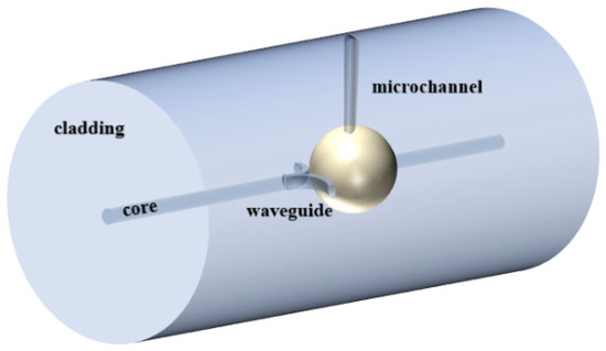
Figure 1.
Schematic diagram of the WGM microsphere resonator.
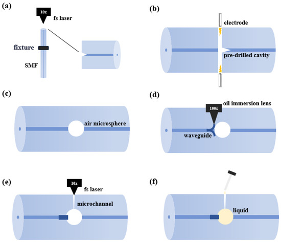
Figure 2.
Fabrication process of the optical fiber WGM resonator (a) Laser processing of a micro-hole on the fiber end face. (b,c) Formation of the microsphere cavity through fusion discharge in the fusion splicer. (d) Inscription of the Y-shaped waveguide. (e) Fabrication of a micro-channel above the microsphere cavity. (f) Filling the microsphere cavity with a high-refractive-index liquid.
Figure 3a is the microscopic picture of the device after writing the Y-waveguide, and Figure 3b shows the side-view microscope image of the WGM cavity with a micro-channel introduced and high-index liquids infiltrated. The diameter of the microsphere is approximately 44 µm.
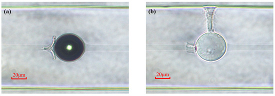
Figure 3.
(a) Laser-inscribed Y-shaped waveguide. (b) Laser-drilled micro-channel and filled with high-refractive-index liquid.
The propagation path of light in the proposed WGM resonator device is shown in Figure 1. When light from the fiber core reaches the Y-shaped waveguide, a portion of the light is coupled into the liquid microsphere through an evanescent wave at the tangent point between the waveguide and the microsphere. The light then undergoes total internal reflection at the surface of the microsphere. When light of a specific wavelength satisfies the phase-matching condition, WGM resonance is excited, as illustrated in Figure 4. After the propagation in the microsphere, the light is then coupled back to the fiber core through the Y-waveguide. On the other hand, some of the incident light is reflected by the front and back surfaces of the microsphere, forming a Fabry–Pérot (F–P) interference, as also shown in Figure 4.
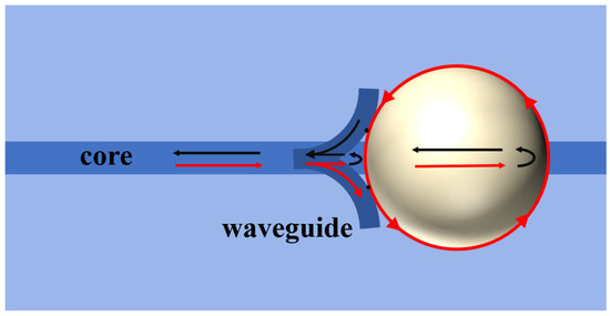
Figure 4.
The optical path of the WGM microsphere resonator and the F–P resonator.
For the liquid-filled microsphere WGM resonator, the resonant wavelength is approximately defined by,
where λ represents the resonant wavelengths, m is the resonant order, neff is the effective refractive index in the resonance cavity, and D is the diameter of the microsphere. The free spectral range (FSR) of the WGM spectrum is,
For the F–P cavity, the FSR is given by the following equation,
where n is the refractive index of the liquid.
3. Results and Discussion
During the fabrication process, the reflection spectrum of the device is monitored by a broadband source (BBS) and an optical spectrum analyzer (OSA) (YOKOGAWA-AQ6370C, Tokyo, Japan) with a resolution of 0.02 nm. After the air cavity and Y-type waveguide are fabricated, and before the micro-channel and liquids are introduced, the reflection spectrum of the device is collected and plotted in Figure 5. At this point, the liquid has not been infiltrated, and there is only the F–P interference signal in the spectrum. By taking the value of n and L into Equation (3), the FSR of the F–P interference is calculated to be 27.3 nm, which is close to the measured value of 27.7 nm.
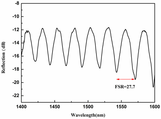
Figure 5.
The reflection spectrum of the WGM resonator after the air cavity and Y-waveguide is fabricated.
When the micro-channel is fabricated, and high-index liquid is introduced to the cavity, the reflection spectrum transforms into Figure 6a. Due to the presence of the high-index liquids, total internal reflection takes place at the liquid–silica boarders, and WGM is excited. Figure 6a gives the reflection spectrum of the resonant cavity after a high refractive index liquid is filled. The RI value of liquids infiltrated in the cavity is 1.692. The diameter of the microsphere is 44 μm. From Figure 6a, we can see that the free spectrum range is narrower, and the spectrum is no longer a simple F–P interference pattern. To analyze the component of the spectrum in Figure 6a, a fast Fourier transform (FFT) is applied, and the results are plotted in Figure 6b. The peaks at 0.059 nm−1, 0.0899 nm−1, 0.14985 nm−1, and 0.244 nm−1 correspond to FSR values of 16.683 nm, 11.12 nm, 6.67 nm, and 4.09 nm, respectively. According to Figure 4, when high-index liquids are infiltrated into the sphere, WGM resonance as well as F–P interference take place in the device, and both contribute to the reflection spectrum. The FSR of the F–P interference can be calculated by taking the index value of the liquid into Equation (3) and is estimated to be 16.1 nm, which is close to the 16.683 nm derived from the measured spectrum. Using Equation (2), the FSR of the WGM can be calculated to be 10.27 nm, which is close to the 11.12 nm from the spectrum. This small discrepancy can be caused by the uncertainty in the measurement of the sphere radius. There are also other components (6.67 nm and 4.09 nm), which might result from the Fano line shape of the WGM spectrum. The asymmetric Fano line shape of the WGM resonance is caused by the coupling interference between WGM and the waveguide modes.
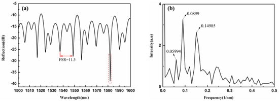
Figure 6.
(a) The reflection spectrum of the resonant cavity after filling with a high refractive index liquid (b) FFT of the reflection spectrum.
The formula for calculating the Q-factor of the microcavity is defined as:
where λ is the resonance wavelength, and Δλ is the full width at half-maximum (FWHM) value of the resonance wavelength.
Figure 7 shows a magnified view of the dashed box in Figure 6. The resonance dip wavelength is 1581.8 nm, with a Δλ of 0.86 nm. Using Equation (4), the calculated Q-factor of the WGM resonator is 1.839 × 10³.
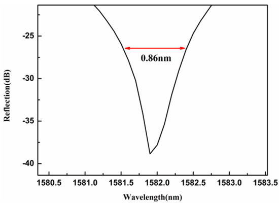
Figure 7.
Enlarged view of a dip in the reflection spectrum of the WGM microsphere resonator.
To further verify that the whispering gallery phenomenon arises from the combined effects of the laser-inscribed Y-waveguide and the high-refractive-index liquid filled into the microsphere cavity, samples with microsphere cavities of similar size but without the Y-waveguide are fabricated. Figure 8a shows the reflection spectrum of a resonator device without the waveguide. After laser-processing the micro-channel and filling the microsphere cavity with a high-refractive-index liquid (n = 1.692), the reflection spectrum is shown in Figure 8b. Analysis using Equations (1) and (3) confirms that only the Fabry-Pérot (F–P) mode exists in the resonator device before and after filling with the refractive-index liquid. This further demonstrates that the Y-shaped waveguide inscribed by the laser plays a crucial role in exciting the whispering gallery mode in the liquid-filled microsphere cavity.
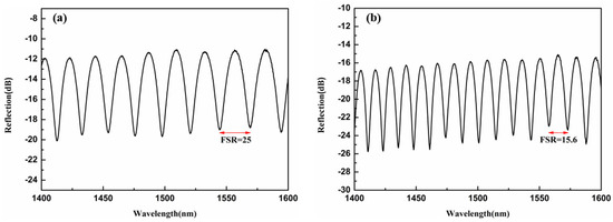
Figure 8.
(a) The reflection spectrum of the microsphere resonator without waveguide engraving, (b) Reflection spectrum of the microsphere resonator without inscribed waveguides filled with high-refractive-index liquid.
Considering that the infiltrated high-refractive-index liquid has a high thermo-optic coefficient, the device is expected to exhibit a sensitive spectral response to temperature. To verify this, a temperature sensing experiment was conducted, with the experimental setup illustrated in Figure 9. A tube furnace (LCO 102) with a temperature accuracy of 0.1 °C was used as the heating device, and the WGM resonator was placed inside it. The temperature increased from 30 °C to 44 °C with an increment of 2 °C. After reaching and stabilizing at each target temperature, the reflection spectrum is recorded.
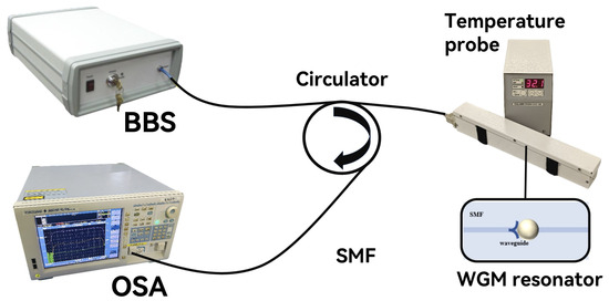
Figure 9.
Experimental set-up for temperature sensing.
As shown in Figure 10a, the resonant spectrum shifts toward shorter wavelengths as the temperature rises. Due to the negative thermo-optic coefficient of the liquid, the liquid RI will decrease when the temperature rises, and become closer to the RI value of the silica. In this way, the total internal reflection at the liquid-silica boarder is weaker, which leads to a smaller extinction ratio at higher temperatures, as we observed in Figure 10a. Figure 10b displays the resonant wavelengths corresponding to different temperature values within the measured range, demonstrating a strong linear relationship with a linearity of 96.7%. The obtained temperature sensitivity is −307.1 pm/°C. The temperature-induced change in the liquid RI significantly affects the WGM resonance wavelength. This effect can be described by the following equation,
where dn/dT is the thermo-optic coefficient of the liquid, and dD/dT is the thermal expansion coefficient. The latter is in the order of 10−7/°C, which is significantly smaller than the thermo-optic coefficient, making the thermal expansion effect negligible. This sensitivity is much higher than that of WGM resonators encapsulated with solid microspheres [21].
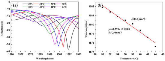
Figure 10.
(a) The reflection spectrum changes with temperature. (b) The dip wavelength shift versus temperature.
The reflection spectrum of the WGM resonator proposed in this paper is affected not only by external environmental temperature but also by the refractive index of the liquid within the microsphere cavity. The RI variation in the infiltrated liquid causes the effective refractive index in the resonance cavity to change, resulting in a change in the resonance condition, and finally causing a shift in the resonance wavelength, which can be expressed as,
where Δneff is the change in the effective index in the resonance cavity. We experimentally investigated the spectral response of the device to changes in the liquid RI in the microsphere cavity. To facilitate liquid replacement, a micro-channel was fabricated through the cavity perpendicular to the Y-shaped waveguide plane, enabling the inflow and outflow of high-refractive-index liquids. High RI liquid with index value from 1.672 to 1.692 is infiltrated into the cavity through the micro-channel. At lower RIs, the index difference between the core and liquid cavity will be smaller, and the resonant dips will be difficult to distinguish. The increment of RI is 0.004. The spectrometer reflectance spectrum at each index value is recorded. The fiber device was rinsed with methanol carefully each time after the recording of the spectrum.
Figure 11a shows the spectral response of the device as the liquid RI is increased from 1.672 to 1.692. It reveals a red shift in the spectrum with increasing liquid RI. Meanwhile, the Q-factor becomes higher as RI increases. Figure 11b illustrates the resonant wavelengths corresponding to different RI values within the measured range, demonstrating a strong linear relationship with a linearity of 97.3%. The achieved RI sensitivity is 439 nm/RIU. This device can detect liquid index variations in the high-RI range, showing potential for applications in food and chemical industries. In the future, expanding the RI measurement range to lower values could be achieved by using special optical fibers.
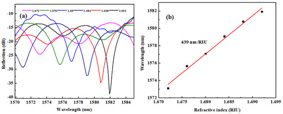
Figure 11.
(a) The reflection spectrum changes with RI. (b) The dip wavelength shift versus RI.
4. Conclusions
In summary, a whispering gallery mode (WGM) microsphere resonator based on a Y-waveguide is proposed and demonstrated. This resonator is fabricated by creating a spherical air micro-cavity within a single-mode fiber using femtosecond laser micromachining and fusion splicing technology. A Y-waveguide is directly inscribed into the single-mode fiber using a femtosecond laser through a 100× oil-immersion objective. Subsequently, micro-channel processing enables liquid filling into the microsphere cavity. Light from the fiber core couples into the microsphere via evanescent wave interaction along the tangential direction of the Y-shaped waveguide, exciting the optical whispering gallery mode within the microsphere cavity. The light is then guided back into the fiber core through the other tangential arm of the Y-shaped waveguide. The Q-factor of the liquid microsphere resonator is 1.839 × 10³. Within the RI range of 1.672 to 1.692, the RI sensing sensitivity of 439 nm/RIU is achieved. Temperature sensitivity of −307.1 pm/°C is obtained in the temperature range of 30 °C to 44 °C. The proposed device is compact, highly sensitive, and stable, which shows potential applications in fields such as the chemical and medical industries.
Author Contributions
Investigation, L.Z.; Methodology, R.C.; Project administration, S.L.; Validation, L.M.; Writing—original draft, L.Z.; Writing—review and editing, Z.H. All authors have read and agreed to the published version of the manuscript.
Funding
This work was supported in part by the National Natural Science Foundation of China under Grant 12004290 and Grant 51909195, in part by Hubei Provincial Natural Science Foundation of China under Grant 2020CFB251, in part by Scientific Research Project of Education Department of Hubei Province under Grant Q20181501 and Grant Q20191512, in part by State Key Laboratory of Advanced Optical Communication Systems Networks under Grant 2020GZKF007.
Institutional Review Board Statement
Not applicable.
Informed Consent Statement
Not applicable.
Data Availability Statement
Data are available from the corresponding author and can be provided upon appropriate request.
Conflicts of Interest
The authors declare no conflicts of interest.
References
- Yang, Y.; Wang, Z.; Zhang, X.; Zhang, Q.; Wang, T. Recent progress of in-fiber WGM microsphere resonator. Front. Optoelectron. 2023, 16, 10. [Google Scholar] [CrossRef]
- Tang, Z.; Zheng, H.; Wang, Y.; Wang, R.; Qiu, Z.; Shen, Y.; Zhou, J.; Su, S.; Li, L.; Zhu, H. Ultralow-threshold six-photon-excited upconversion lasing in a plasmonic microcavity. Nanoscale 2022, 14, 7589–7595. [Google Scholar] [CrossRef]
- Guo, J.; Li, L.; Liu, B.; Tang, Y.; Qin, L.; Deng, Z.; Lou, Z.; Hu, Y.; Teng, F.; Hou, Y. Ultrafast fabrication of cavity-controlled perovskite-crystallites by a spin-coating method for microlasers. J. Mater. Chem. C Mater. Opt. Electron. Devices 2023, 11, 3030–3038. [Google Scholar] [CrossRef]
- Chen, W.; Wang, L.; Liu, R.; Shen, H.; Du, J.; Fan, F. Self-Assembled and Wavelength-Tunable Quantum Dot Whispering-Gallery-Mode Lasers for Backlight Displays. Nano Lett. 2023, 23, 437–443. [Google Scholar] [CrossRef]
- Wang, P.; Madugani, R.; Zhao, H.; Yang, W.; Ward, J.M.; Yang, Y.; Farrell, G.; Brambilla, G.; Nic Chormaic, S. Packaged Optical Add-Drop Filter Based on an Optical Microfiber Coupler and a Microsphere. IEEE Photonics Technol. Lett. 2016, 28, 2277–2280. [Google Scholar] [CrossRef]
- Trocha, P.; Karpov, M.; Ganin, D.; Pfeiffer, M.H.; Kordts, A.; Wolf, S.; Krockenberger, J.; Marin-Palomo, P.; Weimann, C.; Randel, S.; et al. Ultrafast optical ranging using microresonator soliton frequency combs. Science 2018, 359, 887–891. [Google Scholar] [CrossRef]
- Liang, W.; Savchenkov, A.A.; Matsko, A.B.; Ilchenko, V.S.; Seidel, D.; Maleki, L. Generation of near-infrared frequency combs from a MgF_2 whispering gallery mode resonator. Opt. Lett. 2011, 36, 2290–2292. [Google Scholar] [CrossRef] [PubMed]
- Bai, X.Q.; Wang, D.N. Whispering-gallery-mode excitation in a microsphere by use of an etched cavity on a multimode fiber end. Opt. Lett. 2018, 43, 5512–5515. [Google Scholar] [CrossRef] [PubMed]
- Schweinsberg, A.; Hocdé, S.; Lepeshkin, N.N.; Boyd, R.W.; Chase, C.; Fajardo, J.E. An environmental sensor based on an integrated optical whispering gallery mode disk resonator. Sens. Actuators B Chem. 2007, 123, 727–732. [Google Scholar] [CrossRef]
- Ding, M.; Senthil Murugan, G.; Brambilla, G.; Zervas, M.N. Whispering gallery mode selection in optical bottle microresonators. Appl. Phys. Lett. 2012, 100, 839. [Google Scholar] [CrossRef]
- Heshmati, S.; Abedi, K.; Darvish, G. High-Q microsphere integrated with a tapered fiber suitable for biosensing applications. Opt. Quantum Electron. 2019, 51, 273. [Google Scholar] [CrossRef]
- Dong, Y.; Wang, K.; Jin, X. Package of a dual-tapered-fiber coupled microsphere resonator with high Q factor. Opt. Commun. 2015, 350, 230–234. [Google Scholar] [CrossRef]
- Vogt, D.W.; Jones, A.H.; Schwefel, H.G.; Leonhardt, R. Prism coupling of high-Q terahertz whispering-gallery-modes over two octaves from 0.2 THz to 1.1 THz. Opt. Express 2018, 26, 31190–31198. [Google Scholar] [CrossRef] [PubMed]
- Wang, D.N.; Chen, W.P.; Liu, J.; Xu, B.; Wang, Z.K.; Zhao, C.L. Whispering gallery mode microsphere resonator with microsphere-microsphere coupling. Opt. Fiber Technol. 2018, 46, 147–151. [Google Scholar] [CrossRef]
- Halendy, M.; Ertman, S. Whispering-Gallery Mode Micro-Ring Resonator Integrated with a Single-Core Fiber Tip for Refractive Index Sensing. Sensors 2023, 23, 9424. [Google Scholar] [CrossRef]
- Zhang, S.; Tang, S.J.; Feng, S.; Xiao, Y.F.; Cui, W.; Wang, X.; Sun, W.; Ye, J.; Han, P.; Zhang, X.; et al. High-Q Polymer Microcavities Integrated on a Multicore Fiber Facet for Vapor Sensing. Adv. Opt. Mater. 2019, 7, 1900602.1–1900602.6. [Google Scholar] [CrossRef]
- Rao, J.; Wang, D.N.; Xu, B.; Yang, K. A Reflective Whispering Gallery Mode Microsphere Resonator Integrated With a Thick-Wall Capillary Tube. IEEE Photonics Technol. Lett. 2024, 36, 409–412. [Google Scholar] [CrossRef]
- Wu, J.; Wang, D.N.; Zhao, C.L. Whispering gallery mode resonator based on dual microspheres in an expanded hollow sphere cavity of capillary tube. Opt. Laser Technol. 2023, 157, 108646. [Google Scholar] [CrossRef]
- Shi, L.; Wang, Q.; Zhu, T. A Fiber-Attached Coupler for Transmission Bandpass Whispering Gallery Mode Resonator. J. Light. Technol. 2021, 39, 6. [Google Scholar] [CrossRef]
- Shi, L.; Wang, Q.; Luo, J.; Zhu, T. In-fiber wavelength-selective reflector based on Y-junction coupled whispering gallery mode resonator. Opt. Lasers Eng. 2021, 137, 106329. [Google Scholar] [CrossRef]
- Hua, K.; Wang, D.N. A Whispering Gallery Mode Microsphere Resonator Integrated With Angle Polished Multimode Fiber. J. Light. Technol. 2021, 39, 4049–4054. [Google Scholar] [CrossRef]


Disclaimer/Publisher’s Note: The statements, opinions and data contained in all publications are solely those of the individual author(s) and contributor(s) and not of MDPI and/or the editor(s). MDPI and/or the editor(s) disclaim responsibility for any injury to people or property resulting from any ideas, methods, instructions or products referred to in the content. |
© 2025 by the authors. Licensee MDPI, Basel, Switzerland. This article is an open access article distributed under the terms and conditions of the Creative Commons Attribution (CC BY) license.