Abstract
In this work, a broadband polarization-sensitive metamaterial absorber (MA) based on a plasmonic bilayer nanostructure array is designed and numerically investigated. The proposed polarization-sensitive MA exhibits a high average absorption of 91.9% for TM-polarized light from 500 nm to 2000 nm and as low as 11.6% for TE-polarized light. Furthermore, a plasmonic germanium photodetector (PD) functionalized by the proposed polarization-sensitive MA is constructed and the potential application of distinguishing TM- and TE-polarized light is explored in simulation. The calculated results demonstrate that the photo-current difference generated by the PD under TM- and TE-polarized light excitation can reach 11.9 μA. The proposed broadband polarization-sensitive MA can be used in many fields, including polarization detection and other polarization-sensitive optoelectronic devices.
1. Introduction
A metamaterial is a type of artificially prepared material that does not exist in nature. Their permittivity and permeability can be modulated by optimizing the pattern shape and geometric parameters of the periodic unit atom that consists of the metamaterial. Owing to their excellent advantages, metamaterials have realized many novel phenomena, such as planar metalens [1,2], negative refractive index [3], and electromagnetically induced transparency [4], etc. Among them, metamaterial absorbers (MAs), proposed first by Landy and his team in 2008 [5], are a sorts of devices that convert electromagnetic energy into other forms of energy, used extensively in many fields such as solar harvesting [6], sensing [7,8], radiation cooling [9], and thermal images [10], etc. Due to their plentiful applications, MAs have been carried out in many various wavelength bands, including visible, near-infrared, mid-infrared, as well as longer wavelength regions. Meanwhile, various operating wavelength bandwidths of MAs have also been developed rapidly, such as single bandwidth, multi-bandwidth, narrow bandwidth, as well as wide bandwidth, etc. Traditional MAs are generally designed to be isotropic (i.e., polarization-insensitive), owing to their widespread application in energy harvesting. However, polarization-sensitive MAs are as equally important as the polarization-insensitive ones because the polarization state of light carries momentous information from target objects when they interact with each other. So far, polarization-sensitive MAs have been extensively used in fields such as polarization imaging [11,12], polarization detection [13,14], electromagnetic stealth [15], and military communications [16], etc. Usually, the polarization-sensitive absorption characteristic is realized by designing the periodic cell into asymmetric patterns, such as L-shape, cross-shape (asymmetric arm lengths), rectangular, or elliptic, to acquire different electromagnetic responses to different polarization states of light. For example, Wang et al. proposed a chain-type multi-mode polarization-sensitive MA in the infrared band where the average absorption for TM-polarized light reaches up to 96.68% within the 8~11 um range, and the average absorption of TE-polarized light achieves 90.37% within the 5.85~6.8 um range [17]. Chang et al. developed a polarization-selective MA composed of an array of metallic H-shaped patterned resonators, an in-between dielectric layer, and a metal substrate, obtaining two maximum absorptions of 99.99% and 99.88% at the resonant wavelengths of 2.824 um and 7.622 um for TM-polarized light, and also achieved 1.1% and 0.7% for TE-polarized light at the same wavelengths [18]. Apart from the asymmetric patterns, gratings are also a means for achieving polarization selection. For instance, Hou et al. designed a polarization-sensitive dual-mode MA based on a metal–dielectric–metal grating composite structure, realizing two absorption peaks at 12.04 um and 13.14 um for TM-polarized light and a single absorption peak at 8.76 um for TE-polarized light [19]. Lei et al. proposed a polarization-sensitive MA operating in the near-infrared region based on hybrid halide perovskite in two orthogonal directions, attaining the maximum absorption of 99.6% for TM-polarized light within 800–1000 nm and two maximum absorption peaks of exceeding 98.9% and 84.3% for TE-polarized light within 1500–1800 nm and 1800–2200 nm [20].
Apart from asymmetric periodic cell and grating structures, a few researchers have investigated a composite structure whose bottom layer is functionalized. Shi et al. proposed a double-layer structure comprising metal grating, a dielectric spacer, and metal cut-wire, reaching the high absorption of 94% at 8.85 um for TM-polarized light and almost zero absorption for TE-polarized light [21]. Yu et al. designed two double-deck configurations consisting of metal gratings–dielectric layer–metal square. One realized an average absorption of over 80% for TM-polarized light from 8.37 um to 12.12 um and 5.22% for TE-polarized light, while the other achieved an average absorption of over 91.98% for TE-polarized light and only 3.68% for TM-polarized light from 8 um to 12 um [22]. Qin et al. proposed a construction which is also composed of the bottom metal wire pair, middle dielectric spacer, and the top metal cut-wire resonator array, receiving a high absorption of over 90% for TM-polarized light within the range of 8.28 um to 14.15 um and of less than 0.15% for TE-polarized light [23]. Because of simultaneously high absorption as well as high transmission, the bottom layers of functionalized polarization-sensitive MAs show a significant advantage of the utilization rate of light energy. Until now, the booming development of bilayer-functionalized polarization-sensitive MAs has occurred in mid- and long-infrared regions. However, less researchers have studied them in the visible to near-infrared range as of yet.
Here, we proposed a polarization-sensitive MA depending on the bottom layer functionalized metal–dielectric–metal structure. The proposed polarization-sensitive MA operates in the wavelength region of 500–2000 nm. The composite structure consists of the bottom metallic Al gratings, the middle dielectric SiO2 spacer, and the top Ti rectangular layer. Relying on multiple modes, including propagating surface plasmon resonance (PSPR), localized surface plasmon resonance (LSPR), the Fabry–Perot cavity (F-P cavity), and magnetic dipole resonance (MDR), broadband absorption is achieved for TM-polarized light with an average absorption of 91.9%. The absorption peak of 99.65% is obtained at the resonant wavelength of 640 nm, and the absorption is above 99% within the range of 1330–1460 nm. Due to the polarization-selective property, the average absorption is suppressed at 11.6% for TE-polarized light. The extinction ratio can be reached as high as 14.39 in the working wavelength region of 500–2000 nm. Furthermore, a plasmonic photodetector (PD) functionalized by the proposed polarization-selective MA is constructed and its polarization-selective photodetection performance is calculated in simulation. The results demonstrate that the photo-generated current difference under TM-polarized and TE-polarized light excitation at 1550 nm can reach 11.9 μA. The features make the proposed polarization-sensitive MA suitable for many applications, including polarization detection and other polarization-sensitive optoelectronic devices.
2. Structure Design and Numerical Model
The proposed polarization-sensitive MA consists of a bilayer nanostructure comprising a top Ti nanorectangle array layer, a middle dielectric SiO2 layer, and a bottom Al gratings layer, as shown in Figure 1. The structural parameters of P1, H1, W1, and W2 denote the period, height, length, and width of the top Ti nanorectangle array and the optimized values are 360 nm, 60 nm, 280 nm, and 100 nm, respectively. P2, H3, and W3 represent the period, height, and width of the bottom Al gratings, and the optimized values are 120 nm, 160 nm, and 40 nm, respectively. The thickness of the middle SiO2 layer is expressed by H2 with optimized values of 100 nm. The refractive index of the SiO2 dielectric layer is 1.45 [24]. The complex refractive indices of Al and Ti are taken from the Drude–Lorentz model [25], and the details of the data can be checked in the Supporting Information. In order to characterize the optical absorption performance of the proposed polarization-sensitive MA, we utilized the finite element method (FEM) to perform the numerical calculations (COMSOL Multiphysics Version 6.3). During simulation, the boundary condition along the x- and y-axis is set to be periodic; we also adopted the perfectly matched layer (PML) along the z-axis for the purpose of eliminating boundary scattering generated by the structure. Transverse magnetic (TM) polarization refers to the magnetic field perpendicular to the direction of propagation, while transverse electric (TE) polarization is an electric field whose vibration direction is in the plane perpendicular to the direction of propagation [26]. Here, TE- and TM-polarized light are used as excitation sources and incident perpendicularly along negative z-axis onto the configuration. All numerical calculations employ an adoptive fine mesh setting. The absorption can be calculated by the following equation [27]:
where and refer to the reflectivity and transmittance of the whole configuration.
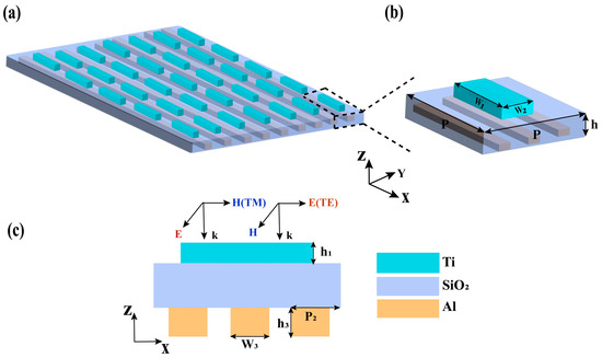
Figure 1.
(a) Schematic illustration of the proposed polarization-sensitive MA consisting of a periodic nanostructured array. (b) The top view of a unit cell of the proposed polarization-sensitive MA; H1, W1, W2, and P1 are the height, length, width, and period of the nanorectangle, respectively. H2 is the thickness of the middle-layer SiO2. (c) The sectional view of a unit cell of the proposed polarization-sensitive MA; W3, H3, and P2 are the width, height, and period of the grating array, respectively.
3. Results and Discussion
The absorption spectra of the proposed polarization-sensitive MA under the incidence of TE- and TM-polarized light are displayed in Figure 2a. It is obviously seen that there is a significant difference in absorption for TE- and TM-polarized light in the wavelength range of 500–2000 nm, with an average absorption of TM- and TE-polarized light of 91.9% and 11.6%, respectively. The greatest absorption difference can reach over 94% in the wavelength range of 1340–1520 nm. For better clarification of the difference in the proposed structure’s absorptive ability for TE- and TM-polarized light, we calculated the extinction ratio (ER) and the results are shown in Figure 2b. The ER is calculated by the following equation:
where and denote the absorption of TM- and TE-polarized light created by the proposed polarization-sensitive MA. The calculated result indicates that the designed polarization-selective MA has a good capacity for absorption differences in TE- and TM-polarized light and the max ER of 14.39 is achieved at the wavelength of 2000 nm.
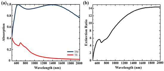
Figure 2.
(a) Absorption spectrum of proposed polarization-sensitive MA under TE- and TM-polarized light. The cyan and red curves are the absorption of TE- and TM-polarized light, respectively. (b) Extinction ratio curves of the proposed polarization-sensitive MA.
To further explore the effects of the bottom Al gratings’ geometric parameter variations on the absorption of the designed polarization-sensitive MA, we simulated the absorption spectra under the illustration of TE- and TM-polarized light, respectively. The calculated results are shown in Figure 3a–d. Figure 3a,b display the absorption performance dependent on the gratings’ width for TM- and TE-polarized light, respectively. In Figure 3a, for TM-polarized light, the absorption of the proposed polarization-sensitive MA increases gradually as the bottom gratings’ width becomes larger at the short wavelengths of 500–630 nm. In the wavelength region of 630–1370 nm, the absorption of the polarization-sensitive MA is almost unchanged with the variations in the bottom gratings’ width. However, for larger wavelength of 1370–2000 nm, the absorption decreases gradually as the width of the bottom Al gratings increases. As for the case of TE-polarized light shown in Figure 3b, when the incident wavelength lies approximately in the range of 500–1500 nm, the absorption of the polarization-sensitive MA increases gradually as the width of the bottom gratings increases. Additionally, approximately from the point of the wavelength of 1300 nm, the absorption of the polarization-sensitive MA remains unchanged while the absorption of the bottom gratings varies. The absorption of the polarization-sensitive MA affected by the height of the bottom Al gratings are exhibited in Figure 3c,d. When the illumination wave source is TM-polarized light, there is no change in the absorption of the polarization-sensitive MA while the height of the bottom gratings varies. For the case of TE-polarized light, the absorption peak has a red-shift with the increased height of the bottom gratings, and the absorption remains almost unchanged from the start of the wavelength of 1250 nm. Namely, there is little variation in the wavelength region of 1250–2000 nm.
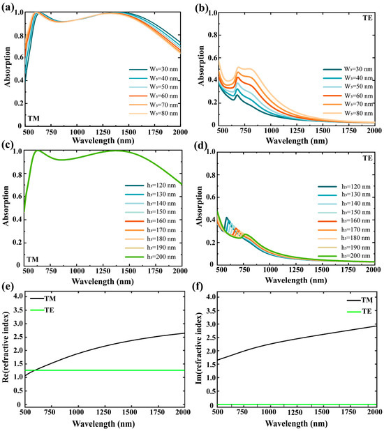
Figure 3.
(a,b) Absorption spectra of different widths of the bottom Al gratings for TM- and TE-polarized light. (c,d) Absorption spectra of different heights of the bottom Al gratings for TM- and TE-polarized light. (e,f) Real and imaginary part of the equivalent refractive index of the bottom Al gratings for TE- and TM-polarized light.
To make clear the principle of the distinction of the absorptive ability for TE- and TM-polarized light, the function of the bottom Al gratings for the two types of polarized light is analyzed firstly. Owing to the oscillating characteristic of free electrons in the metal surface, the linearly polarized light whose electric field vibration direction is parallel to the metallic gratings can excite the electrons to oscillate along the gratings’ direction, resulting in it being reflected back by the metallic gratings. However, on the contrary, due to the limitation of the periodic structure, the linearly polarized light whose electric field vibration direction is perpendicular to the metallic gratings cannot excite free electron oscillation in the metal surface, resulting in it being transmitted directly. Then, based on the equivalent medium theory, the first-order approximations of the equivalent complex refractive index of the sub-wavelength metallic gratings under TE- and TM-polarized light are estimated as follows [28]:
where and represent the real part of the equivalent complex refractive index of the metallic sub-wavelength gratings under TE- and TM-polarized light, respectively. and express the imaginary part of the equivalent complex refractive index of the metallic sub-wavelength gratings under TE- and TM-polarized light, respectively. is the complex refractive index of the metallic grating’s material Al, while is the refractive index of the grating’s groove. Here, the value of equals 1 + i·0, which is that of air. is the duty cycle of the metallic gratings, and here . Figure 3e,f show the results of the equivalent complex refractive index of the metallic gratings under TE- and TM-polarized light. Figure 3e exhibits the real part of the equivalent complex refractive index of the two types of polarized light. In the wavelength range of 500–2000 nm, for TM-polarized light, the real part value changes from 1.1 to 2.6, that of TE-polarized light maintains a value of 1.25. The calculated results of the imaginary part of the equivalent complex refractive index of the two types of polarized light are given in Figure 3f. Across 500–2000 nm, for TM-polarized light, the value of the imaginary part of the equivalent complex refractive index increases gradually from 1.66 to 2.9, while the value always remains at zero under the illustration of TE-polarized light. Therefore, the sub-wavelength metallic gratings exhibit the characteristic of metallic film for TM-polarized light with high reflection, while the characteristic of dielectric film for TE-polarized light is exhibited with high transmission [29].
Next, to reveal the physical mechanism of the huge polarization-sensitive absorptive difference, the electric field distributions at three wavelengths (640 nm, 1530 nm, and 2000 nm) under TM- and TE-polarized light were extracted, respectively, as displayed in Figure 4. Based on the previous analysis, in the wavelength range of 500–2000 nm, the bottom Al gratings for TM-polarized light amount to a high reflective substrate and for TE-polarized light it is approximately equivalent to a high transmissive dielectric film. Therefore, multiple resonance modes will be excited when TM-polarized light is incident onto the proposed structure, which is clearly demonstrated in Figure 4a,c,e. As shown in Figure 4a, a huge localized electric field is located in the cavity formed by the top Ti nanorectangle array, SiO2 spacer, and bottom Al nanogratings, which is caused by the strong F-P cavity resonance. In Figure 4c,e, a huge electric field localization can be observed at the edges of the Ti nanorectangle under the resonance wavelengths of 1530 and 2000 nm, which benefits from LSPR excited at the edges of the Ti nanorectangle [30]. Furthermore, attributed to the high reflective functionality of the bottom Al gratings for TM-polarized light, multiple reflections under a wide-field illumination can occur in the SiO2 spacer, which can increase the probability of energy utilization by prolonging the interaction time between the incident light and structure. It is clearly observed in Figure 4c,e that the localized electric field at the Ti nanorectangle’s edges is strengthened by the enhanced LSPR effect. The aforementioned resonance modes do not occur in the corresponding cases for TE-polarized light, as shown in Figure 4d–f.
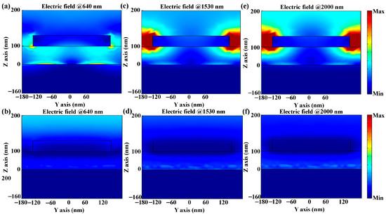
Figure 4.
(a,c,e) Distributions of the electric field (|E|) in the Y-Z plane at the wavelengths of 640, 1530, and 2000 nm under TM-polarized light excitation. (b,d,f) Distributions of the electric field (|E|) in the Y-Z plane at the wavelengths of 640, 1530, and 2000 nm under TE-polarized light excitation.
To analyze the physical mechanism of the huge polarization-sensitive absorptive difference more thoroughly, the distributions of the magnetic field corresponding to the same wavelengths are extracted for TM- and TE-polarized light, respectively, as shown in Figure 5. Figure 5a,c,e represent the distributions of the TM-polarized light magnetic field at 640 nm, 1530 nm, and 2000 nm, respectively, while Figure 5b,d,f correspond to that of the TE-polarized light, respectively. For TM-polarize light, it can be clearly seen that the magnetic field distributions are greatly different from those of the corresponding electric fields. Firstly, from Figure 5a, one can see that the partial magnetic field energy not only distributes at the bottom Al gratings/SiO2 spacer interface but also the air groove, and this resonance mode of localized energy is due to the PSPR mode [31]. Meanwhile, a portion of magnetic energy concentrates at the air/Ti nanorectangle interface and decreases exponentially with the distance from the surface of Ti layer; the same situation occurs in Figure 5c. These energy confinements are attributed to LSPR mode [32]. Secondly, the electric displacement in the middle SiO2 spacer forms a loop, as shown in Figure 5c, which is the typical characteristic of MDR mode [33], meaning that the MDR contributes to enhanced magnetic field localization simultaneously. Furthermore, the F-P cavity resonance mode is obviously observed in Figure 5e, which shows concentrated magnetic field energy in the cavity formed by the Ti nanorectangle array, SiO2 spacer, and bottom Al gratings. In the cavity, the vector of electric displacement is parallel to the direction of the x-axis, which is also the polarization direction of the electric field of incident light. Consequently, the synergistic effect of PSPR, LSPR, F-P cavity resonance, as well as MDR modes lead to a strong localization of magnetic field for TM-polarized light. However, almost no resonance modes were observed in the corresponding cases of TE-polarized light, as shown in Figure 5b,d,f, resulting in a very low absorption. Therefore, the huge difference in absorptive ability for electric and magnetic field energy is the reason that causes the polarization-sensitive characteristics of the designed MA structure.
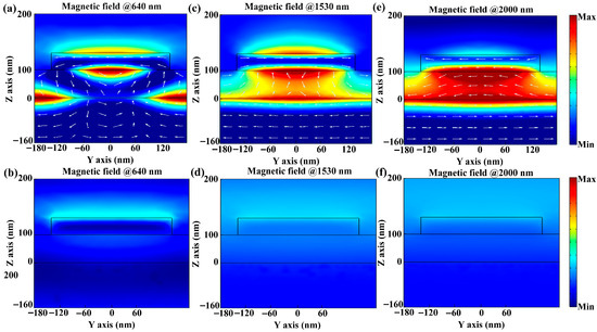
Figure 5.
(a,c,e) Distributions of the magnetic field (|H|) in the Y-Z plane at the wavelengths of 640, 1530, and 2000 nm under TM-polarized light. (b,d,f) Distributions of the magnetic field (|H|) in the Y-Z plane at the wavelengths of 640, 1530, and 2000 nm under TE-polarized light.
To further explore the relationship between the proposed MA’s geometric parameters and its absorption performance, the absorption spectra varying with the parameters (H1, H2, W2, and etc.) for TM- and TE-polarized light are calculated, respectively, as exhibited in Figure 6. Figure 6a is the absorption spectrum of TM-polarized light with the thickness of the SiO2 layer, and it can be seen that the absorption peak moves to longer wavelengths accompanied with an absorption intensity enhancement as the SiO2 layer increases in thickness. The red-shift phenomenon resulted from the wavelength which satisfies the occurrence condition of the F-P cavity resonance and increases with the increasing SiO2 layer thickness. This out-of-plane coupling caused by the F-P cavity of the proposed MA structure is a consequence of the near-field interaction of the nanorectangle and its image in the bottom Al gratings whose function for TM-polarized light is as a metal film [34]. Additionally, the electric field confined in the F-P cavity will be enhanced as the out-of-plane coupling strength in the cavity increases, resulting in an enhanced absorption intensity. Figure 6c displays the absorption spectrum of TM-polarized light dependent on the width of the Ti nanorectangle. We can see that the absorption of the polarization-sensitive MA at longer wavelengths has extremely low intensity at a relatively small filling factor (i.e., a smaller Ti nanorectangle width). As the Ti rectangle’s width increases, the absorption peak positions move to longer wavelengths for the corresponding LSPR mode generated by Ti rectangles, which is enhanced as the Ti width increases, leading to an enhancement of absorption. Figure 6e shows the influence of the top Ti nanorectangle’s thickness on the absorption performance of the proposed MA for TM-polarized light. It can be observed that increasing the Ti nanorectangle’s thickness also can cause a red-shift phenomenon. This is mainly because of the delocalization of charge density at the apex, which increases with the increase in the height [35]. For TE-polarized light, in the whole working region, the absorptive ability is extremely low and almost unchangeable as the geometric parameters of the proposed polarization-sensitive MA vary, as shown in Figure 6b,d,f.
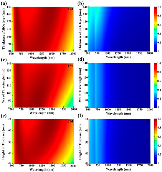
Figure 6.
The absorption performance of the proposed polarization-sensitive MA under TM- and TE-polarized light excitation with various geometric parameters of (a,b) the thickness of SiO2 dielectric layer, (c,d) the width of top Ti square, and (e,f) the height of top Ti nanorectangle. The absorption spectra are simulated under normal incidence.
The absorption characteristic of the proposed polarization-sensitive MA with varying polarization angles of incident light is investigated and shown in Figure 7a. The polarization angle varies from 0° (TE-polarized) to 90° (TE-polarized) insteps of 15°. Under different polarization angles, the absorption spectrum of the proposed polarization-sensitive MA remains a broadband characteristic, but the absorption intensity decreases gradually as the polarization angles increase. To further analyze the polarization characteristic of the proposed polarization-selective MA, we extract the absorption curves of the wavelengths (640 nm, 1530 nm, and 2000 nm) and average absorption as a function of the polarization angle, as shown in Figure 7b. An interesting phenomenon is observed as the relationship between the absorption and polarization angle exhibits a linear-like response. This is due to the linear response of the bottom Al gratings to the polarization angle. The result means that the proposed structure possesses highly polarization-dependent characteristics.
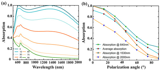
Figure 7.
(a) The broadband absorption spectrum under different polarization angles in steps of 15°. (b) Absorption at different wavelengths and average absorption as a function of polarization angle.
The above discussions are conducted on the basis of normal incidence. However, the tolerance of large oblique incidence angles is a significant performance factor for a polarization-sensitive MA because most light sources exhibit omnidirectional radiation [36]. Therefore, the absorption spectrum of the proposed structure under oblique incidence angles for TM- and TE-polarized light are calculated, respectively, as shown in Figure 8a,b. The incidence angles vary from 0° to 50° in a step of 10°. From Figure 8a, it can be seen that there is no obvious change in whole wavelength region for TM-polarized light, except for a slight fluctuation in the visible and near-infrared ranges when the oblique incident angle is over 30°. This is mainly because the intensity of SPR mode generated by the top Ti nanorectangle fluctuates slightly with wavelengths at large oblique incident angles. For the case of TE-polarized light shown in Figure 8b, there is almost no change in the whole wavelength region. Figure 8c displays the average absorption under different incident angles for TM-polarized light (red curve) and TE-polarized light (blue curve) in the designed wavelength region (500 to 2000 nm). The average absorption difference is 80% across the whole wavelength range. The results reveal that the proposed polarization-sensitive MA exhibits incidence angle-insensitive characteristics and can still work well when the oblique incidence is up to 50°.
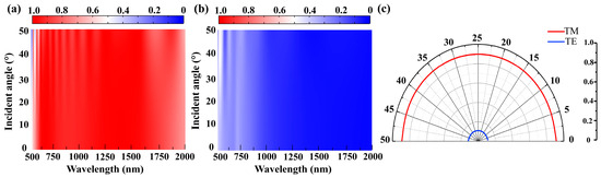
Figure 8.
(a,b) Absorption spectrum as a function of incident angle for TM-polarized light and TE-polarized light. (c) Average absorption as a function of incident angle for TM-polarized light (red curve) and TE-polarized light (blue curve).
To further demonstrate the potential application of the proposed polarization-sensitive MA in polarization detection, a plasmonic photodetector (PD) based on the designed polarization-sensitive MA structure is constructed in simulation and Ge is chosen as the photo-active material. The schematic illustration of the constructed plasmonic PD is depicted in Figure 9a. Here, for simplicity, part of the working wavelength region of 1000–2000 nm is investigated. The thickness of photo-active materials is set as 400 nm and the two types of polarized light (i.e., TM-polarized and TE-polarized light) are used as excitation sources. To explore the performance of the proposed structure in distinguishing the polarization states of light sources, the absorption performance of the plasmonic PD based on the proposed structure for TM- and TE-polarized light in the 1000–2000 nm range is initially calculated and shown in Figure 9b. It can be seen that there is an apparent difference in absorption performance for the two types of polarized light; to illustrate this more intuitively, the distributions of the electric field for TM-polarized and TE-polarized light at 1125 nm and 1550 nm are depicted in insets. The differences in absorption for TE- and TM-polarized light at 1125 nm and 1550 nm are 42.43% and 73.7%, respectively. Furthermore, we calculated the electron concentration in one periodic nanostructure under TE- and TM-polarized light illumination (1550 nm, 40 μW), as shown in Figure 9c. Attributed to the larger absorption difference in the PD for the two types of polarized light, a fairly evident distinction of the electron concentration can be apparently observed. The scale bar in Figure 9c is from 2.6 × 10¹⁵ to 7.8 × 10¹⁵ (unit: 1/cm3). Based on the greater difference in electron concentration, major current density difference values (6.6 × 10⁷ A/m2, 2 V) under the power of 40 μW (1550 nm) can be obtained, as shown in Figure 9d. Furthermore, Figure 9e displays the typical I-V curves of TE- and TM-polarized light under light illumination (1550 nm, 40 μW). On can see that the photocurrent under TM-polarized light excitation is visibly higher than that of TE-polarized light excitation. The different values of the photocurrent can be reached at 11.9 μA under the bias of 2 V. Based on the photocurrents and incident light power, the responsivity of the plasmonic PD can be calculated as follows:
where is the calculated photocurrent, is the dark current, and is the power of illumination light. The calculated as a function of light power under TE- and TM-polarized light is exhibited in Figure 9f. At the bias of 2 V, the maximum difference value of the two types of polarized light is 0.3 A/W.
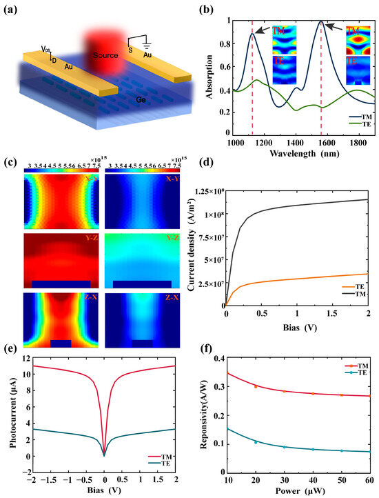
Figure 9.
(a) Schematic of the plasmonic PD functionalized by polarization-sensitive MA structure. (b) Absorption spectra of the plasmonic PD under TE- and TM-polarized light. (c) Electron concentration in one periodic structure under TM-polarized light (left column) and TE-polarized light (right column) excitation. (d) Current density curves of TE-polarized light (yellow line) and TM-polarized (black line) light (1550 nm, 40 μW). (e) I-V curves of TM-polarized light (red line) and TE-polarized light (cyan line) (1550 nm, 40 μW). (f) Responsivity of TE-polarized light (blue line) and TM-polarized light (cyan line) as a function of light power (2 V).
4. Conclusions
In conclusion, using on a bottom layer functionalized metal–dielectric–metal structure, we have designed a polarization-sensitive MA operating in the wavelength range of 500–2000 nm. The proposed polarization-sensitive MA achieves a great absorption difference with an average absorption of 91.9% for TM-polarized light and 11.63% for TE-polarized light in the operating wavelength region of 500–2000 nm. By thoroughly analyzing the metallic/dielectric characteristics of bottom Al gratings for TM- and TE-polarized light as well as the electric and magnetic field distributions at several selected wavelengths, it can be known that the metallic film characteristic of bottom Al gratings cooperated with PSPR, LSPR, F-P cavity resonance, and MDR modes and contribute to a high absorption for TM-polarized light. Furthermore, the dielectric film characteristic of the bottom Al gratings leads to a low absorption of TE-polarized light. The effects of different geometric parameters, polarization angles of incident light, as well as incident angles on the absorption are investigated to acquire the optimal performance of the polarization-sensitive MA. Furthermore, a plasmonic PD functionalized by the proposed polarization-sensitive MA was constructed to explore the potential application of the proposed polarization-sensitive MA in polarization detection. The calculated results demonstrate that the photocurrent difference can reach 11.9 μA under TE- and TM-polarized light at 1550 nm. The features make the proposed polarization-sensitive MA suitable for many applications, including polarization detection and other polarization-sensitive optoelectronic devices.
Supplementary Materials
The following supporting information can be downloaded at: https://www.mdpi.com/article/10.3390/photonics13010006/s1, Figure S1: The refractive index (n, k) curves of metals Al and Ti calculated using the Drude-Lorentz model within the wavelength range of 500–2000 nm; Table S1: Relative parameters of metals Al and Ti.
Author Contributions
Conceptualization, X.W., B.W., and W.W.; methodology, X.W., B.W., and H.L.; software, X.W., S.M., Y.L., and E.H.; validation, X.W. and B.W.; formal analysis, X.W. and B.W.; investigation, X.W., H.L., and B.W.; data curation, X.W. and B.W.; writing—original draft preparation, X.W. and B.W.; writing—review and editing, X.W., J.L., K.Z., Y.J., and S.Y.; visualization, X.W. and Y.L.; supervision, B.W. All authors have read and agreed to the published version of the manuscript.
Funding
This research was funded by the National Natural Science Foundation of China (62104226, 62305339) and Jilin Scientific and Technological Development Program (20230201049GX).
Data Availability Statement
The original contributions presented in this study are included in the article. Further inquiries can be directed to the corresponding author.
Conflicts of Interest
The authors declare no conflicts of interest.
References
- Chen, M.K.; Wu, Y.; Feng, L.; Fan, Q.; Lu, M.; Xu, T.; Tsai, D.P. Principles, functions, and applications of optical meta-lens. Adv. Opt. Mater. 2021, 9, 2001414. [Google Scholar] [CrossRef]
- Shrestha, S.; Overvig, A.C.; Lu, M.; Stein, A.; Yu, N.F. Broadband achromatic dielectric metalenses. Light Sci. Appl. 2018, 7, 85. [Google Scholar] [CrossRef]
- Valentine, J.; Zhang, S.; Zentgraf, T.; Ulin-Avila, E.; Genov, D.A.; Bartal, G.; Zhang, X. Three-dimensional optical metamaterial with a negative refractive index. Nature 2008, 455, 376–379. [Google Scholar] [CrossRef] [PubMed]
- Chiam, S.Y.; Singh, R.; Rockstuhl, C.; Lederer, F.; Zhang, W.L.; Bettiol, A.A. Analogue of electromagnetically induced transparency in a terahertz metamaterial. Phys. Rev. B 2009, 80, 153103. [Google Scholar] [CrossRef]
- Landy, N.I.; Sajuyigbe, S.; Mock, J.J.; Smith, D.R.; Padilla, W.J. Perfect metamaterial absorber. Phys. Rev. Lett. 2008, 100, 207402. [Google Scholar] [CrossRef]
- Chang, C.C.; Kort-Kamp, W.J.M.; Nogan, J.; Luk, T.S.; Azad, A.K.; Tayloe, A.J.; Dalvit, A.A.R.; Sykora, M.; Chen, H.T. High-temperature refractory metasurfaces for solar thermophotovoltaic energy harvesting. Nano Lett. 2018, 18, 7665–7673. [Google Scholar] [CrossRef]
- Mohammadi, E.; Behdad, N. A Wide Dynamic Range Polarization Sensing Long Wave Infrared Detecto. Sci. Rep. 2017, 7, 17475. [Google Scholar] [CrossRef] [PubMed]
- Etezadi, D.; Warner, J.B., IV; Ruggeri, F.S.; Dietler, G.; Lashuel, H.A.; Altug, H. Nanoplasmonic mid-infrared biosensor for in vitro protein secondary structure detection. Light Sci. Appl. 2018, 6, e17029. [Google Scholar] [CrossRef] [PubMed]
- Sun, K.; Riedel, C.A.; Wang, Y.D.; Urbani, A.; Simeoni, M.; Mengali, S.; Zalkovskij, M.; Bilenberg, B.; Groot, C.H.D.; Muskens, O.L. Metasurface optical solar reflectors using AZO transparent conducting oxides for radiative cooling of spacecraft. ACS Photonics 2018, 5, 495–501. [Google Scholar] [CrossRef]
- Bilal, R.M.H.; Muhammad, A.S.; Muhammad, A.N.; Muhammad, Z.; Muhammad, Q.M.; Massoud, Y. Nickel-Based High-Bandwidth Nanostructured Metamaterial Absorber for Visible and Infrared Spectrum. Nanomaterials 2022, 12, 3356. [Google Scholar] [CrossRef]
- Rubin, N.A.; Aversa, G.D.; Chevalier, P.; Shi, Z.J.; Chen, W.T.; Capasso, F. Matrix Fourier optics enables a compact full-Stokes polarization camera. Science 2019, 365, eaax1839. [Google Scholar] [CrossRef] [PubMed]
- Yan, C.; Li, X.; Pu, M.B.; Ma, X.L.; Zhang, F.; Gao, P.; Liu, K.P.; Luo, X.G. Midinfrared real-time polarization imaging with all-dielectric metasurfaces. Appl. Phys. Lett. 2019, 114, 161904. [Google Scholar] [CrossRef]
- Li, W.; Coppens, Z.J.; Besteiro, L.V.; Wang, W.; Govorov, A.O.; Valentine, J. Circularly polarized light detection with hot electrons in chiral plasmonic metamaterials. Nat. Commun. 2015, 6, 8379. [Google Scholar] [CrossRef]
- Wei, J.; Xu, C.; Dong, B.; Qiu, C.W.; Lee, C. Mid-infrared semimetal polarization detectors with configurable polarity transition. Nat. Photonics 2021, 15, 614–621. [Google Scholar] [CrossRef]
- Wu, Y.; Tan, S.J.; Zhao, Y.; Liang, L.; Zhou, M.; Ji, G.B. Broadband multispectral compatible absorbers for radar, infrared and visible stealth application. Prog. Mater. Sci. 2023, 135, 101088. [Google Scholar] [CrossRef]
- Niu, J.H.; Yao, Q.Y.; Mo, W.; Li, C.H.; Zhu, A.J. Switchable bi-functional metamaterial based on vanadium dioxide for broadband absorption and broadband polarization in terahertz band. Opt. Commun. 2023, 527, 128953. [Google Scholar] [CrossRef]
- Wang, X.Y.; Liang, Z.Z.; Yang, F.M.; Shi, X.Y.; Li, J.H.; Dong, Y.J.; Liu, W.Z.; Jia, Y.; Sun, W.W.; Wu, Z.; et al. Chain-type multi-mode polarization-sensitive metamaterial absorber in infrared band. Results Phys. 2025, 68, 108105. [Google Scholar] [CrossRef]
- Chang, F.J.; Wang, Q.; Kuang, K.L.; Peng, W. Polarization-selective dual-band infrared metamaterial perfect absorber. J. Phys. D Appl. Phys. 2024, 58, 035105. [Google Scholar] [CrossRef]
- Hou, E.Z.; Liang, Z.Z.; Shi, X.Y.; Yang, F.M.; Zhang, X.Q.; Dai, R.; Zhang, S.T.; Liu, W.Z.; Jia, Y. Polarization-sensitive metamaterial absorber based on the composite grating structure in the long-wave infrared band. Opt. Laser Technol. 2024, 175, 110676. [Google Scholar] [CrossRef]
- Lei, S.; Huang, R.; Ouyang, M.Z.; Yang, B.W.; Wu, J.S.; Zhong, C.Y.; Fu, Y.G. A polarization-dependent near-infrared metamaterial absorber based on the hybrid halide perovskite in two orthogonal directions. J. Opt. 2023, 25, 105101. [Google Scholar] [CrossRef]
- Shi, X.Y.; Qin, Z.; Zhong, Z.Z.; Meng, D.J.; Jin, J.H.; Zhang, S.T.; Dai, R.; Hou, E.Z.; Xin, W.; Liu, H.; et al. Polarization-selective absorptive and transmissive metamaterials. Opt. Express 2022, 30, 20532–20542. [Google Scholar] [CrossRef]
- Yu, H.H.; Meng, D.J.; Liang, Z.Z.; Xu, H.Y.; Qin, Z.; Su, X.M.; Smith, D.R.; Liu, Y.C. Polarization-dependent broadband absorber based on composite metamaterials in the long-wavelength infrared range. Opt. Express 2021, 29, 36111–36120. [Google Scholar] [CrossRef]
- Qin, Z.; Liang, Z.Z.; Shi, X.Y.; Meng, D.J.; Dai, R.; Sun, C.F.; Xin, W.; Yang, F.M.; Ren, Y.Z.; Feng, J.J. Ultrahigh Extinction Ratio Long-Wave Infrared Polarization-Selective Broadband Metamaterial Absorber. Adv. Photonics Res. 2023, 4, 2200269. [Google Scholar] [CrossRef]
- Du, B.W.; Yang, W.Q.; Jiang, Q.; Shan, H.Y.; Luo, D.Y.; Li, B.W.; Tang, W.C.; Lin, F.; Shen, B.; Gong, Q.H.; et al. Plasmonic-functionalized broadband perovskite photodetector. Adv. Opt. Mater. 2018, 6, 1701271. [Google Scholar] [CrossRef]
- Rakić, A.D.; Djurišić, A.B.; Elazar, J.M.; Majewski, M.L. Optical properties of metallic films for vertical-cavity optoelectronic devices. Appl. Opt. 1998, 37, 5271–5283. [Google Scholar] [CrossRef]
- Chen, H.T.; Taylor, A.J.; Yu, N.F. A review of metasurfaces: Physics and applications. Rep. Prog. Phys. 2016, 79, 076401. [Google Scholar] [CrossRef]
- Yu, P.; Besteiro, L.V.; Huang, Y.; Wu, J.; Fu, L.; Tan, H.H.; Jagadish, C.; Wiederrecht, G.P.; Govorov, A.O.; Wang, Z. Broadband Metamaterial Absorbers. Adv. Opt. Mater. 2019, 7, 1800995. [Google Scholar] [CrossRef]
- Brundrett, D.L.; Glytsis, E.N.; Gaylord, T.K. Homogeneous layer models for high-spatial-frequency dielectric surface-relief gratings: Conical diffraction and antireflection designs. Appl. Opt. 1994, 33, 2695–2706. [Google Scholar] [CrossRef] [PubMed]
- Chang-Hasnain, C.J.; Yang, W.J. High-contrast gratings for integrated optoelectronics. Adv. Opt. Photon. 2012, 4, 379–440. [Google Scholar] [CrossRef]
- Mayer, K.M.; Hafner, J.H. Localized surface plasmon resonance sensors. Chem. Rev. 2011, 111, 3828–3857. [Google Scholar] [CrossRef]
- Cong, J.W.; Zhou, Z.Q.; Yun, B.F.; Lv, L.; Yao, H.B.; Fu, Y.H.; Ren, N.F. Broadband visible-light absorber via hybridization of propagating surface plasmon. Opt. Lett. 2016, 41, 1965–1968. [Google Scholar] [CrossRef] [PubMed]
- Zhou, Y.; Qin, Z.; Liang, Z.Z.; Meng, D.J.; Xu, H.Y.; Smith, D.R.; Liu, Y.C. Ultra- broadband metamaterial absorbers from long to very long infrared regime. Light Sci. Appl. 2021, 10, 138. [Google Scholar] [CrossRef]
- Zhang, Z.J.; Yu, Z.Y.; Liang, Y.Z.; Xu, T. Dual-band nearly perfect absorber at visible frequencies. Opt. Mater. Express 2018, 8, 463–468. [Google Scholar] [CrossRef]
- Nordlander, P.; Prodan, E. Plasmon hybridization in nanoparticles near metallic surfaces. Nano Lett. 2004, 4, 2209–2213. [Google Scholar] [CrossRef]
- Lee, E.K.; Song, J.K.; Jeong, K.Y. Design of plasmonic nanoantenna for total internal reflection fluorescence microscopy. Opt. Express 2013, 21, 23036. [Google Scholar] [CrossRef]
- Li, H.Y.; Chen, C.; Qiu, X.Y.; Zhou, S.Y.; Liu, M.X.; Li, C.; Zhang, H.; Zhang, Z. Template-Made Ultrahigh, Broadband, and Omnidirectional Light Absorption Surface for Enhanced Solar Energy Harvesting and Utilization. Adv. Funct. Mater. 2024, 44, 2407135. [Google Scholar] [CrossRef]


Disclaimer/Publisher’s Note: The statements, opinions and data contained in all publications are solely those of the individual author(s) and contributor(s) and not of MDPI and/or the editor(s). MDPI and/or the editor(s) disclaim responsibility for any injury to people or property resulting from any ideas, methods, instructions or products referred to in the content. |
© 2025 by the authors. Licensee MDPI, Basel, Switzerland. This article is an open access article distributed under the terms and conditions of the Creative Commons Attribution (CC BY) license.