Abstract
We present a differentiable, curriculum-based optimization workflow for the engineering-oriented design of large-aperture reflective optical systems. The method integrates physics-informed differentiable ray tracing with a progressive, two-stage optimization strategy that evolves from simple Ritchey–Chrétien (RC) foundations to complex four-mirror architectures. Without relying on pretrained models or large datasets, the workflow optimizes geometric and physical parameters under field-weighted RMS, focal length, and dynamic obscuration constraints while maintaining minimal perturbation to primary and secondary mirrors. Validated through Zemax-based analysis, the optimized systems achieve high imaging quality with improved RMS uniformity and stable convergence across varying aperture scales. This approach provides a practical and scalable pathway for the design and optimization of reflective optical instruments, offering strong robustness and adaptability for diverse imaging applications.
1. Introduction
The automated design of imaging optical systems remains a fundamental challenge in modern optics. This study focuses on automatic design of high-resolution reflective optical systems for space applications, aiming to establish an efficient and fully differentiable optimization framework. Traditionally, the design of space-based reflective telescopes has relied on third-order aberration theory and classical analytical design methods, which provide analytical relations between system parameters and aberration coefficients to determine initial configurations [1,2]. However, as the number of reflective surfaces increases and imaging requirements become more stringent, classical analytical or iterative approaches become insufficient. Although commercial tools such as Zemax and Code V are able to converge for many conventional design tasks, their damped least-squares–based optimization often tends to be trapped in local minima, particularly in highly coupled multi-mirror systems. Escaping such local minima typically requires extensive manual tuning or very long optimization cycles, sometimes lasting many hours.
Recently, deep learning has been increasingly adopted in optical design and computational imaging, driving AI-based progress in diffractive optics, optical neural networks [3,4,5,6,7,8,9,10], freeform surface design [11,12,13], and end-to-end optimization [14,15,16,17,18,19,20,21,22,23]. These approaches can be broadly categorized into two paradigms. The first employs supervised deep neural networks that map system-level parameters to predicted optical designs, enabling the rapid generation of initial configurations once trained. Although efficient, this paradigm requires large, high-quality datasets and often suffers from limited generalization. The second paradigm adopts physics-informed differentiable optimization, where the system evolves from simplified structures to full complexity under domain-specific regularizations. Although these methods are less general, they are particularly well suited to highly complex or data-scarce design tasks and often outperform in specific scenarios.
In the first paradigm, Côté et al. [24] proposed an automatic pipeline to generate separated doublet lenses, establishing the basis for data-driven refractive design. They later trained deep neural networks using 13 samples from the Zebase6 database [25], achieving designs that resemble classical performance [26]. Follow-up research has focused on improving network architectures, including replacing fully connected (FC) layers with recurrent neural networks (RNNs) [27,28], extended models to multi-surface freeform systems [12,29], and introduced vignetting modeling and dynamic aiming for better aperture control [30,31,32,33]. Later studies integrated microscope datasets [34,35,36] and Transformer-based encoders [37], enabling generative modeling for high-performance microscopy [38]. Frameworks such as FreeformNet [39] and DLOD [40] further enhanced design diversity and speed, allowing neural networks to generate hundreds of high-quality optical structures per second.
In the second paradigm, differentiable frameworks such as DiffOptics [41,42,43] leverage gradient backpropagation through ray–surface interactions, substantially reducing the computational load of large-scale ray tracing. Building on this foundation, the DeepLens framework [44] introduced curriculum learning and regularization-based control to progressively enlarge the entrance pupil aperture, achieving refractive designs from randomly initialized surfaces that rival classical performance. However, high-resolution space-based reflective telescopes present unique challenges: the scarcity of reference designs limits data-driven approaches, making curriculum-learning-based differentiable optimization particularly suitable for this domain.
In this work, we focus on the automatic design of large-aperture, high-resolution reflective telescopes for Earth observation, which demand compact structure and robustness to mechanical and thermal perturbations. Following the curriculum-learning-based paradigm, we develop a differentiable optimization framework customized for reflective architectures. Starting from an optimized foundation for the Ritchey–Chrétien (RC) system, we extend the methodology to four-mirror configurations and establish a two-stage optimization framework. Compared to existing transmissive frameworks such as DeepLens, our method introduces restructured ray-tracing logic, a robust RMS-based image quality estimator, physics-informed regularization terms, and high-precision solvers tailored for reflective geometries.
The main contributions of this paper are summarized as follows:
- 1.
- We propose a differentiable ray-tracing framework tailored for large-aperture coaxial reflective systems, and establish an RC-based optimization foundation that serves as a reusable front-end module for extending to more complex multi-mirror architectures (e.g., four-mirror systems). The proposed framework incorporates axial sag correction and supports flexible control over central obscuration and field-of-view weighting.
- 2.
- We present a two-stage optimization strategy for four-mirror systems, using the RC focal point as an intermediate relay. This decouples the optimization of the primary–secondary mirror pair from the remaining mirrors, thereby improving convergence stability. Moreover, we incorporate several physics-informed regularization terms, such as focal length constraints, ray source propagation control, and cone angle matching, to enable efficient automatic generation of complex designs without relying on large-scale training datasets.
- 3.
- We validate the proposed optimization framework through Zemax-based optical analysis, demonstrating superior optical performance compared to traditional methods. The final designs exhibit strong practical potential for deployment in high-resolution reflective space telescopes.
2. Methods
As shown in Figure 1, the optimization begins with a selected small-aperture foundation (e.g., an RC-type structure) and gradually expands the field of view and aperture through a curriculum-inspired schedule. During each stage, differentiable ray tracing is performed to compute field-dependent RMS losses and regularization terms, which are propagated backward to update the optical parameters of the mirrors and inter-element distances. The framework incorporates a two-stage joint optimization strategy and RMS based performance constraints, balancing the accuracy of the focal length, control of the mirror sag (keeping the axial sag within a physically reasonable range during optimization), and overall imaging quality. This design allows the system to efficiently converge toward high-resolution large-aperture configurations while maintaining physical interpretability and numerical stability.
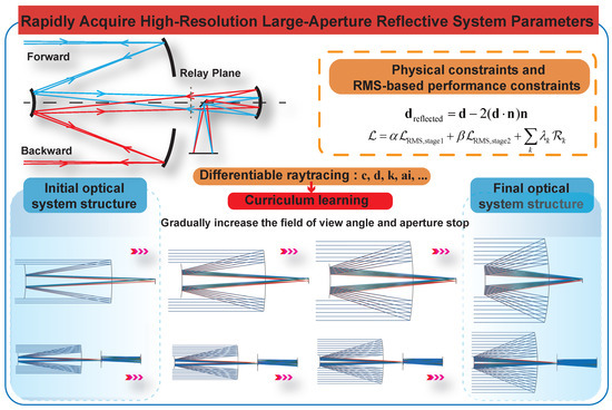
Figure 1.
Overall workflow of the proposed differentiable optimization framework for reflective space telescopes. The workflow integrates a two-stage joint optimization strategy with RMS-based performance constraints, guided by differentiable ray tracing and gradient backpropagation. Starting from a small-aperture initial foundation, the system progressively increases the field of view and aperture stop, achieving high-resolution large-aperture designs with stable convergence and physics-consistent parameter updates.
2.1. Construction of a Differentiable Optimization Workflow for Space-Based Reflective Telescopes
In the automated design of large-aperture space telescopes, traditional optical optimization software typically relies on finite-difference or numerical optimizers, which struggle to balance efficiency with high-precision gradient estimation. To address this limitation, we propose a differentiable geometric ray-tracing model specifically designed for coaxial reflective systems. The proposed model substantially improves both robustness and structural compatibility, making it particularly suitable for deep-learning-driven structural optimization.
2.1.1. Differentiable Modeling of Optical Parameters
The design variables—mirror curvature c, axial position d, conic constant k, and high-order aspheric coefficients —are collectively represented by a parameter vector . For each sampled ray i, the intersection on the image plane is denoted as , where denotes the ray-tracing function under parameter . The imaging accuracy is quantified by the mean squared deviation between the predicted and target spots:
During optimization, gradients are automatically computed via the chain rule and used for parameter updates through the Adam optimizer:
where is the learning rate.
2.1.2. Aspheric Surface Representation and Reflection Modeling
Each reflective surface is described by an even-order asphere:
where denotes the radial coordinate. The reflected direction follows the law , with the unit surface normal.
Ray–surface intersections are solved by Newton iterations with adaptive step control to prevent overshooting, compared with transmissive models, reflective tracing requires tighter stability control due to multiple reflections and high curvature, we adopt dynamic step clamping and convergence thresholds to ensure differentiability and robust convergence under large-aperture conditions [41,42,43].
2.1.3. Structural Considerations for Reflective Systems
Unlike transmissive systems (e.g., DeepLens), where a forward-propagated ray almost always encounters the next refractive surface, multi-mirror reflective systems are highly sensitive to the local surface normals and the relative placement of the mirrors. During early iterations, when the curvatures and axial positions are still far from a physically meaningful configuration, a reflected ray may propagate in a direction where no subsequent mirror is reachable. As illustrated in Figure 2a, such a ray never encounters the next surface in the optical system, and therefore no valid intersection can be computed. In this sense, the optical path is said to be non-connected. In contrast, Figure 2b shows that in a transmissive system a forward-traced ray typically continues to intersect each surface in sequence, even when the lenses are not yet well optimized. This inherent geometric continuity greatly simplifies early-stage optimization. Reflective systems do not share this property because each interaction changes the direction of the ray according to the mirror normal.
To ensure that meaningful optimization can begin, we first construct an optimization foundation whose geometry guaranties full optical path connectivity. In this baseline configuration, rays launched from the detector edge can sequentially reach all preceding mirrors, and forward-propagated parallel rays can reflect through the entire system and arrive at the detector plane. This guaranties that every mirror provides valid intersection points in the early iterations, enabling the computation of key system parameters such as focal length, field angle, and F-number. Without such an optimization foundation, a reflective system initialized from flat or weakly curved surfaces would fail to produce connected ray paths, making it impossible to evaluate the system or drive the optimization process.

Figure 2.
Illustration of the differences between large-aperture reflective systems and small-aperture transmissive systems under curriculum-based optimization. (a) Optical path connectivity in a reflective multi-mirror system: early iterations may lose connectivity when rays fail to reach the next mirror due to unfavorable surface normals. (b) Optical path connectivity in a transmissive system: forward-propagated rays naturally maintain sequential intersections with each surface, even when the lenses are not yet well optimized. (c) Illustration of geometrically invalid marginal rays caused by an insufficient initial propagation distance in reflective systems, a phenomenon that does not occur in transmissive designs. (d) Importance of sag correction: inaccurate sag estimation affects the axial distance between surfaces, leading to errors in focal length and field angle computation.

In addition, we introduce an initial propagation distance between the parallel light emitting plane and the primary mirror, as illustrated in Figure 2c. The initial propagation distance is chosen such that:
where is the surface sag and R represents the aperture radius of the mirror. This ensures that the emitting plane lies completely in front of the sagged mirror surface, so that all sampled rays originate in free space and can reach the mirror without starting inside the mirror volume. In practice, this prevents marginal rays from becoming invalid due to geometric overlap between the source plane and the mirror profile when the aperture and sag are large. The value of is chosen consistently with the aperture size, which keeps the valid-ray ratio high throughout curriculum learning while leaving the intersection direction controlled by the usual condition along the current propagation direction.
Moreover, in a reflective multi-mirror system the axial spacing between surfaces must account for the local sag of each mirror. As illustrated in Figure 2d, the edge point of a mirror may deviate significantly from its vertex plane, especially in large-aperture configurations. If rays were propagated using only the nominal axial distance d between surfaces, the resulting geometric relationships would no longer match the actual mirror geometry, leading to errors in estimating focal length, field angles, and surface intersection points. To avoid this discrepancy, we apply a sag-correction step before computing the next ray origin. For a mirror with aperture radius R, we evaluate its edge sag and adjust the effective surface position accordingly. For example, the axial location of the last aperture surface is updated using:
so that rays are propagated from the physically accurate surface boundary rather than from the nominal vertex plane. This refinement is applied at every iteration, ensuring that the evolving surface shapes remain geometrically consistent with ray tracing and preserving stable optical connectivity throughout the optimization process.
Taken together, these modifications collectively ensure that the reflective optimization framework remains numerically stable, fully differentiable, and compatible with gradient-based training under large-aperture conditions.
2.1.4. Ray Obscuration Control and Dynamic Optical Region Determination
In reflective systems with central obscuration, the effective optical regions on the mirrors may evolve as the entrance aperture is gradually expanded during curriculum learning. To ensure consistent ray validity and stable optimization, our framework updates the usable optical regions dynamically at each iteration.
Specifically, two types of rays are employed. Backward-propagated rays are launched from the detector edge toward the mirror system to calculate system parameters such as field of view and focal length. A ray is treated as valid only if it successfully reaches all reflective surfaces and exits through the primary mirror; otherwise, it is discarded by assigning zero weight. This process implicitly determines the active optical regions on each mirror at the current iteration.
Meanwhile, forward-propagated parallel rays are used for RMS and geometric spot evaluation. Rays whose initial coordinates fall within the obscured region defined by the current secondary mirror geometry are excluded prior to tracing. As the primary aperture expands, the obscuration radius is updated consistently, allowing the valid optical region to grow smoothly without introducing abrupt changes in ray availability.
2.2. A Two-Stage Optimization Workflow Based on System Decomposition
To enhance the stability and feasibility of optimizing large-aperture, high-resolution reflective systems, we propose a physically informed two-stage optimization framework that decomposes the full four-mirror telescope into modular subsystems. The framework adopts the Ritchey–Chrétien (RC) configuration as the initial optimization foundation and extends it into a four-mirror system. Using on-axis () geometric relations, the system is divided along the physical propagation path into two subsystems (Figure 3):
The front subsystem comprising the primary and secondary mirror, and the rear subsystem consisting of the tertiary mirror, quaternary mirror, and a flat folding mirror (fm1). This decomposition leverages the fact that a Ritchey–Chrétien (RC) system forms a well-defined intermediate focal plane behind the primary mirror. The primary–secondary mirror pair therefore constitutes a complete front optical subsystem with a physically meaningful intermediate image plane, while the remaining mirrors form a rear subsystem that reimages this intermediate focus onto the detector.

Figure 3.
(a) Three-dimensional schematic of the proposed high-resolution reflective optical system with off-axis correction. (b,c) illustrate the front and rear subsystems, respectively, obtained by removing the off-axis tilt and decomposing the on-axis () field geometry.
Figure 3.
(a) Three-dimensional schematic of the proposed high-resolution reflective optical system with off-axis correction. (b,c) illustrate the front and rear subsystems, respectively, obtained by removing the off-axis tilt and decomposing the on-axis () field geometry.

The overall two-stage optimization proceeds as follows:
- 1.
- Stage 1—RC Focusing: Parallel rays enter through the primary mirror, reflect off the secondary, and converge at the intermediate RC focal plane. The RMS spot radius and divergence angle are evaluated at this focal point.
- 2.
- Stage 2—Rear-System Reimaging: The RC focus is treated as a virtual point source that emits rays in a conical pattern with divergence angle . Rays propagate through the tertiary, folding, and quaternary mirrors to the final image plane.
- 3.
- Joint Objective: RMS spot radius is minimized simultaneously in both stages. Rear-system parameters remain differentiable and are updated together with front-system parameters, thereby achieving a coordinated optimization of angular geometry, structural configuration, and image quality.
Although the intermediate RC focal plane could, in principle, be sampled directly by tracing the rays that physically emerge from the primary–secondary pair, we found that using these rays as the illumination for Stage 2 introduces two major difficulties in large-aperture reflective systems. First, the RC focal spot may temporarily broaden during the early iterations of optimization, and this perturbation propagates into the rear subsystem, causing the intermediate focal plane to drift toward the detector. Such drift weakens the structural advantage of the natural configuration and destabilizes the global geometry. Second, the angular distribution of rays transmitted through the RC pair is strongly shaped by the central obscuration and local aspheric curvature. As a result, the ray bundle arriving at the RC focal plane exhibits irregular and incomplete sampling of field angles, which reduces the quality of the learning signal for the rear subsystem and significantly slows convergence.
Treating the RC focal plane as a virtual source avoids these difficulties by providing a clean and stable conical ray bundle whose divergence satisfies , independent of temporary aberrations in the RC subsystem. This ensures that the rear subsystem receives a well-conditioned and physically consistent input at every iteration, supporting reliable optimization of the full system.
In addition, evaluating RMS divergence at two planes—the RC focal plane and the final image plane—naturally decouples the optimization roles of the front and rear subsystems. The primary–secondary mirrors are guided to form a stable intermediate image by minimizing the RMS at the RC plane, while the rear mirrors independently reimage this intermediate focus onto the detector by minimizing the RMS at the sensor plane. A single sensor-plane metric cannot provide this separation, because it forces both subsystems to compensate for each other’s evolving aberrations within a shared objective. The proposed method preserves structural consistency and leads to more stable and efficient optimization for large-aperture reflective systems.
Angular Consistency Constraint
We define the RC system’s intermediate focus as the transition point between stages. The effective angular divergence is obtained via forward ray tracing and defined as:
where is the maximum effective off-axis ray height at the secondary mirror edge, and L is the axial distance from that point to the intermediate focus. To ensure geometric continuity, the rear subsystem reconstructs an identical emission cone .
The RMS radius of the RC focal spot on evaluation surface 1 is defined as
where denotes the ith ray intersection on the focal plane and is the centroid of all valid intersections.
The rear subsystem uses a sampling function to generate emission rays that preserve both spatial extent and angular divergence of the RC focus. Stage 1 and Stage 2 correspond to the tasks of initial focusing and reimaging shaping, respectively. By introducing a well-defined intermediate focal constraint, the system design is divided structurally while decoupling optical functions. This strategy improves optimization stability and precision, and allows straightforward extension to three- or five-mirror systems.
2.3. Automated Curriculum Learning Optimization Process
In high degree of freedom reflective space telescope systems, direct optimization over the full aperture and wide field of view is highly challenging. Common issues include ray-tracing failures, unstable gradients, and slow convergence, especially when mirror shapes and relative positions are optimized simultaneously. To overcome these difficulties and enhance both stability and physical plausibility, this study adopts the concept of curriculum learning and develops a progressive, staged optimization pipeline. This strategy aims to construct reflective optical systems with favorable initial imaging performance in a stable and physically grounded manner.
Curriculum learning, proposed by Yoshua Bengio and collaborators [45,46,47], emphasizes training models in a progression from easier to more complex tasks, thereby accelerating convergence and improving generalization. Xinge Yang et al. [44] introduced this concept into deep-learning-based refractive optical system design (DeepLens), demonstrating its effectiveness in handling complex structural configurations. Building on this foundation, we extend the curriculum learning framework to reflective systems, introducing structural modifications to support occlusion control and effective pupil extraction. These enhancements enable automatic optimization of high-resolution space-based reflective systems.
In our implementation, the optimization schedule is parameterized by the normalized primary mirror aperture ratio , where denotes the final designed radius of the primary mirror. Optimization begins with a smaller effective aperture (e.g., ), where ray tracing is more reliable and on-axis imaging is inherently stable. As optimization progresses, is progressively increased according to a monotonic schedule:
where controls the expansion rate of the optimization region. At each stage, system variables such as focal length, field-of-view range, and mirror spacing are adaptively reweighted to preserve physical continuity and gradient smoothness. This staged evolution allows the system to gradually explore peripheral imaging regions, enhancing both optical design flexibility and global convergence stability.
By coupling differentiable ray tracing with curriculum-based scheduling, the framework achieves stable and interpretable optimization of complex multi-mirror reflective systems without requiring large-scale datasets or pre-trained neural models.
2.4. Composite Loss Functions for Unsupervised Optimization of Reflective Optical Systems
To achieve fully unsupervised optimization of large-aperture reflective telescopes, we construct a compact composite loss that unifies multiple optical performance metrics and physical regularizations. Unlike supervised designs, this formulation directly evaluates system geometry through differentiable ray tracing, and performs gradient-based updates via PyTorch’s (v2.1.0) automatic differentiation engine [48].
Reflective architectures differ from transmissive systems in several aspects: they are inherently achromatic and free from self-intersection artifacts due to large inter-mirror spacing. Thus, we exclude chromatic and overlap-related penalties, placing emphasis on (1) image quality across multiple fields, (2) stage-wise convergence between the RC and reimaging subsystems, and (3) manufacturability and focal constraints.
The total loss function is expressed as:
where denotes additional regularization terms such as surface-shape constraints, focal-length penalties, and stability control. All components are differentiable, enabling smooth gradient propagation through complex multi-reflection paths.
The formulae for the various loss constraints are defined as follows:
Here, penalizes deviation from the desired focal length, and limits excessive sag deformation for manufacturability. A small baseline focusing constraint is further included to maintain on-axis image sharpness and prevent gradient stagnation during early iterations. This unified formulation maintain numerical stability, physical consistency, and interpretability of the optimization process.
3. Results and Discussion
3.1. Selection of Optimization Foundations and Key Validation Strategies
The initial two-mirror Ritchey–Chrétien (RC) configuration employed in this study originates from the N_014 model in the Zebase6 optical database. It consists of two even aspheric reflective mirrors, with primary and secondary apertures of 200 mm and 60 mm, respectively, a half field of view (FOV) of 0.3∘, and a focal length of 801.0 mm. Based on this RC optimization foundation, we further increased system complexity by constructing an optimization foundation for a four-mirror (4M) reflective system with a primary mirror aperture of 2200 mm, a half FOV of 0.2∘, and a focal length of 33,333.33 mm. Compared with the RC baseline, the 4M system possesses an order-of-magnitude larger aperture and focal length, representing a typical high-resolution space telescope configuration.
Figure 4 shows the geometric layouts and spot diagrams of the two optimization foundations, generated by our in-house differentiable ray-tracing engine. A flexible obscuration-control module is embedded between the primary and secondary mirrors, allowing dynamic adjustment of the central obscuration ratio during optimization. This mechanism maintains a sufficient proportion of valid rays while improving overall imaging stability and physical fidelity.
- Key validation measures. Reflective systems with large apertures amplify ray-tracing sensitivity to initial geometry. To improve valid ray ratios and the robustness of the ray-tracing process, two key strategies were introduced: (1) sag correction, which refines the numerical representation of surface sag to improve ray–surface intersection accuracy and enhance the overall computational precision during optimization, and (2) adjustment of the initial propagation distance , defined as the axial distance from the parallel light source to the aperture plane of primary mirror. This distance directly affects the angular spread and obscuration of incident rays, thereby influencing the valid-ray ratio and focusing accuracy.
To verify the necessity and effectiveness of these two key measures, we conducted a systematic comparative analysis under different initial propagation distances and sag correction conditions. As shown in Figure 5, increasing leads to a rapid rise in the valid ray ratio, which stabilizes as the value approaches the maximum sag of the primary mirror. Further tests confirm that an initial that is too small or too large results in a drop in the valid ray ratio to near zero, rendering reliable ray tracing impossible. Therefore, in practical optimization processes, it is advisable to set to a value greater than the maximum sag of the primary mirror or close to its aperture size. This configuration prevents rays from directly striking the mirror edge during early iterations, which could otherwise render them invalid.
It is worth noting that for more complex multi-mirror systems (such as the four-mirror system), the valid ray ratio may still be constrained to a 60–70% range due to inherent structural occlusions, even after stabilization. Nevertheless, this does not compromise the reliability of optical performance evaluation, as the primary focus during ray-based optimization remains on focal length accuracy and image quality, both of which can still meet engineering requirements. As propagation distance increases, the focal length rapidly converges toward the reference value. After enabling sag correction, the oscillation of the focal length curve is reduced. The resulting curve aligns more closely with the reference, confirming the critical role of sag correction in large-aperture systems.

Figure 4.
(a,c) Show the geometric layout and spot diagrams of the RC optimization foundation; (b,d) correspond to the four-mirror system. The spot diagrams intuitively illustrate the focusing performance and spot distributions under different fields of view, verifying the effectiveness and necessity of obstruction modeling and multi-field sampling strategies in optimizing complex structures.


Figure 5.
Variation in valid ray ratio with respect to initial propagation distance for both (a) the RC optical configuration and (b) the four-mirror (4M) system. (c) Focal length variation of the four-mirror (4M) system under different initial propagation distances.
Figure 5.
Variation in valid ray ratio with respect to initial propagation distance for both (a) the RC optical configuration and (b) the four-mirror (4M) system. (c) Focal length variation of the four-mirror (4M) system under different initial propagation distances.

3.2. Performance Validation of the RC Two-Mirror Reflective System
We first evaluate the proposed optimization framework on a classical Ritchey–Chrétien (RC) two-mirror reflective system. Due to its compact structure and strong axial symmetry, the RC configuration serves as a representative and transferable frontend module for more complex multi-mirror systems.
Following the parameter configuration in Section 3.1, an optimization scenario is designed to examine the adaptability of the framework to different focal-length and field-of-view (FOV) requirements, as well as its robustness against initial perturbations.
- Target 1—Shortened focal length with extended FOV. In this experiment, the focal length is reduced from 801.0 mm to 700.0 mm, and the total FOV is increased from 0.6∘ to 0.8∘. Despite the broader field and shorter focal length, the optimization follows a similar convergence pattern (Figure 6), where the RMS value initially rises due to structural reconfiguration but later stabilizes under field-aware regulation. The final spot diagrams confirm balanced imaging across the field. Parameter comparison in Table 1 again reveals minor changes in the primary mirror and major shape adaptation of the secondary mirror, highlighting that the optimization algorithm maintains controllability under diverse design targets.
 Table 1. Comparison of RC mirror parameters before and after optimization for Target 1. M0 and M1 denote the primary and secondary mirrors, respectively.

Figure 6.
Optimization results under Target 1: (a) Optimized geometry; (b) multi-field spot diagrams after optimization; (c) convergence of the composite objective value; (d) RMS evolution during optimization. Despite the shortened focal length and extended FOV, the optimization exhibits an initial increase in RMS caused by structural reconfiguration, followed by stable oscillatory convergence under field-aware regulation.

- Robustness to initial perturbations. To further assess tolerance to model bias, the secondary mirror curvature in the RC foundation was deliberately perturbed, and the Target 1 optimization was re-executed under this degraded initial condition. As shown in Figure 7, the optimization converges reliably even when substantial initial errors are introduced. This experiment demonstrates that the proposed differentiable optimization framework exhibits strong robustness, high adaptability, and effective self-correction capability during training.

Figure 7.
(a,c) Show the optical layout and spot diagrams under perturbed initial conditions; (b,d) illustrate the results after re-optimization. Despite substantial initial shape errors, the proposed automated optimization framework achieves stable convergence and significant improvements in image quality, demonstrating strong tolerance to initial errors and high adaptability.

3.3. Automatic Optimization Results for the Four-Mirror System Based on the Two-Stage Optimization Workflow
Based on the original off-axis four-mirror (4M) optical system, our optimization process first eliminates the off-axis compensation and fully leverages the geometric relations under the zero-field condition. Furthermore, a two-stage segmented optimization framework is introduced. This strategy enables faster extraction of key optimized parameters without being disturbed by other variables.
Compared to the RC optical system, the 4M system has higher structural complexity and thus requires more precise regulation to avoid structural collapse. As the primary optimization objective, the focal length plays a crucial role in guiding convergence. During the iterative process, the relative weight of the focal length loss is gradually reduced. To further refine the optimization results, we automatically adjust the relative weights of the focal length and RMS at the 50% iteration step, resulting in the distinct changes observed in Figure 8.

Figure 8.
Overview of the optimization process for the four-mirror (4M) optical system. (a) Optimized geometry; (b) convergence of the composite objective value; (c) RMS evolution during optimization; (d) multi-field spot diagrams after optimization. A scheduled weight update at 50% of the iteration steps leads to the observable change of convergence behavior and accelerates the approach to the final design target.

Table 2.
Comparison of four-mirror (4M) system parameters before and after optimization for Target 2. M0, M1, M2, and M4 correspond to the primary, secondary, tertiary, and quaternary mirrors. M3 is a flat folding mirror whose parameters remain fixed and are therefore not listed.
Table 2.
Comparison of four-mirror (4M) system parameters before and after optimization for Target 2. M0, M1, M2, and M4 correspond to the primary, secondary, tertiary, and quaternary mirrors. M3 is a flat folding mirror whose parameters remain fixed and are therefore not listed.
| Quantity | Surface | Initial | Optimized | Change |
|---|---|---|---|---|
| (mm) | M0 (primary) | −5707.803 | −5707.803 | +0.0% |
| M1 (secondary) | −1309.501 | −1313.682 | −0.3% | |
| M2 (tertiary) | −2314.688 | −2377.229 | −2.7% | |
| M4 (quaternary) | −6310.201 | −5965.302 | +5.5% | |
| Distance d (mm) | M0 (primary) | 0.000 | 0.000 | +0.0% |
| M1 (secondary) | −2315.462 | −2315.462 | +0.0% | |
| M2 (tertiary) | 2174.375 | 2174.375 | +0.0% | |
| M4 (quaternary) | 2174.375 | 2163.241 | −0.5% | |
| Conic k | M0 (primary) | −1.000 | −1.000 | +0.0% |
| M1 (secondary) | −2.051 | −2.074 | −1.1% | |
| M2 (tertiary) | −0.587 | −0.629 | −7.3% | |
| M4 (quaternary) | −23.697 | −23.704 | +0.0% |
As seen in Table 2, variations in the system parameter generally follow the principle of minimal modification. The main adjustments are concentrated on the tertiary and quaternary mirrors, while the primary and secondary mirrors remain largely stable. This behavior aligns with the engineering requirements of large-aperture systems, where maintaining the relative stability of the primary and secondary mirrors is critical for rapid adaptation and fine-tuning of subsequent optical performance.
3.4. Independent Optical Validation and Comparison Using Zemax
To further validate the effectiveness of the proposed two-stage optimization framework, an independent optical validation and comparison was performed using the commercial optical design software Zemax OpticStudio (v20.3.2). Under identical initial configurations and optimization targets (Target 2, where f is reduced from 33,333.3 to 31,000.0 ), the built-in Zemax damped least-squares (DLS) optimizer was executed with equivalent variable constraints and merit-function weights. The results were then directly compared with those produced by our differentiable optimization pipeline (Figure 9).

Figure 9.
Comparison between the proposed optimization framework and Zemax under identical Target 2 conditions. (a,c,e) show the optical layout, MTF curves, and wavefront error (WFE) map obtained using Zemax. (b,d,f) present the corresponding results produced by the proposed method. The proposed method achieves smoother MTF responses and reduced peak WFE, demonstrating improved convergence stability and enhanced aberration-correction capability.

The comparison demonstrates that the proposed framework achieves comparable or superior performance relative to Zemax in both image quality and convergence efficiency, effectively overcoming the limitations of traditional local optima while significantly improving image quality and overall convergence speed. This validates the applicability and robustness of our two-stage optimization framework in complex four-mirror systems. Once a specific optimization foundation is established, subsequent optimization processes for different design goals become more efficient and easier to control.
Optimization complexity scales with both system size and ray-sampling density. For example, a typical four-mirror (4M) optimization with 2000 iterations on a single NVIDIA A100 GPU requires about one hour, whereas the simpler two-mirror (RC) foundation converges within approximately fifteen minutes. This performance balance reflects a trade-off between computational cost and accuracy. Further accuracy gains could be obtained by increasing sampling density or incorporating additional metrics such as wavefront error (WFE) and geometric distortion, though these would significantly increase runtime. Independent Optical validation in Zemax confirms that the current parameterization already meets high-performance imaging standards.
3.5. Discussion
The proposed differentiable optimization framework demonstrates strong adaptability and robustness in the absence of large training datasets or high-quality reference designs. Nevertheless, several practical considerations and potential extensions are worth noting.
- 1.
- Dependence on boundary conditions. The optimization performance strongly depends on the appropriate definition of parameter boundaries, including surface curvature r, axial spacing d, and conic constant k. Ill-defined ranges may cause ray-tracing failures (e.g., leakage or divergence) or drive the solver toward physically implausible regions. Although the framework is designed to avoid complex learning-rate schedules, improper boundary constraints can still lead to suboptimal results. In practice, monitoring loss convergence and gradient magnitudes provides an effective indicator for parameter stability and helps identify suitable search ranges.
- 2.
- Sampling strategy and performance metrics. The RMS spot radius serves as the principal metric guiding the evolution of parameters. Except for the final spot diagram, which uses 2D parallel ray sampling, all intermediate evaluations employ 1D sampling to improve computational efficiency. We also experimented with 6–8 lateral cross-sections along the x-axis to increase spatial information, but found that the improvement in imaging performance was marginal relative to the significantly increased computational cost.
- 3.
- Minimal-change and design reusability principle. During optimization, the framework inherently follows a minimal-change strategy: major adjustments are concentrated on the tertiary and quaternary mirrors, while the secondary mirror experiences fine-tuning and the primary mirror remains nearly invariant. This behavior aligns with standard engineering practices, where the front-end mirrors are structurally constrained and the rear optics accommodate fine correction. Additionally, the framework supports dynamic obscuration control for the secondary mirror and flexible weighting between central and off-axis fields, enabling a controllable and customizable optimization process.
4. Conclusions
We propose an automatic optimization engine tailored for high-resolution, large-aperture reflective space telescopes. Integrating differentiable ray tracing, curriculum-learning strategies, and multiphysics regularization, the framework requires no reliance on large reference design sets. With properly defined parameter bounds, the system can be generalized from Ritchey–Chrétien (RC) foundations to complex four-mirror (4M) systems. The introduction of a two-stage segmented optimization strategy significantly improves convergence speed, structural robustness, and design transferability. Experimental results demonstrate that the framework enables flexible adjustment of secondary mirror obscuration and field-of-view weighting, and that the optimized designs exhibit high imaging quality validated through independent Zemax-based optical analysis. The framework’s minimal-change principle and modular design make it particularly suitable for high-difficulty design tasks where reference structures are scarce or unavailable. When the target architecture deviates significantly from the existing foundation, constructing a new baseline model is generally more effective than adapting a previous one. Future work will focus on building a systematic library of optimization foundations covering diverse reflective architectures, including off-axis and freeform systems, and further promoting the rapid design and engineering deployment of high-performance space telescopes.
Author Contributions
G.Q.: Conceptualization, Methodology, Software, Formal analysis, Writing—Original Draft. B.L.: Conceptualization, Software, Writing—Review & Editing, Funding acquisition. R.L.: Data Curation, Methodology. Y.W.: Visualization, Investigation. H.Z.: Writing—Review & Editing, Resources. X.F.: Writing—Review & Editing, Supervision. All authors have read and agreed to the published version of the manuscript.
Funding
Western Young Scholars of the Chinese Academy of Sciences (XAB2022YN08), National Natural Science Foundation of China (12573090).
Data Availability Statement
Data supporting the findings of this study are available from the corresponding author upon reasonable request.
Conflicts of Interest
The authors declare no conflicts of interest.
References
- Malacara-Hernández, D.; Malacara-Hernández, Z. Handbook of Optical Design, 3rd ed.; CRC Press: Boca Raton, FL, USA, 2013. [Google Scholar]
- Metwally, M.; Bazan, T.M.; Eltohamy, F. Design of Very High-Resolution Satellite Telescopes Part I: Optical System Design. IEEE Trans. Aerosp. Electron. Syst. 2020, 56, 1202–1208. [Google Scholar] [CrossRef]
- Lin, X.; Rivenson, Y.; Yardimci, N.T.; Veli, M.; Luo, Y.; Jarrahi, M.; Ozcan, A. All-optical machine learning using diffractive deep neural networks. Science 2018, 361, 1004–1008. [Google Scholar] [CrossRef] [PubMed]
- Dong, C.; Cai, Y.; Dai, S.; Wu, J.; Tong, G.; Wang, W.; Wu, Z.; Zhang, H.; Xia, J. An optimized optical diffractive deep neural network with OReLU function based on genetic algorithm. Opt. Laser Technol. 2023, 160, 109104. [Google Scholar] [CrossRef]
- Luo, X.; Hu, Y.; Ou, X.; Li, X.; Lai, J.; Liu, N.; Cheng, X.; Pan, A.; Duan, H. Metasurface-enabled on-chip multiplexed diffractive neural networks in the visible. Light. Sci. Appl. 2022, 11, 158. [Google Scholar] [CrossRef]
- Chen, Q.; Cai, C.; He, X.; Chen, R. Fourier ptychographic microscopy with a two-stage physics-enhanced neural network. Opt. Laser Technol. 2025, 181, 112016. [Google Scholar] [CrossRef]
- Chen, Y.; Zhu, Y.; Britton, W.A.; De Negro, L.D. Inverse design of ultracompact multi-focal optical devices by diffractive neural networks. Opt. Lett. 2022, 47, 2842–2845. [Google Scholar] [CrossRef]
- Li, H.; Liu, X.; Xu, H.; Peng, Z.; Zhou, X.; Li, W.; Lu, Y.; Wu, Q.; Xu, J. Integrated input system for partially coherent light control in optical neural networks for remote sensing. Opt. Laser Technol. 2025, 189, 113055. [Google Scholar] [CrossRef]
- Liu, C.; Ma, Q.; Luo, Z.J.; Hong, Q.R.; Xiao, Q.; Zhang, H.C.; Miao, L.; Yu, W.M.; Cheng, Q.; Li, L.; et al. A programmable diffractive deep neural network based on a digital-coding metasurface array. Nat. Electron. 2022, 5, 113–122. [Google Scholar] [CrossRef]
- Xiao, Y.L.; Li, S.; Situ, G.; You, Z. Optical random phase dropout in a diffractive deep neural network. Opt. Lett. 2021, 46, 5260–5263. [Google Scholar] [CrossRef]
- Mao, S.; Ren, Z.; Zhao, J. An Off-Axis Flight Vision Display System Design Using Machine Learning. IEEE Photonics J. 2022, 14, 1–6. [Google Scholar] [CrossRef]
- Yang, T.; Cheng, D.; Wang, Y. Direct generation of starting points for freeform off-axis three-mirror imaging system design using neural network based deep-learning. Opt. Express 2019, 27, 17228–17238. [Google Scholar] [CrossRef]
- Pan, Y.; Niu, Z.; Wan, S.; Li, X.; Cao, Z.; Lu, Y.; Shao, J.; Wei, C. Spatial–spectral sparse deep learning combined with a freeform lens enables extreme depth-of-field hyperspectral imaging. Photon. Res. 2025, 13, 827–836. [Google Scholar] [CrossRef]
- Heide, F.; Rouf, M.; Hullin, M.B.; Labitzke, B.; Heidrich, W.; Kolb, A. High-quality computational imaging through simple lenses. ACM Trans. Graph. 2013, 32, 149:1–149:14. [Google Scholar] [CrossRef]
- Arguello, H.; Pinilla, S.; Peng, Y.; Ikoma, H.; Bacca, J.; Wetzstein, G. Shift-variant color-coded diffractive spectral imaging system. Optica 2021, 8, 1424–1434. [Google Scholar] [CrossRef]
- Dun, X.; Ikoma, H.; Wetzstein, G.; Wang, Z.; Cheng, X.; Peng, Y. Learned rotationally symmetric diffractive achromat for full-spectrum computational imaging. Optica 2020, 7, 913–922. [Google Scholar] [CrossRef]
- Liu, Y.; Zhang, C.; Kou, T.; Li, Y.; Shen, J. End-to-end computational optics with a singlet lens for large depth-of-field imaging. Opt. Express 2021, 29, 28530–28548. [Google Scholar] [CrossRef]
- Colburn, S.; Zhan, A.; Majumdar, A. Metasurface optics for full-color computational imaging. Sci. Adv. 2018, 4, eaar2114. [Google Scholar] [CrossRef]
- Kwon, H.; Arbabi, E.; Kamali, S.M.; Faraji-Dana, M.; Faraon, A. Computational complex optical field imaging using a designed metasurface diffuser. Optica 2018, 5, 924–931. [Google Scholar] [CrossRef]
- Fontbonne, A.; Sauer, H.; Goudail, F. Comparison of methods for end-to-end co-optimization of optical systems and image processing with commercial lens design software. Opt. Express 2022, 30, 13556–13571. [Google Scholar] [CrossRef]
- Shah, Z.H.; Müller, M.; Wang, T.C.; Scheidig, P.M.; Schneider, A.; Schüttpelz, M.; Huser, T.; Schenck, W. Deep-learning based denoising and reconstruction of super-resolution structured illumination microscopy images. Photon. Res. 2021, 9, B168–B181. [Google Scholar] [CrossRef]
- Guo, X.; Barrett, T.D.; Wang, Z.M.; Lvovsky, A.I. Backpropagation through nonlinear units for the all-optical training of neural networks. Photon. Res. 2021, 9, B71–B80. [Google Scholar] [CrossRef]
- Sitzmann, V.; Diamond, S.; Peng, Y.; Dun, X.; Boyd, S.; Heidrich, W.; Heide, F.; Wetzstein, G. End-to-end optimization of optics and image processing for achromatic extended depth of field and super-resolution imaging. ACM Trans. Graph. 2018, 37, 114. [Google Scholar] [CrossRef]
- Côté, G.; Lalonde, J.F.; Thibault, S. Toward Training a Deep Neural Network to Optimize Lens Designs. In Proceedings of the Frontiers in Optics/Laser Science, Washington, DC, USA, 16–20 September 2018; p. JW4A.28. [Google Scholar]
- Zemax Development Corp. Zebase 6 Optical Design Collection; Zemax Development Corp.: San Diego, CA, USA, 2007. [Google Scholar]
- Côté, G.; Lalonde, J.F.; Thibault, S. Extrapolating from lens design databases using deep learning. Opt. Express 2019, 27, 28279–28292. [Google Scholar] [CrossRef] [PubMed]
- Hochreiter, S.; Schmidhuber, J. Long Short-Term Memory. Neural Comput. 1997, 9, 1735–1780. [Google Scholar] [CrossRef] [PubMed]
- Côté, G.; Lalonde, J.F.; Thibault, S. Introducing a dynamic deep neural network to infer lens design starting points. In Proceedings of the Current Developments in Lens Design and Optical Engineering, San Diego, CA, USA, 12 August 2019; Volume 11104, pp. 8–14. [Google Scholar]
- Chen, W.; Yang, T.; Cheng, D.; Wang, Y. Network training parameters exploration for generating starting points of freeform reflective imaging system design based on machine learning. In Proceedings of the Optical Design and Testing X, Virtual, 11–16 October 2020; Volume 11548, pp. 135–145. [Google Scholar]
- Côté, G.; Lalonde, J.F.; Thibault, S. Evaluation of deep learning-generated lens design starting points. In Proceedings of the Current Developments in Lens Design and Optical Engineering XXI, Online, 24 August–4 September 2020; Volume 11482, pp. 33–39. [Google Scholar]
- Côté, G.; Lalonde, J.F.; Thibault, S. Deep learning-enabled framework for automatic lens design starting point generation. Opt. Express 2021, 29, 3841–3854. [Google Scholar] [CrossRef]
- Teh, A.; Gkioulekas, I.; O’Toole, M. Aperture-Aware Lens Design. In Proceedings of the ACM SIGGRAPH 2024 Conference Papers, Denver, CO, USA, 28 July–1 August 2024; p. 117. [Google Scholar]
- Teh, A.; Vicini, D.; Bickel, B.; Gkioulekas, I.; O’Toole, M. Automated design of compound lenses with discrete-continuous optimization. arXiv 2025, arXiv:2509.23572. [Google Scholar] [CrossRef]
- Zhang, Y.; Gross, H. Systematic design of microscope objectives. Part I: System review and analysis. Adv. Opt. Technol. 2019, 8, 313–347. [Google Scholar] [CrossRef]
- Zhang, Y.; Gross, H. Systematic design of microscope objectives. Part II: Lens modules and design principles. Adv. Opt. Technol. 2019, 8, 349–384. [Google Scholar] [CrossRef]
- Zhang, Y.; Gross, H. Systematic design of microscope objectives. Part III: Miscellaneous design principles and system synthesis. Adv. Opt. Technol. 2019, 8, 385–402. [Google Scholar] [CrossRef]
- Vaswani, A.; Shazeer, N.; Parmar, N.; Uszkoreit, J.; Jones, L.; Gomez, A.N.; Kaiser, Ł.; Polosukhin, I. Attention is All You Need. In Proceedings of the Advances in Neural Information Processing Systems (NeurIPS), Long Beach, CA, USA, 4–9 December 2017; pp. 6000–6010. [Google Scholar]
- Côté, G.; Zhang, Y.; Menke, C.; Lalonde, J.F.; Thibault, S. Inferring the solution space of microscope objective lenses using deep learning. Opt. Express 2022, 30, 6531–6545. [Google Scholar] [CrossRef]
- Mao, B.; Yang, T.; Xu, H.; Chen, W.; Cheng, D.; Wang, Y. FreeformNet: Fast and automatic generation of multiple-solution freeform imaging systems enabled by deep learning. Photon. Res. 2023, 11, 1408–1422. [Google Scholar] [CrossRef]
- Nie, Y.; Zhang, J.; Su, R.; Ottevaere, H. Freeform optical system design with differentiable three-dimensional ray tracing and unsupervised learning. Opt. Express 2023, 31, 7450–7465. [Google Scholar] [CrossRef]
- Wang, C.; Chen, N.; Heidrich, W. Lens design optimization by back-propagation. In Proceedings of the OSA Optical Design and Fabrication 2021 (Flat Optics, Freeform, IODC, OFT), Washington, DC, USA, 27 June–1 July 2021; p. 120781O. [Google Scholar]
- Wang, C.; Chen, N.; Heidrich, W. dO: A Differentiable Engine for Deep Lens Design of Computational Imaging Systems. IEEE Trans. Comput. Imaging 2022, 8, 905–916. [Google Scholar] [CrossRef]
- Sun, Q.; Wang, C.; Fu, Q.; Dun, X.; Heidrich, W. End-to-end complex lens design with differentiable ray tracing. ACM Trans. Graph. 2021, 40, 71. [Google Scholar] [CrossRef]
- Yang, X.; Fu, Q.; Heidrich, W. Curriculum learning for ab initio deep learned refractive optics. Nat. Commun. 2024, 15, 6572. [Google Scholar] [CrossRef]
- Bengio, Y.; Louradour, J.; Collobert, R.; Weston, J. Curriculum learning. In Proceedings of the 26th International Conference on Machine Learning (ICML), Montreal, QC, Canada, 14–18 June 2009; pp. 41–48. [Google Scholar]
- Graves, A.; Bellemare, M.G.; Menick, J.; Munos, R.; Kavukcuoglu, K. Automated Curriculum Learning for Neural Networks. In Proceedings of the 34th International Conference on Machine Learning (ICML), Sydney, NSW, Australia, 6–11 August 2017; pp. 1311–1320. [Google Scholar]
- Wang, X.; Chen, Y.; Zhu, W. A Survey on Curriculum Learning. IEEE Trans. Pattern Anal. Mach. Intell. 2022, 44, 4555–4576. [Google Scholar] [CrossRef]
- Paszke, A.; Gross, S.; Massa, F.; Lerer, A.; Bradbury, J.; Chanan, G.; Killeen, T.; Lin, Z.; Gimelshein, N.; Antiga, L.; et al. PyTorch: An imperative style, high-performance deep learning library. In Proceedings of the Advances in Neural Information Processing Systems (NeurIPS), Vancouver, BC, Canada, 8–14 December 2019; pp. 8026–8037. [Google Scholar]

Disclaimer/Publisher’s Note: The statements, opinions and data contained in all publications are solely those of the individual author(s) and contributor(s) and not of MDPI and/or the editor(s). MDPI and/or the editor(s) disclaim responsibility for any injury to people or property resulting from any ideas, methods, instructions or products referred to in the content. |
© 2025 by the authors. Licensee MDPI, Basel, Switzerland. This article is an open access article distributed under the terms and conditions of the Creative Commons Attribution (CC BY) license.