Abstract
Chirped X-ray pulse compression is a promising approach for generating ultra-short X-ray free electron laser (XFEL) pulses. The design of X-ray pulse compressors requires the careful control of group delay dispersion (GDD), which plays a critical role in achieving optimal compression. However, the penetration dispersion of crystals and multilayers can induce an extra GDD, which may result in over-compression or under-compression. In this study, we investigate the penetration dispersion of crystals and multilayers theoretically and numerically. Our results indicate that the extra GDD induced by the penetration effect increases as the bandwidth of the rocking curve decreases. Moreover, the extra GDD is nonlinear and can be mitigated by optimizing the configuration of X-ray pulse compressors. This work provides insights into the dispersion compensation and configuration optimization of X-ray pulse compressors, which are essential for generating ultra-short XFEL pulses.
1. Introduction
In the past few decades, great achievements have been made in the development of attosecond light sources, especially techniques based on high-order harmonic generation (HHG) [1,2,3,4,5]. These attosecond techniques have paved the path for ultrafast science, such as electronic dynamics in atoms, molecules, and materials [6,7,8,9]. Up to now, the covered radiation wavelength range of HHG has been from 100 nm to a few nanometers [10,11,12,13]. Although the spectral range has been extended to the kilo-electron volts level (soft X-ray region) [11], the harmonic conversion efficiency is very low. Therefore, it is difficult to extend HHG to a hard X-ray regime. The developments of X-ray free electron laser (XFEL) user facilities [14,15,16,17,18,19] around the world have offered another way to produce ultrashort X-ray pulses. The wavelength range of XFELs is from soft X-rays to hard X-rays. The existing XFELs usually operate in the self-amplified spontaneous emission (SASE) [20,21] mode, self-seeding mode [22,23,24], and external-seeding mode [25,26,27]. The pulse duration of XFELs depends on the lasing part of the electron bunch, and the typical pulse duration is about a few to a hundred femotoseconds.
In order to reduce the pulse duration of XFELs down to the attosecond magnitude, various schemes have been proposed and investigated [28,29,30,31,32,33,34,35,36,37,38]. These approaches are mainly based on electron bunch manipulation. Some of these schemes are implemented by selecting a small portion of the electron bunch for lasing, such as the emittance spoiled technique by using a slotted foil [32], the electron bunch tilt control for fresh slice FEL by adopting a dechirper device [35,36,37], and the electron bunch slice selecting by employing the orbit dispersion technique [38]. The other schemes are based on current modulation by an external laser [28,29,30,31], and pulse–train or isolated attosecond pulses can be produced.
Different from the approaches of electron bunch manipulations, there are other schemes based on chirped X-ray pulse compression. These approaches require a chirped XFEL pulse which can be realized by the lasing of a chirped electron bunch [39]. For the case of an up-chirp pulse, the frequency of the pulse tail is larger than that of the pulse head. Then, after going through a negative group delay dispersion (GDD) compressor, the pulse head travels a long optical path, while the pulse tail walks through a short path. Therefore, the pulse tail will catch up with the pulse head, which results in pulse compression. In the soft X-ray regime, diffraction gratings and asymmetric multilayers can be adopted [40,41,42]. In the hard X-ray regime, crystal-based compressors are suggested, such as strained crystals [43] and asymmetric crystals [44,45]. Recently, a scheme toward a femtosecond–terawatt hard X-ray pulse by using the chirped pulse amplification concept was proposed in FELs [46]. These approaches describe the bright future of pulse compression in the X-ray regime.
For X-ray pulse compressors, the effect of pulse compression arises from the GDD, which is induced by angular dispersion and penetration dispersion. The angular dispersion has been investigated in references [41,44]. However, the penetration dispersion of the crystals and multilayers has not been studied yet. In this work, we focus on the investigation of the GDD caused by penetration dispersion. This paper is organized as follows. In Section 2, we first review the GDD caused by the angular dispersion of asymmetric-cut crystals and multilayers. Then two typical X-ray pulse compressors with positive GDD and negative GDD are reviewed. In Section 3, we investigate the dispersion of the penetration effect of asymmetric-cut crystals and multilayers, and the group delay (GD) and GDD induced by the penetration effect are studied. In Section 4, the configuration optimization of X-ray pulse compressors is studied by considering the extra GDD of penetration effect, and the application of X-ray pulse compressors is discussed by using LCLS-II parameters.
2. GDD Caused by Angular Dispersion
In this section, the GDD arising from the angular dispersion of two typical compressors is reviewed [40,41,47]. The angular dispersion of asymmetric-cut crystals and multilayers is reviewed in Section 2.1. Then, we review two typical configurations of X-ray pulse compressors in Section 2.2. One can produce negative GDD, and it consists of two or four identical dispersion devices shown in Figure 1. Another one is capable of generating positive GDD and comprises two identical dispersion devices and two concave mirrors shown in Figure 2.
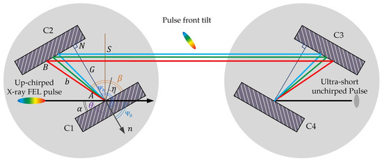
Figure 1.
Configuration of the negative GDD compressor in Bragg geometry. C1, C2, C3, and C4 are four identical asymmetric-cut multilayers or crystals.
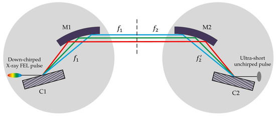
Figure 2.
Configuration of positive GDD compressor in Bragg geometry. C1 and C2 are two identical asymmetric-cut multilayers or crystals.
2.1. Angular Dispersion of Asymmetry-Cut Crystals and Multilayers
The angular dispersion of asymmetric-cut crystals was first investigated in [44]. Essentially, the angular dispersion of asymmetric-cut crystals (multilayers) is the refractive effect at the interface between vacuum and the surface of crystals (multilayers). It is well known that pulse compressors consist of a couple of dispersive optics, such as gratings and prisms. Similar to blazed grating, asymmetric-cut crystals and asymmetric-cut multilayers can serve as dispersive devices in the X-ray regime. For asymmetric-cut crystals and multilayers, the Bragg condition can be equivalently expressed as
where , m, and are the wavelength, diffraction order, and asymmetry angle, respectively. , where d is the lattice spacing of crystals or the period of multilayers. The angles and present the angles between the crystal surface vector to the incident vector and the reflected vector, respectively. More details about the definitions of the angles can be found in Appendix A. It is obvious that Equation (1a) is similar to the grating equation. The equation of the angular dispersion of asymmetric-cut crystals and multilayers is given by
where is the asymmetry ratio. It should be stressed that there is no angular dispersion in symmetric-cut geometry (), and dispersion only exists in asymmetric-cut geometry (). This is the reason why asymmetric-cut crystals and multilayers are adopted as the dispersion device of X-ray pulse compressors. The derivation process of Equation (2) is given in Appendix A.
2.2. Two Typical X-ray Pulse Compressors
Figure 1 shows a typical negative GDD X-ray pulse compressor consisting of four identical dispersion devices, which can be asymmetric-cut crystals or asymmetric-cut multilayers. Because of the symmetry of the negative GDD compressor, here, we only discuss the geometry of the two devices (C1 and C2) on the left. Figure 2 shows a typical positive GDD X-ray pulse compressor. The focal lengths of the two concave mirrors M1 and M2 are and , respectively. The distance between M1 and M2 is . The distance from the first dispersion device to is , while that of the second dispersion device to is . The optical path of the compressor can be written as
For the negative GDD X-ray pulse compressor, = 0, and G is the distance between the two devices. We take the negative sign in Equation (3). For the positive GDD X-ray pulse compressor, , and . We take the positive sign in Equation (3). By differentiating Equation (3) with respect to the wavelength and combining with Equation (2), we can obtain the path difference for different wavelengths
After going through the compressors, the phase change of the pulse is given by
where and . The parameter is the phase correction factor. The positive and negative signs in Equations (4) and (5) correspond to the positive GDD compressor and negative GDD compressor, respectively. The dispersion coefficients of the X-ray compressors are expressed as
where c is the speed of light. In Equation (6a–c), the positive sign corresponds to the negative GDD compressor, and the negative sign corresponds to the positive GDD compressor. Here, we need to pay attention to the sign of the angles and , and more details can be found in Appendix A.
3. Dispersion of X-ray Penetration Effect
X-rays can penetrate into the crystal or multilayer, and the penetration depth is frequency-dependent. We call this effect penetration dispersion. The GDD caused by the penetration dispersion can lead to over-compression or under-compression. In this section, we investigate the penetration dispersion effect of asymmetric-cut crystals and multilayers. The nonlinear dispersion of the penetration effect is studied in Section 3.1. The quantification of penetration dispersion is analyzed in Section 3.2
3.1. Penetration Dispersion
According to the dynamical theory of X-ray diffraction, the amplitudes of the reflectivity and transmissivity can be obtained theoretically (Appendix B and Appendix C). Here, we rewrite the amplitudes and as
Here, we can obtain the dispersion coefficients of the penetration effect
where can be or in Equation (7). The first-order dispersion coefficient describes GD. The second-order coefficient is the GDD of the penetration effect. It is difficult to obtain the mathematical expression of from Equations (A5) and (A9). Therefore, we numerically investigate the dispersion of the penetration effect. In the following investigation, we focus the discussion on the Bragg geometry, and the formulas of amplitude and intensity adopt the thick crystal approximation from Equation (A9).
The GD describes the time delay of different wavelength components. The GDD describes the stretching of compression of a pulse. Figure 3a–c present the results of the GDD for the Mo-Si multilayer, Si(111), and C(400), respectively. Figure 3d–f show the results of the GD for the Mo-Si multilayer, Si(111), and C(400), respectively. The curves in different colors correspond to different asymmetry ratios. The dash lines in the subfigures are the rocking curves. Here, the period of the Mo-Si multilayer is 2 nm, and the thicknesses of Mo and Si are 0.5 nm and 1.5 nm. The results show that the curves of the GDD for the Mo-Si multilayer, Si(111), and C(400) are nonlinear. In practice, the nonlinear characteristic of the GDD for other types of crystals and periodic multilayers is universal. A small bandwidth of reflectivity is associated with a larger GDD. This nonlinear dispersion of periodical multilayers and crystals could lead to the over-compression or under-compression of X-ray pulse compressors.
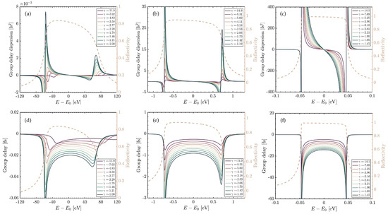
Figure 3.
The GD and GDD of Mo-Si multilayer, Si(111), and C(400). Here, the central photon energy is 10 keV, and the period of Mo-Si multilayer () is 2 nm. The subplots (a–c) represent the GDD of Mo-Si multilayer, Si(111), and C(400), respectively. The subplots (d–f) are corresponding to the GD of Mo-Si multilayer, Si(111), and C(400), respectively. Here, the lines with different colors are related to different asymmetry ratios. The asymmetry ratios of the dashed rocking curves for Mo-Si multilayer, Si(111), and C(400) are −3.58, −4.11, and −3.96, respectively.
3.2. Intrinsic Pulse Stretching
The nonlinear dispersion of the penetration effect will result in an intrinsic stretching of an input X-ray pulse. However, it does not mean the nonlinear dispersion will make a big effect on the X-ray pulse compressors. We need more evaluation in different situations. Here, we define a characteristic time and a characteristic GDD :
where , and . To avoid the overestimation of and , the integral interval should depend on the bandwidth which corresponds to the pulse after being reflecting by the crystals or multilayers. For example, if the bandwidth of the input pulse is broader than the bandwidth of the rocking curve, integration can be performed in (,∞), and corresponds to the bandwidth of the rocking curve. If the bandwidth of the input pulse is narrower than that of the rocking curve, the bounds of the integral interval are determined by the bandwidth of the input pulse, and is equal to the bandwidth of the input pulse.
The characteristic time is the measure of the pulse stretching associated with an input pulse, and this stretching is induced by the dispersion of the crystals or multilayers. The is the characteristic GDD, which nominally produces the pulse stretching of . Here, the integration of Equation (9) is carried out in (,∞). Figure 4a–c present the , bandwidth of the rocking curves, and of Silicon. Figure 4d–f present the , bandwidth of the rocking curves, and of diamond. The results indicate that the characteristic time caused by the penetration dispersion for different atomic planes is different, and a larger corresponds to a narrower bandwidth. The characteristic time represents the intrinsic stretching, which could result in the over-compression or under-compression of X-ray pulse compressors.
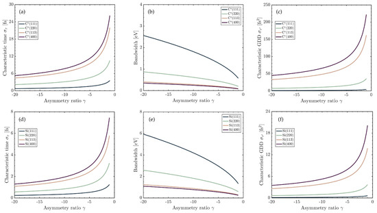
Figure 4.
Subplots (a–c) and (d–f) illustrate the characteristic time , bandwidth, and characteristic GDD of silicon and diamond for different atomic planes, respectively. Here, the calculation is based on the thick crystal model. The lines with different colors correspond to different atomic planes.
In the application of X-ray pulse compressors, it is important to estimate the extra dispersion caused by the penetration effect and, in particular, calculate the effective and . We mentioned that the effective and depend on the integral interval of Equation (9). Figure 5a,b show the effective of the Mo-Si multilayer and Ge(111) as a function of the asymmetry ratio and the normalized range of the integral interval. Here, the period of the Mo-Si multilayer is 2 nm, and the thicknesses of Mo and Si are 0.5 nm and 1.5 nm. The integral interval is centered around the Bragg photon energy and is normalized by the Darwin width of the rocking curve. When the integral interval is smaller than Darwin width , for a given asymmetry ratio, the effective grows as the range increases for the integral interval. When the integral interval is larger than Darwin width , the effective slowly increases until it tends to a constant. To mitigate the impact of nonlinear dispersion, we suggest that large bandwidth multilayers or crystals can be adopted in the design of X-ray pulse compressors. Moreover, it could not be better if the bandwidth of the chirped input X-ray pulse is within the Darwin width and is away from the strong nonlinear dispersion region (two edges of the rocking curve).
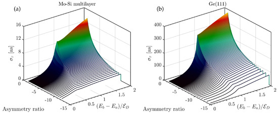
Figure 5.
The effective characteristic time as a function of asymmetry ratio and the range of integral interval. (a) The effective of Mo-Si multilayer with 2 nm period. (b) The effective of Ge(111). Here, the central photon energy is 10 keV.
4. Compressor Configuration Optimization
Having understood the dispersion caused by the penetration effect, we investigate the configuration optimization (dispersion compensation) of X-ray pulse compressors in this section. We first formulate the optimization method in Section 4.1. Then, we discuss an example of chirped X-ray FEL pulse compression in Section 4.2.
4.1. Optimization Method
For pulse compression, we must design a compressor whose GDD cancels the second-order spectral phase of the chirped pulse. Here, we expand the spectral phase of a chirped pulse in the Taylor series
To compress the linear chirped X-ray pulse, the second-order spectral phase should satisfy
where is the GDD produced by the angular dispersion, as described in Equation (6). is the effective characteristic GDD caused by penetration effect. is the number of asymmetric-cut crystals (multilayers). For a given duration of a linear chirped X-ray pulse, the optimal distance G is calculated as
where is the number of asymmetric-cut crystals (multilayers), and is the effective wavelength range. In this paper, we use , , and to represent the normalized bandwidth. Note that the negative GDD compressor can be adopted for the case of linear up-chirp X-ray pulse compression, and Equations (11) and (12) choose the plus sign. The positive GDD compressor can be used for the linear down-chirp X-ray pulse compression, and Equations (11) and (12) choose the minus sign. The optimization of the distance G is the key to realize pulse compression. To find the optimal G, the penetration effect cannot be neglected, especially for multiple reflection compressors.
4.2. Application in Chirped XFEL Pulse Compression
In the previous sections, we investigated the penetration dispersion of crystals and multilayers. By optimizing the distance G, the penetration dispersion can be mitigated. In this subsection, we numerically investigate chirped X-ray pulse compression based on LCLS-II-HE parameters.
In our simulation, the central photon energy of the FEL pulse is 10 keV, and we adopt an asymmetric-cut Mo-Si multilayer compressor and an asymmetric-cut Ge(111) compressor to compress the chirped XFEL pulse. Table 1 provides the relevant parameters for these two compressors. The geometry of the compressor is shown in Figure 1. For the Ge(111) compressor, the asymmetry angle is . The acceptance bandwidth of the Ge(111) compressor is about 20 eV. For the Mo-Si multilayer compressor, the period d, the thickness ratio of Mo, and the asymmetry angle are 2 nm, 0.25, and , respectively. The acceptance bandwidth is about 120 eV, which is larger than the bandwidth of the chirped XFEL pulse (70 eV). The relevant parameters of the compressor are listed in Table 1. The optimized gap G of the asymmetric-cut Ge(111) compressor is larger than that of the multilayer compressor. This is because the penetration dispersion of G(111) is larger than that of the Mo-Si multilayer. Therefore, a larger G is needed to compensate for the dispersion.

Table 1.
The parameters of the crystal and multilayer compressors.
In the next step, we apply the two types of compressors to compress the chirped XFEL pulse. Using the software GENESIS 1.3 [48], three-dimensional FEL simulations are carried out based on the parameters of LCLS-II-HE as shown in Table 2. When the up-chirped photon beam passes through the compressor, the photons, selected by the compressor, are compressed to an ultrashort duration. Figure 6 illustrates the numerical simulation results. The normalized electron bunch energy chirp is 1.1 /fs (3.34 MeV/fs), and the electron bunch length is 10 fs. The normalized chirp of the XFEL pulse at saturation is 2.2/fs (8.36 eV/fs), and the pulse duration is 10 fs, as shown in Figure 6a,d. By optimizing the distance G of the compressor, the chirped XFEL pulse can be compressed to an unchirped pulse. Figure 6b,e are the Wigner phase space and power distribution after the Mo-Si asymmetric-cut multilayer compressor, and the pulse duration is compressed to 0.79 fs. After going through the asymmetric-cut Ge(111) compressor, the Wigner phase space and power distribution of the pulse are shown in Figure 6c,f, and we obtain an unchirped pulse with the duration of 0.70 fs. We can find that the bandwidth of the pulse after the crystal compressor decreases to 20 eV, which corresponds to the bandwidth acceptance of the asymmetric-cut Ge(111) compressor. It should be stressed that the pulse duration achieved in the simulation does not reach the Fourier transform limited pulse duration. Therefore, it is possible to realize a shorter pulse duration.
Table 2.
The relevant parameters of LCLS-II-HE.
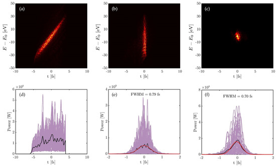
Figure 6.
(a) The Wigner phase space of the up-chirped XFEL pulse before compression (left is the bunch head). (b) The Wigner phase space of XFEL pulse after the Mo-Si multilayer compressor. (c) The Wigner phase space of the XFEL pulse after the crystal compressor. (d) The XFEL pulse with a flattop distribution and 10 fs duration before compression. (e) The XFEL pulse with 0.79 fs FWHM duration after the Mo-Si multilayer compressor. (f) The XFEL pulse with 0.70 fs FWHM duration after the crystal compressor. Here, the black and red curves in (d–f) are the average over 50 simulation runs and the Gaussian fitting. The purple curves refer to single-shot simulations. The central photon energy is 10 keV.
It is worth pointing out that there are two situations in the simulation: (a) The bandwidth of the chirped XFEL is larger than the acceptance bandwidth of the compressor. (b) The bandwidth of the chirped XFEL is smaller than or equal to the acceptance bandwidth of the compressor. For situation (a), only a part of the FEL pulse is selected and compressed. It can be considered a bandpass compressor which corresponds to the asymmetric-cut Ge(111) compressor. For situation (b), all the photons of the XFEL pulse are compressed, except for the absorbed photons. This situation corresponds to the asymmetric-cut Mo-Si multilayer compressor.
The optimal pulse duration after the compressor of the two cases can be estimated by
where and are the bandwidth and the duration of the input linear chirped X-ray pulse, respectively. is the intrinsic bandwidth of the unchirped FEL pulse. It is obvious that a larger energy chirp and a smaller intrinsic bandwidth contribute to a shorter duration of the output pulse. Therefore, the output pulse duration can be optimized by controlling the intrinsic bandwidth and the energy chirp of the input XFEL pulse.
5. Discussion
Ultrashort pulses are a powerful tool for exploring transient dynamic processes. Using the chirped pulse compression approach, it is possible to generate attosecond pulses at XFELs in principle. To achieve chirped pulse compression in the X-ray regime, investigating X-ray pulse compressors is crucial. For soft X-rays, diffraction gratings and asymmetric-cut multilayers are suggested [41,42], while for hard X-rays, asymmetric-cut multilayers, strained crystals [43], and asymmetric-cut crystals [44,45] are recommended. The principle behind these devices is based on the angular dispersion. However, the extra dispersion induced by the penetration effect of X-rays has not been explored.
In this study, we investigated the penetration dispersion of asymmetric-cut multilayers and asymmetric-cut crystals. By estimating the extra dispersion caused by the penetration effect, we present the strategy of dispersion compensation which is carried out by the optimization of the configuration of X-ray pulse compressors. Here, we present two suggestions: (1) To avoid producing a large extra GDD, broadband crystals, and multilayers should be adopted. (2) To mitigate the nonlinear dispersion, the effective reflection region should be in the center of the Darwin width and be away from the two edges of the rocking curve.
6. Conclusions
In conclusion, this study investigated the penetration dispersion of asymmetric-cut multilayers and crystals, and defined two important parameters, namely, the intrinsic characteristic stretching time and the effective characteristic GDD . Our numerical calculations demonstrate that a narrow bandwidth device induces a large dispersion, while a broadband device produces a small dispersion. Additionally, we found that the nonlinear dispersion produced by the penetration effect is strong around the two edges of the rocking curve and weak in the core of the rocking curve. Based on these results, we recommend using broadband asymmetric-cut crystals and asymmetric-cut multilayers in X-ray pulse compressors, with the optimal effective region of reflection being located in the weak nonlinear region. Furthermore, the effective nonlinear dispersion can be mitigated by optimizing the configuration of X-ray pulse compressors, and we presented the optimization method for two typical configurations. Lastly, we discussed the application in chirped XFEL pulse compression using the parameters of LCLS-II-HE. This research provides useful insights for the design and optimization of X-ray pulse compressors.
Author Contributions
Conceptualization, C.Y., J.W. and W.Z.; Funding acquisition, C.Y.; Investigation, C.Y., K.H., Y.Z. and W.Z.; Software, C.Y., K.H., X.W., Q.L. and Z.X.; Supervision, J.W. and W.Z.; Visualization, Y.Z.; Writing—original draft, C.Y.; Writing—review editing, J.W. and W.Z. All authors have read and agreed to the published version of the manuscript.
Funding
This research was funded by the National Natural Science Foundation of China (Grant No. 12005135 and 22288201), National Key R&D Program of China (Grant No. 2018YFE0203000), and Scientific Instrument Developing Project of the Chinese Academy of Sciences (Grant No. GJJSTD20190002).
Institutional Review Board Statement
Not applicable.
Informed Consent Statement
Not applicable.
Data Availability Statement
Not applicable.
Conflicts of Interest
The authors declare no conflict of interest.
Appendix A. Notation Convention of Angles
In this work, we follow the sign convention of angles adopted by Authier [49]. The reciprocal crystal lattice vector is , and the trace of the lattice planes is . The directions of the incident beam and diffracted beam are given by the unit vectors and , respectively. The directions of , , , and are oriented in Figure A1. is defined as the normal directed into the crystal surface. The asymmetry angle is defined by , which describes the angle between the crystal surface and the parallel reflecting atomic planes. , , and are the angles between and the incident vector, the reflection vector, and the lattice trace, respectively: , , . The Bragg angle is the included angle between the reflecting atomic plane and the incident vector. Here, we define , . Eventually, we have the following relations:
The parameters , are the angles between the crystal surface vactor to the incident vector and the reflected vector , respectively: , :

Figure A1.
Orientation of angles in Bragg geometry (left) and Laue geometry (right).
Figure A1.
Orientation of angles in Bragg geometry (left) and Laue geometry (right).

To describe the asymmetric geometry, we set and . Then the asymmetry ratio can be defined as
The asymmetry ratio is always negative for Bragg geometry , while it is all positive for Laue geometry . For symmetric Bragg geometry, and . For symmetric Laue geometry, and . In this paper, we focus the investigation on Bragg geometry. Differentiating Equation (1a) leads to the equation of angular dispersion:
Appendix B. Dynamical Theory of X-ray Diffraction
The dynamical theory of X-ray diffraction is a graceful model to mimic the multiple diffractions of X-rays inside a perfect crystal [49,50]. By solving Maxwell’s equations inside the periodic materials, the amplitudes of the reflected and refracted beams can be obtained. According to the dynamical theory of X-ray diffraction, for a thick crystal with thickness l, the diffraction amplitude of the reflected beam () and the refracted beam () in Bragg geometry can be expressed as
and the intensities of the reflected and refracted beams are expressed as
Here, , which is the angular frequency deviation from the Bragg condition. is the sign of . The amplitude and intensity of the reflected beam in Bragg geometry for the thick crystal are given by
where denotes the sign of the real part of y. The dynamical diffraction theory gives the angular width of the Bragg reflection, which is called the Darwin width
where denotes the Darwin width in symmetric diffraction geometry. Expressing the Darwin width in the units of photon energy by using the differential equation of Bragg condition , the spectral acceptance of crystal can be written as
where is the Bragg photon energy. The acceptance of the input bandwidth is proportional to the square root of . The asymmetric crystal () can increase the incident spectral acceptance.
Appendix C. Asymmetry-Cut Multilayer
For multilayers, there are two approaches to calculate the diffraction, including optical matrix theory [51,52,53] and the dynamical theory. Although the optical matrix theory can describe the diffraction by arbitrary nonperiodic multilayer, this method is only valid for symmetric Bragg geometry (). In this work, we focus the discussion on periodic asymmetric-cut multilayer, so the dynamical diffraction theory model is adopted. In the following, dynamical diffraction theory will be briefly introduced. The difference between crystal and multilayer is the calculation of the Fourier coefficients of the electric susceptibility. For crystal, we have
where () is a reciprocal vector. Equation (A12) can be further expressed as
where , and are the structure factor, the volume of unit cell and the wavelength of incident wave, respectively. is the classical radius of the electron.
The multilayer can be regarded as a two-dimensional crystal. Therefore, we need to reconstruct the Fourier coefficients of the electric susceptibility, and Equation (A12) can be modified as
where d is the period of the structure of the multilayer. The electric susceptibility within each layer in real space can be written as
where , A, are the density, molar mass, and Avogadro’s number, respectively. is the form factor of atom j, and and are the anomalous dispersion corrections.
For the case of the multilayer model with two materials, let us assume that the material interfaces are sharp, which means there is no interdiffusion between the two materials. The electric susceptibility can be expressed as
where , are the ratios of the thickness of the two layers to the period. According to the definition in Equation (A14), we can easily obtain
The reflectivity and transmissivity of the multilayer can be calculated by substituting Equation (A17) into Equation (A5) or Equation (A9). If the structure of the multilayer is extended to more than two layers within one period, we can similarly calculate the electric susceptibility. It is needed to point out that the limitation of dynamical diffraction theory requires strict periodicity.
References
- Hentschel, M.; Kienberger, R.; Spielmann, C.; Reider, G.A.; Milosevic, N.; Brabec, T.; Corkum, P.; Heinzmann, U.; Drescher, M.; Krausz, F. Attosecond metrology. Nature 2001, 414, 509–513. [Google Scholar] [CrossRef] [PubMed]
- Drescher, M.; Hentschel, M.; Kienberger, R.; Tempea, G.; Spielmann, C.; Reider, G.A.; Corkum, P.B.; Krausz, F. X-ray Pulses Approaching the Attosecond Frontier. Science 2001, 291, 1923–1927. [Google Scholar] [CrossRef] [PubMed]
- Chang, Z.; Corkum, P. Attosecond photon sources: The first decade and beyond [Invited]. J. Opt. Soc. Am. B 2010, 27, B9–B17. [Google Scholar] [CrossRef]
- Sansone, G.; Poletto, L.; Nisoli, M. High-energy attosecond light sources. Nat. Photonics 2011, 5, 655–663. [Google Scholar] [CrossRef]
- Krausz, F.; Stockman, M. Attosecond metrology: From electron capture to future signal processing. Nat. Photonics 2014, 8, 205–213. [Google Scholar] [CrossRef]
- Kraus, P.M.; Mignolet, B.; Baykusheva, D.; Rupenyan, A.; Horný, L.; Penka, E.F.; Grassi, G.; Tolstikhin, O.I.; Schneider, J.; Jensen, F.; et al. Measurement and laser control of attosecond charge migration in ionized iodoacetylene. Science 2015, 350, 790–795. [Google Scholar] [CrossRef] [PubMed]
- Baker, S.; Robinson, J.S.; Haworth, C.A.; Teng, H.; Smith, R.A.; Chirilă, C.C.; Lein, M.; Tisch, J.W.G.; Marangos, J.P. Probing Proton Dynamics in Molecules on an Attosecond Time Scale. Science 2006, 312, 424–427. [Google Scholar] [CrossRef]
- Krausz, F.; Ivanov, M. Attosecond physics. Rev. Mod. Phys. 2009, 81, 163. [Google Scholar] [CrossRef]
- Schultze, M.; Bothschafter, E.M.; Sommer, A.; Holzner, S.; Schweinberger, W.; Fiess, M.; Hofstetter, M.; Kienberger, R.; Apalkov, V.; Yakovlev, V.S.; et al. Controlling dielectrics with the electric field of light. Nature 2014, 493, 75–78. [Google Scholar] [CrossRef]
- Seres, J.; Seres, E.; Verhoef, A.J.; Tempea, G.; Streli, C.; Wobrauschek, P.; Yakovlev, V.; Scrinzi, A.; Spielmann, C.; Krausz, F. Source of coherent kiloelectronvolt X-rays. Nature 2005, 433, 596. [Google Scholar] [CrossRef]
- Popmintchev, T.; Chen, M.; Popmintchev, D.; Arpin, P.; Brown, S.; Ališauskas, S.; Andriukaitis, G.; Balčiunas, T.; Mücke, O.D.; Pugzlys, A.; et al. Bright Coherent Ultrahigh Harmonics in the keV X-ray Regime from Mid-Infrared Femtosecond Lasers. Science 2012, 336, 1287–1291. [Google Scholar] [CrossRef]
- Chang, Z.; Rundquist, A.; Wang, H.; Murnane, M.M.; Kapteyn, H.C. Generation of Coherent Soft X Rays at 2.7 nm Using High Harmonics. Phys. Rev. Lett. 1997, 79, 2967–2970. [Google Scholar] [CrossRef]
- Chen, M.C.; Arpin, P.; Popmintchev, D.; Gerrity, M.; Zhang, B.; Seaberg, M.; Murnane, M.M.; Kapteyn, H. Bright, Coherent, Ultrafast Soft X-ray Harmonics Spanning the Water Window from a Tabletop Light Source. Phys. Rev. Lett. 2010, 105, 173901. [Google Scholar] [CrossRef] [PubMed]
- Emma, P.; Akre, R.; Akre, R.; Arthur, J.; Bionta, R.; Bostedt, C.; Bozek, J.; Brachmann, A.; Bucksbaum, P.; Coffee, R.; et al. First lasing and operation of an ångstrom-wavelength free-electron laser. Nat. Photonics 2010, 4, 641–647. [Google Scholar] [CrossRef]
- Ishikawa, T.; Aoyagi, H.; Aoyagi, H.; Asaka, T.; Asano, Y.; Azumi, N.; Bizen, T.; Ego, H.; Fukami, K.; Fukui, T.; et al. A compact X-ray free-electron laser emitting in the sub-ångstrom region. Nat. Photonics 2012, 6, 540–544. [Google Scholar] [CrossRef]
- Allaria, E.; Castronovo, D.; Castronovo, D.; Cinquegrana, P.; Craievich, P.; Dal Forno, M.; Danailov, M.; D’Auria, G.; Demidovich, A.; De Ninno, G.; et al. Two-stage seeded soft-X-ray free-electron laser. Nat. Photonics 2013, 7, 913–918. [Google Scholar] [CrossRef]
- Kang, H.S.; Min, C.K.; Heo, H.; Kim, C.; Yang, H.; Kim, G.; Nam, I.; Baek, S.Y.; Choi, H.-J.; Mun, G.; et al. Hard X-ray free-electron laser with femtosecond-scale timing jitter. Nat. Photonics 2017, 11, 708–713. [Google Scholar] [CrossRef]
- Altarelli, M. The European X-ray free-electron laser facility in Hamburg. Nucl. Instruments Methods Phys. Res. Sect. Beam Interact. Mater. Atoms 2011, 269, 2845–2849. [Google Scholar] [CrossRef]
- Milne, C.J.; Schietinger, T.; Aiba, M.; Alarcon, A.; Alex, J.; Anghel, A.; Arsov, V.; Beard, C.; Beaud, P.; Bettoni, S.; et al. SwissFEL: The Swiss X-ray Free Electron Laser. Appl. Sci. 2017, 7, 720. [Google Scholar] [CrossRef]
- Kondratenko, A.M.; Saldin, E.L. Generation of coherent radiation by a relativistic electron beam in an undulator. Part. Accel. 1980, 10, 207–216. [Google Scholar]
- Bonifacio, R.; Pellegrini, C.; Narducci, L. Collective instabilities and high-gain regime in a free electron laser. Opt. Commun. 1984, 50, 373–378. [Google Scholar] [CrossRef]
- Feldhaus, J.; Saldin, E.; Schneider, J.; Schneidmiller, E.; Yurkov, M. Possible application of X-ray optical elements for reducing the spectral bandwidth of an X-ray SASE FEL. Opt. Commun. 1997, 140, 341–352. [Google Scholar] [CrossRef]
- Geloni, G.; Kocharyan, V.; Saldin, E. A novel self-seeding scheme for hard X-ray FELs. J. Mod. Opt. 2011, 58, 1391–1403. [Google Scholar] [CrossRef]
- Amann, J.; Berg, W.; Blank, V.; Decker, F.-J.; Ding, Y.; Emma, P.; Feng, Y.; Frisch, J.; Fritz, D.; Hastings, J.; et al. Demonstration of self-seeding in a hard-X-ray free-electron laser. Nat. Photonics 2012, 6, 693–698. [Google Scholar] [CrossRef]
- Yu, L.H. Generation of intense uv radiation by subharmonically seeded single-pass free-electron lasers. Phys. Rev. A 1991, 44, 5178–5193. [Google Scholar] [CrossRef]
- Stupakov, G. Using the Beam-Echo Effect for Generation of Short-Wavelength Radiation. Phys. Rev. Lett. 2009, 102, 074801. [Google Scholar] [CrossRef]
- Di Mitri, S.; Allaria, E.; Appio, R.; Badano, L.; Bassanese, S.; Bencivenga, F.; Borga, A.; Bossi, M.; Busetto, E.; Callegari, C.; et al. Commissioning and Initial Operations of FERMI@Elettra. In Proceedings of the 2nd International Particle Accelerator Conference, San Sebastian, Spain, 4–9 September 2011; pp. 918–922. [Google Scholar]
- Zholents, A.; Fawley, W. Proposal for Intense Attosecond Radiation from an X-Ray Free-Electron Laser. Phys. Rev. Lett. 2004, 92, 224801. [Google Scholar] [CrossRef]
- Zholents, A. Method of an enhanced self-amplified spontaneous emission for x-ray free electron lasers. Phys. Rev. Spec. Top. Accel. Beams 2005, 8, 040701. [Google Scholar] [CrossRef]
- Ding, Y.; Huang, Z.; Ratner, D.; Bucksbaum, P.; Merdji, H. Generation of attosecond x-ray pulses with a multicycle two-color enhanced self-amplified spontaneous emission scheme. Phys. Rev. Spec. Top. Accel. Beams 2009, 12, 060703. [Google Scholar] [CrossRef]
- Zholents, A.; Penn, G. Obtaining attosecond X-ray pulses using a self-amplified spontaneous emission free electron laser. Phys. Rev. Spec. Top. Accel. Beams 2005, 8, 050704. [Google Scholar] [CrossRef]
- Emma, P.; Bane, K.; Cornacchia, M.; Huang, Z.; Schlarb, H.; Stupakov, G.; Walz, D. Femtosecond and Subfemtosecond X-Ray Pulses from a Self-Amplified Spontaneous-Emission-Based Free-Electron Laser. Phys. Rev. Lett. 2004, 92, 074801. [Google Scholar] [CrossRef] [PubMed]
- Xiang, D.; Huang, Z.; Stupakov, G. Generating Intense Attosecond X-ray Pulses Using Ultraviolet-Laser-Induced Microbunching in Electron Beams. Phys. Rev. Spec. Top. Accel. Beams 2009, 12, 060701. [Google Scholar] [CrossRef]
- Huang, S.; Ding, Y.; Feng, Y.; Hemsing, E.; Huang, Z.; Krzywinski, J.; Lutman, A.A.; Marinelli, A.; Maxwell, T.J.; Zhu, D. Generating Single-Spike Hard X-Ray Pulses with Nonlinear Bunch Compression in Free-Electron Lasers. Phys. Rev. Lett. 2017, 119, 154801. [Google Scholar] [CrossRef] [PubMed]
- Bane, K.; Stupakov, G. Corrugated pipe as a beam dechirper. Nucl. Instrum. Methods Phys. Res. Sect. Accel. Spectrometers Detect. Assoc. Equip. 2012, 690, 106–110. [Google Scholar] [CrossRef]
- Emma, P.; Venturini, M.; Bane, K.L.F.; Stupakov, G.; Kang, H.-S.; Chae, M.S.; Hong, J.; Min, C.-K.; Yang, H.; Ha, T.; et al. Experimental Demonstration of Energy-Chirp Control in Relativistic Electron Bunches Using a Corrugated Pipe. Phys. Rev. Lett. 2014, 112, 034801. [Google Scholar] [CrossRef] [PubMed]
- Lutman, A.; Maxwell, T.J.; MacArthur, J.P.; Guetg, M.; Berrah, N.; Coffee, R.N.; Ding, Y.; Huang, R.N.C.Z.; Marinelli, A.; Moeller, S.; et al. Fresh-slice multicolour X-ray free-electron lasers. Nat. Photonics 2016, 10, 745–750. [Google Scholar] [CrossRef]
- Guetg, M.W.; Lutman, A.A.; Ding, Y.; Maxwell, T.J.; Huang, Z. Dispersion-Based Fresh-Slice Scheme for Free-Electron Lasers. Phys. Rev. Lett. 2018, 120, 264802. [Google Scholar] [CrossRef]
- Pellegrini, C. High power femtosecond pulses from an X-ray SASE-FEL. Nucl. Instrum. Methods Phys. Res. Sect. Accel. Spectrometers Detect. Assoc. Equip. 2000, 445, 124–127. [Google Scholar] [CrossRef]
- Poletto, L.; Frassetto, F. Grating configurations to compress free-electron laser pulses. J. Synchrotron Radiat. 2018, 25, 52–58. [Google Scholar] [CrossRef]
- Bajt, S.; Chapman, H.N.; Aquila, A.; Gullikson, E. High-efficiency X-ray gratings with asymmetric-cut multilayers. J. Opt. Soc. Am. A 2012, 29, 216–230. [Google Scholar] [CrossRef]
- Prasciolu, M.; Haase, A.; Scholze, F.; Chapman, H.N.; Bajt, S. Extended asymmetric-cut multilayer X-ray gratings. Opt. Express 2015, 23, 15195–15204. [Google Scholar] [CrossRef] [PubMed]
- Chapman, H.; Nugent, K. X-ray pulse compression using strained crystals. Opt. Commun. 2002, 205, 351–359. [Google Scholar] [CrossRef]
- Shvyd’ko, Y.V.; Lerche, M.; Kuetgens, U.; Rüter, H.D.; Alatas, A.; Zhao, J. X-ray Bragg Diffraction in Asymmetric Backscattering Geometry. Phys. Rev. Lett. 2006, 97, 235502. [Google Scholar] [CrossRef] [PubMed]
- Hrdy, J.; Oberta, P. Possibility of X-ray pulse compression using an asymmetric or inclined double-crystal monochromator. J. Synchrotron Radiat. 2013, 20, 550–554. [Google Scholar] [CrossRef]
- Li, H.; MacArthur, J.; Littleton, S.; Dunne, M.; Huang, Z.; Zhu, D. Femtosecond-Terawatt Hard X-Ray Pulse Generation with Chirped Pulse Amplification on a Free Electron Laser. Phys. Rev. Lett. 2022, 129, 213901. [Google Scholar] [CrossRef] [PubMed]
- Weiner, A.M. Ultrafast Optics. 2009, Chapter 4. Available online: https://onlinelibrary.wiley.com/doi/book/10.1002/9780470473467 (accessed on 26 March 2023).
- Reiche, S. GENESIS 1.3: A fully 3D time-dependent FEL simulation code. Nucl. Instrum. Methods Phys. Res. Sect. 1999, 429, 243–248. [Google Scholar] [CrossRef]
- Authier, A. Dynamical Theory of X-ray Diffraction; Oxford University: Oxford, UK, 2001. [Google Scholar]
- Yuri, S. X-ray Optics—High-Energy-Resolution Applications; Springer: Berlin/Heidelberg, Germany, 2004. [Google Scholar]
- Sears, V.F. Dynamical Diffraction in Periodic Multilayers. Acta Crystallogr. Sect. 1997, 53, 649–662. [Google Scholar] [CrossRef]
- Born, M.; Wolf, E. Principles of Optics: 60th Anniversary Edition, 7th ed.; Cambridge University Press: Cambridge, UK, 2019. [Google Scholar] [CrossRef]
- Windt, D.L. IMD—Software for modeling the optical properties of multilayer films. Comput. Phys. 1998, 12, 360–370. [Google Scholar] [CrossRef]


Disclaimer/Publisher’s Note: The statements, opinions and data contained in all publications are solely those of the individual author(s) and contributor(s) and not of MDPI and/or the editor(s). MDPI and/or the editor(s) disclaim responsibility for any injury to people or property resulting from any ideas, methods, instructions or products referred to in the content. |
© 2023 by the authors. Licensee MDPI, Basel, Switzerland. This article is an open access article distributed under the terms and conditions of the Creative Commons Attribution (CC BY) license (https://creativecommons.org/licenses/by/4.0/).