Abstract
Industrial effluents often contain azeotropic mixtures that are difficult to separate by conventional distillation. An illustrative case is the methanol/methyl acetate/ethyl acetate (MA/ME/EA) mixture. To address these challenges, this work studies the conceptual design and optimization of the reactive distillation-based hybrid processes for separating the MA/ME/EA mixture with an EA-rich feed composition (0.25/0.20/0.55 mol fraction). An improved triple-column extractive–reactive distillation with a side-draw product (TCERD-SP) and its heat-integrated variant (TCERD-SP-HI) have been developed. In the TCERD-SP process, EA is strategically withdrawn as a side product, reconfiguring the extractive column into integrated pre-separation and entrainer-recovery sections, thereby reducing entrainer and energy demands. A four-step process design methodology is applied, including thermodynamics analysis, conceptual design, rigorous optimization via Aspen Plus integrated with the genetic algorithm to minimize total annual cost (TAC), and comparative evaluation of economic and environmental performance. The results show that the basic double-column pre-separation-reactive distillation (DCPSRD) process, optimal for a previous feed composition, exhibits unsatisfactory TAC performance for this EA-rich feed composition. Among the configurations studied, the TCERD-SP process exhibits superior performance, saving TAC by 8.4% and 14.4% compared to the TCERD and DCPSRD processes, respectively. In addition, based on the advantage of convenient heat integration between the side reboiler and the reactive distillation column condenser, the heat-integrated TCERD-SP-HI process achieves a further 10.7% TAC reduction. Thus, for this EA-rich feed examined in this work, the TCERD-SP and TCERD-SP-HI processes are demonstrated as effective solutions for recovering these valuable chemicals.
1. Introduction
The recovery of valuable chemicals from industrial waste streams is critically important for both meeting stringent environmental regulations and promoting a circular economy. However, in practice, many waste streams of the chemical industry contain mixtures with one or more azeotropes, which are difficult to separate. Conventional distillation cannot achieve the required product purity for such mixtures. These challenges have significant environmental and economic implications, motivating the development of special distillation methods, such as extractive distillation (ED), pressure-swing distillation (PSD), and azeotropic distillation (AD) [1,2,3,4], to reclaim valuable components from waste streams and reduce hazardous emissions.
In recent years, to achieve high-purity products and improve distillation efficiency, researchers have increasingly combined the above special methods with chemical reactions. The integration of distillation separation and reaction within the same column, reactive distillation (RD), has emerged as a powerful process intensification strategy [5,6,7]. By consuming one azeotropic component via a chemical reaction, RD effectively shifts the composition trajectory and enables subsequent separation of the remaining components in a single column. These hybrid reaction–separation processes not only simplify flowsheets, but also harness the heat of reaction in situ to reduce overall energy consumption and minimize waste generation [8]. One notable example of RD’s effectiveness is the use of an auxiliary reaction to break azeotropes that include water. For example, adding ethylene oxide (EO) to react with water (an exothermic hydration) has been used to eliminate the water content from azeotropic mixtures [1]. Huang et al. [9] demonstrated that introducing an EO hydration reaction in a reactive distillation scheme can break multiple azeotropes in the ethyl acetate/isopropanol/water system, achieving a lower total annual cost (TAC) and improved environmental performance compared to a conventional extractive distillation process. This RD with the EO approach has proven highly effective for separating water-containing azeotropes and has been adopted in various hybrid schemes. The concept, which was initially applied to break the ethanol/water azeotrope via reactive distillation [1], has since been extended to more complex ternary systems. Recent studies have reported a range of innovative reactive–extractive distillation configurations for multicomponent azeotropes, including double-column or triple-column sequences [10,11]. These works reflect the considerable potential of hybrid RD-based processes to solve separation problems that are infeasible with standard distillation alone. However, they also highlight that each azeotropic system requires careful, case-by-case design to address its unique phase behavior and to ensure economical operation.
Having established RD’s potential, among challenging azeotropic mixtures, the ternary system of methyl acetate (MA), methanol (ME), and ethyl acetate (EA) is particularly noteworthy. In industry, MA, ME, and EA are important solvents and intermediates in coatings and electronic-chemicals manufacturing [12,13,14,15]. All three components are high-volume chemicals, so efficient recovery is industrially important. In addition, the MA/ME/EA system belongs to Serafimov’s class 2.0–2b ternary mixtures, containing two binary minimum-boiling azeotropes, and poses significant separation difficulties [12,13]. Traditional distillation methods like ED or PSD for this ternary mixture demand very large entrainer flows and intensive energy input, and often produce additional by-products or waste streams of low commercial value [9]. These drawbacks motivate the search for more sustainable and value-generating separation techniques.
For the MA/ME/EA system, recent research by Zhu et al. [15] tackled the separation of MA/ME/EA by using a transesterification reaction to effectively circumvent the azeotropic barrier. In their work, a chemical reaction between MA and an added reactant, propylene glycol monomethyl ether (PGME), was carried out in a reactive distillation column. MA was converted into extra ME while simultaneously producing propylene glycol monomethyl ether acetate (PGMEA), which is a high-value solvent used in coatings and electronics. This RD process converted low-value components (MA) into valuable products (PGMEA) while eliminating the difficulty of separating MA. Zhu et al. [15] proposed three RD-based flowsheets for this system: a triple-column reactive–extractive distillation (TCRED), a triple-column extractive–reactive distillation (TCERD), and a double-column pre-separation reactive distillation (DCPSRD). In their optimal design, the DCPSRD configuration achieved the lowest TAC for the feed composition (0.4MA/0.2ME/0.4EA), outperforming their other configurations. The advantages of their RD-based strategy are clear; the transesterification reaction is mildly endothermic and is facilitated by a sodium methoxide catalyst. And the process intensification allows the elimination of a dedicated ME recovery column by generating PGMEA as a valuable coproduct. However, a key insight from Zhu et al. [15] was that the optimal separation strategy strongly relies on the composition of the feed. Hence, the DCPSRD scheme’s superiority may not hold if the feed composition changes. This reveals an important knowledge gap: the effect of feed composition on the feasibility and economics of these hybrid RD processes has not been fully explored. In particular, it is necessary to determine how economic and environmentally friendly each RD-based configuration is when the composition of the waste stream changes, and whether a new or modified process could adapt to the new feed composition for cost-effective separation. Therefore, there are two important issues that were not resolved in the earlier work. First, industrial waste stream composition may vary substantially. For the MA/ME/EA system, a feed composition rich in the heavy component ethyl acetate (0.25MA/0.2ME/0.55EA mole fraction) shifts the azeotropic landscape. Based on the thermodynamic analysis, at such a composition, more reboiler duty may be required to separate EA and MA/ME in the pre-separation column. Consequently, the DCPSRD process that is optimal for the earlier feed may no longer achieve the lowest TAC under these conditions. Therefore, improved alternative configurations are worth exploring and researching.
Accordingly, the objective of this work is to investigate how the EA-rich case (0.25MA/0.2ME/0.55EA) influences the feasibility and economics of hybrid RD-based processes for the MA/ME/EA mixture, and proposes a modified configuration, triple-column extractive–reactive distillation with a side-draw product (TCERD-SP), and a heat-integrated variant (TCERD-SP-HI) that couples a side reboiler to the reactive distillation column condenser. The research is carried out through a four-step approach: thermodynamic analysis, conceptual design, process optimization, and performance evaluation based on economic and environmental evaluation indices. By systematically following these steps, we aim to identify which process configuration is the economically favorable distillation process for the EA-rich feed composition.
2. Methodology
As illustrated in Figure 1, the method workflow comprises four stages: thermodynamic analysis, conceptual design, rapid process optimization, and economic and environmental evaluation. Based on these, we proceed from thermodynamic characterization to flowsheet conceptualization and optimization.
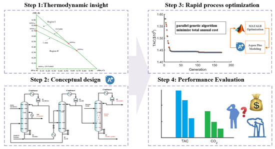
Figure 1.
Method diagram of the four steps of the conceptual design and optimization design.
2.1. Thermodynamics Insights
The phase equilibria are described using the NRTL model with binary interaction parameters compiled as previously reported [15,16]. Binary parameter values and sources are provided in the Supporting Information Table S1. The binary parameters of EA-PGME and EA-PGMEA are obtained from the Aspen Plus database V11, which are estimated via UNIFAC. Model adequacy is verified by comparing NRTL predictions with experimental vapor-liquid equilibrium (VLE) data for MA/ME/EA/chlorobenzene (CB) and PGME/PGMEA/ME/MA [17,18,19]. The T-xy diagrams are shown in Figures S2–S10 [20,21,22,23,24,25]. Although a small amount of experimental data on component pairs is missing, the deviation between the experimental data and the predicted data of most component pairs is within the acceptable range. Therefore, the NRTL model can be regarded as an accurate model. All the simulations of the distillation process are performed in Aspen Plus V11. The ternary diagram of MA/ME/EA is presented in Figure 2. The MA/ME/EA system exhibits two binary azeotropes, which belong to Serafimov’s class 2.0–2b ternary mixtures. At pressures ≥ 4.4 atm, an additional binary azeotrope (EA/MA) appears, altering feasible separation pathways.
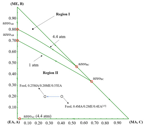
Figure 2.
The ternary diagram of MA/ME/EA at 1 atm and 4.4 atm [15].
In this study, except for feed composition, the design basis, the chemistry, and kinetic parameters are consistent with previous work [15]. The fresh feed flowrate is specified at 100 kmol/h. The product purity of MA, ME, PGMEA, and EA is not less than 0.995 mole fraction, and the entrainer CB is not less than 0.999 mole fraction. The feed composition is 0.25MA/0.2ME/0.55EA mole fraction, compared to the prior feed composition (0.4MA/0.2ME/0.4EA) [15]. The mole fraction of reactant MA decreases by 0.15, the content of EA increases by 0.15, and the content of ME remains unchanged, which is rich in the heavy component EA. The impacts of this composition shift for process design and performance are discussed in the following sections.
The transesterification between MA and PGME to produce PGMEA is selected as the in-column reaction for the reactive distillation system. The chemical equation is as follows. The kinetic parameters of MA-PGME transesterification are given in Table S2. The α denotes activity coefficients rather than molar concentrations. Sodium methoxide is employed as the homogeneous catalyst. To ensure consistency with Aspen Plus, the kinetic parameters are converted, and the catalyst density is assumed to be 945.42 kg/m3 (from Aspen Plus) [12].
2.2. Conceptual Design
Based on the thermodynamic insights, for the separation of the MA/ME/EA ternary system, there are multiple RD-based separation sequences with MA-PGME transesterification reaction, as shown in Figure 3. In sequence (a), fresh feed enters a reactive distillation column (first column), and MA is removed via transesterification reaction between PGME and MA, but two EA-related transesterification reactions (EA-PGME and EA-ME) may also proceed in this column. In the sequences (b) and (c), the fresh feed is first separated into EA product and MA/ME fraction; MA/ME is then fed to a reactive distillation column to produce high-purity ME and PGMEA. Because the EA content in this reactive distillation column is negligible, the two EA-related transesterification reactions can be ignored. Therefore, only the separation sequences (b) and (c) will be used for the separation of MA/ME/EA, while sequence (a) will not be considered in this work.
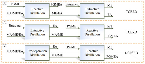
Figure 3.
Different separation sequences of MA-PGME transesterification reaction. (a) TCRED; (b) TCERD; (c) DCPSRD.
2.2.1. Existing RD-Based Processes
In this section, based on separation sequences (b) and (c), two RD-based processes are introduced, the TCERD process and the DCPSRD process, shown in Figure 4 and Figure 5, respectively. The TCERD process consists of three columns: an extractive distillation column (C101), a reactive distillation column (C102), and an entrainer recovery column (C103). The fresh feed and the recycle entrainer are introduced into the C101, and separated into two kinds of binary mixtures: EA/entrainer and MA/ME. The MA/ME flows into the reactive distillation column C102, and MA is removed by the transesterification reaction between PGME and MA. The product ME flows out from the top of C102 as the distillate, and the bottom product is the new reaction product PGMEA. Meanwhile, the mixture EA/entrainer is fed into the entrainer recovery column C103 and separated into product EA and entrainer, which is recycled.
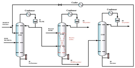
Figure 4.
The configuration of the TCERD process.
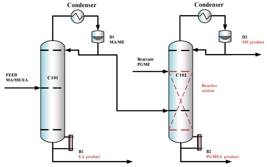
Figure 5.
The configuration of the DCPSRD process.
The DCPSRD process comprises two distillation columns: a pre-separation column and a reactive distillation column. The fresh feed flows into the pre-separation column C101, and is separated into the EA product and the MA/ME. The separation sequence of the reaction distillation column C102 is similar to that of the TCERD process.
2.2.2. Proposed RD-Based Processes
The previous designs [15] did not explore the option of withdrawing a product via a side stream in the extractive column, which may reduce entrainer flow, lower column height, and reboiler duty. The separation sequence is shown in Figure 6. To explore this option and its potential benefits under the new feed composition, an improved triple-column extractive–reactive distillation process with a side-draw product (TCERD-SP) is proposed, as shown in Figure 7, in which EA is obtained from the middle position of the C101 column with a side stream and a side reboiler. In the new TCERD-SP process, the upper part of the C101 column shows the pre-separation function of MA/ME and EA. Only a small amount of EA in the top distillate enters the extractive distillation column C102. The lower half of the C101 column is the entrainer recovery section. As the feed conditions (MA/ME mixture) of the TCERD, DCPSRD, and TCERD-SP processes entering the reactive distillation column are close, the reaction distillation columns in the three processes are basically similar.
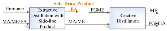
Figure 6.
Separation sequence of the MA transesterification reaction with EA as a side-draw product.
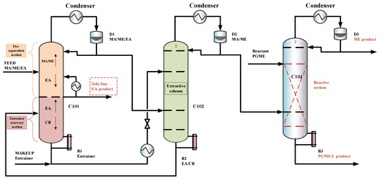
Figure 7.
The configuration of the TCERD-SP process.
2.3. Process Optimization
Following the conceptual design, in this study, an optimization method of parallel genetic algorithm (GA) is adopted from our previous work [19]. This optimization belongs to the category of mixed integer nonlinear programming (MINLP). The objective function is the TAC. The discrete design variables include total number of stages and the feed-stage location. The continuous design variables include distillate flowrates, reflux ratios, column pressures, solvent flowrate, and PGME flowrate. For the TCERD-SP process, four additional design variables, the side-draw location, the side-reboiler duty, pumparound, and side-draw flowrates are involved. The variable types (integer or continuous), bounds, and the optimal values are provided in the Supporting Information Tables S3–S5. The parallel GA uses a master–slave architecture, in which the central processing unit (master processor) executes the genetic operations of selection, crossover, and mutation, while the fitness functions are evaluated by slave processors. This master–slave architecture can be easily implemented and has the same search space as that of the serial GA [26], which is the advantage of parallel GA. MATLAB (R2024b) is interfaced with Aspen Plus via COM technology to enable distillation process optimization with parallel GA. The flowchart of MATLAB-Aspen Plus integrated parallel optimization is shown in Figure 8. The role of MATLAB is the optimization platform, in which the parallel GA generates candidate design variable sets. Each design variable set is written to Aspen Plus to conduct a steady-state simulation. The simulation results (such as the composition of products, equipment sizes, and heat duties) are passed back to MATLAB. For the parameters that meet the design specifications of product purity, the fitness functions of TAC are computed. Then, the parallel GA executes the evolutionary operators, and new populations are generated and written to Aspen Plus for iterative simulation. This iteration continues until the stop criteria of parallel GA are met. The setting parameters for the parallel GA are provided in Table 1. The optimization process stops as soon as the genetic algorithm meets either of two stopping criteria, reaching the maximum number of generations (600 in this study) or satisfying a function tolerance (1 × 10⁻⁵) over a specified number of stall generations (100). The optimization is performed on a desktop computer with an Intel Core i9 processor 14900KF (3.2 GHz) and 64 GB of RAM, and eight performance cores are utilized as slave processors, corresponding to eight parallel Aspen Plus instances.
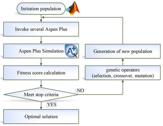
Figure 8.
Flowchart of MATLAB-Aspen Plus integrated parallel GA optimization.

Table 1.
The setting parameters of the parallel GA.
For the reactive distillation column, the tray holdup volume largely determines the column diameter (ID). In this work, the reactive holdup of catalyst in the reactive distillation column is assumed to be one-quarter of the tray holdup volume, with a weir height of 4 inches (0.1016 m) and a 90% active area [15,27]. The design procedure for determining the reactive holdup volume is iterative. Iterations continue until the difference between the column diameter from the last iteration and the current iteration is less than a specified tolerance (i.e., 0.001 m).
2.4. Economic and Environmental Performance Evaluation Index
In this work, to compare the performance of different processes, TAC is introduced as the metric to evaluate the processes’ economic performance. TAC comprises the total energy cost (TEC), including the cost for steam, cooling water, and related utilities, and the total capital cost (TCC) of major equipment (e.g., columns and heat exchangers). TCC is estimated using the Douglas correlations [28], with utility prices taken from Ref. [8]. A minimum temperature approach of 20 K is enforced between the reboiler and the heating steam. As all schemes use the same catalyst and reaction system, the catalyst cost and its recovery cost are ignored based on the reasonable assumption that the cost is similar [15]. In addition, to enable consistent comparison across different works, the assumptions and calculation procedures for TAC are consistent with those of Zhu et al. [15]. The payback period is assumed as 3 years, the operating hours is set to 8000 h, and the value of the Marshall and Swift index (M&S) in 2018 is assumed as 1638.2 [15,19]. The other detailed parameters are provided in the Supporting Information Table S6 [28,29]. Note that accurate and practical economic assessments require more accurate engineering design parameters.
CO2 emission (ECO2) is employed as the environmental performance evaluation index, and is evaluated with the Aspen Plus Carbon Tracking module [30,31], which combines process energy consumption with the CO2 emission factors of the fuel source to estimate total CO2 emissions of processes. In this study, natural gas is assumed as the fuel source, and the corresponding emission factors are sourced from the US-EPA Rule E9-5711 (CO2 E-US) [19].
3. Results and Discussion
3.1. Results of Process Optimization
In this section, the optimization results and optimal flowsheets of two existing RD-based processes and the proposed TCERD-SP process are presented. Figure S1a–c gives the optimization results of TCERD, DCPSRD, and TCERD-SP, respectively. The optimization procedure terminates when the genetic algorithm satisfies the stopping criteria, either the maximum number of generations is reached, or a specified function tolerance is achieved over a set number of stall generations. All of these process optimizations meet the latter stopping condition. The optimal TACs of three processes, TCERD, DCPSRD, and TCERD-SP, are USD 1,572,050, USD 1,682,799, and USD 1,440,114, respectively.
Figure 9 shows the optimal flowsheet of the TCERD process, in which the three columns C101, C102, and C103 contain 51, 44, and 21 trays, and operate at pressures of 1.0 atm, 3.084 atm, and 1.0 atm, respectively. The fresh feed enters the 28th stage of the extractive distillation column C101, and the top distillate stream from C101 containing the MA/ME mixture enters the 34th stage of the reactive distillation column C102. In addition, a PGME reactant stream with a flow rate of 25.055 kmol/h enters the 11th stage of C102, and then the ME product and PGMEA product are achieved in C102. The C101 bottom stream with EA and the entrainer CB enters the 10th stage of C103, in which the EA product is obtained from the distillate, and the CB is recovered and flows back to C101.
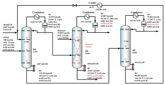
Figure 9.
The optimal flowsheet of the TCERD process.
The optimal flowsheet of the DCPSRD process is given in Figure 10. C101 is a pre-separation column, and C102 is a reactive distillation column which contains 57 and 51 trays, and operates at pressures of 3.204 atm and 4.434 atm, respectively. The overhead distillate from C101, which contains the MA/ME mixture, is fed to the reactive distillation column C102, where it contacts a pure PGME stream (24.765 kmol/h). Then, PGMEA is achieved as the bottom product, and ME is obtained as the distillate product.
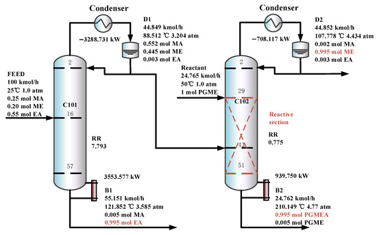
Figure 10.
The optimal flowsheet of the DCPSRD process.
Figure 11 shows the optimal flowsheet of the TCERD-SP process, in which the total number of trays of column C101 with a side-draw product stream, extractive distillation column (C102), and reactive distillation column (C103) are 52, 43, and 43, respectively. The operating pressures of the three columns are 1.0 atm, 1.0 atm, and 3.543 atm, respectively. The fresh feed and the recycled mixture of CB and EA are fed to the extractive distillation column C101 at the 7th stage and 38th stage, respectively. The EA product is obtained in the side-draw stream at the 22nd stage of C101. Both the overhead and bottom outlet streams from C101 are subsequently fed to C102. The overhead distillate from C101 contains MA, ME, and a small amount of EA; the bottom stream primarily contains the entrainer CB (36.790 kmol/h). In C102, component EA carried by the distillate of C101 is separated by extractive distillation and flows back to C101. The overhead stream from C102, containing MA and ME, is sent to the reactive distillation column C103 at the 34th stage, and a pure PGME stream (25.039 kmol/h) is fed into C103 at the 9th stage. Then, in the reactive distillation column C103, ME and PGMEA are achieved as the distillate product and bottom product, respectively. The distribution diagram of liquid phase composition in column C101 of the TCERD-SP process is shown in Figure 12. The upper section of C101 provides pre-separation of MA/ME and EA; a small amount of EA flows into C102 with the top distillate. The lower section serves as an entrainer-recovery zone, which is consistent with the conceptual design analysis of Figure 7.
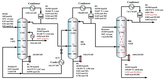
Figure 11.
The optimal flowsheets of the TCERD-SP process.
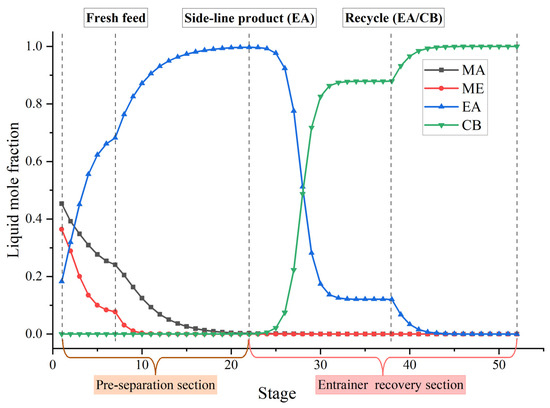
Figure 12.
Distribution diagram of liquid phase composition in column C101 of the TCERD-SP process.
Furthermore, in the TCERD-SP process, the EA product is withdrawn from an intermediate stage of C101 via a side stream, which lowers the operating temperature of the side reboiler. As a result, the side reboiler duty is 1016.361 kW (81.24 °C), and the condenser duty of the reactive distillation column C103 is −747.178 kW (100.578 °C). The temperature difference of the economizer is 19.338 °C. Compared with the existing processes, the heat integration between the side reboiler of C101 and the condenser (100.578 °C) of the reactive distillation column C103 can be conveniently introduced to enhance the process. The heat-integrated TCERD-SP process is denoted as TCERD-SP-HI and shown in Figure 13. The side auxiliary reboiler of C101 operates with a duty of 269.183 kW. Although the heat integration increases some capital cost relative to the TCERD-SP process, the TAC of the TCERD-SP-HI process is reduced to USD 1,285,813. The detailed parameters of the above four processes are provided in Table 2.
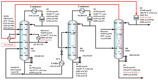
Figure 13.
The optimal flowsheet of the TCERD-SP-HI process.
Table 2.
The detailed process parameters of the TCERD, DCPSRD, TCERD-SP, and TCERD-SP-HI processes.
3.2. Discussion
As illustrated in Figure 14, the economic performance of the TCERD and DCPSRD processes exhibits opposite trends when the feed composition shifts from the prior feed composition (0.4MA/0.2ME/0.4EA) to the EA-rich feed (0.25MA/0.2ME/0.55EA) examined in this work. For the reactive distillation column, the MA-PGME transesterification reaction adopted in this study is endothermic, ΔH = +41.265 kJ/mol [12]. The reduction of reactant MA (0.40 to 0.25, −37.5%) and the corresponding reduction of reactant PGME lowers reboiler and condenser duties of the reactive distillation column. The influence of MA feed composition changes is consistent for both the TCERD and DCPSRD processes. Therefore, the difference in economic performance between the TCERD and DCPSRD processes is mainly due to the separation of EA and MA/ME.
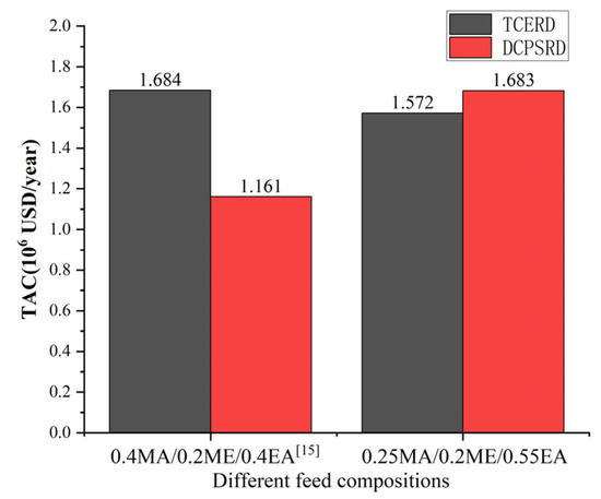
Figure 14.
Comparison of TAC performance of TCERD and DCPSRD processes at different feed compositions [15].
The opposite changes in the economic performances can be primarily attributed to the thermodynamic shifts caused by the change in feed composition. Based on the component balance, the composition points of the feed, the distillate, and the bottom product should be on a straight line, as shown in the ternary phase diagram in Figure 15. For a determined feed composition, as the composition point of the bottom product EA is fixed, the distillate composition point is determined by the specification of product purity. For the pre-separation column C101 in the DCPSRD process (Figure 10), the impurity EA in the distillate should be kept within a very small range to maintain the product purity in the subsequent reactive distillation. Therefore, for this EA-rich feed, the operating pressure of C101 should be increased to ensure that the distillate composition (Point A) lies near the MA/ME azeotrope with very few impurities EA rather than lying on the distillation boundary at atmospheric pressure (Point B). That is, the operating pressure of C101 in the DCPSRD process is affected by feed composition. However, the increase in operating pressure raises the reboiler temperature and heat duties of C101, and a higher reflux ratio is required to suppress EA in the distillate. Then, the reboiler and condenser duties are raised from 1455.41 kW [15] to 3553.58 kW and from 1362.82 kW [15] to 3288.73 kW, respectively. Correspondingly, the TAC of the DCPSRD process is increased with this EA-rich feed. Meanwhile, for the TCERD process, the heat duties of the extractive column (C101) and entrainer-recovery column (C103) rise only slightly, and TAC decreases from USD 1.684 × 10⁶ [15] to USD 1.572 × 10⁶ (Figure 14).
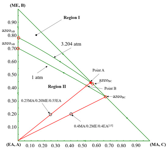
Figure 15.
The ternary diagram of MA/ME/EA at 1 atm and 3.2 atm [15].
Among the three RD-based processes without heat integration, the proposed TCERD-SP process exhibits superior performance under this EA-rich feed condition, as shown in Figure 16. Compared to the TCERD and DCPSRD processes, the TCERD-SP process can achieve 8.4% and 14.4% TAC savings, and reduce ECO2 by 14.5% and 27.4%, respectively. Note that the ECO2 is calculated using Aspen Carbon Tracking with fixed emission factors. Under these assumptions, ECO2 is approximately proportional to total heat duty. Thus, the reported ECO2 reductions mainly reflect reduced steam consumption of the TAC-optimized designs. In addition, compared to the TCERD-SP process, the TCERD-SP-HI process with heat integration can further reduce TAC by 10.7%, to USD 1,285,813. The proposed TCERD-SP and TCERD-SP-HI processes have good TAC advantages for this EA-rich feed composition.
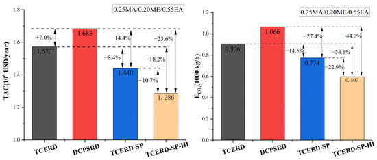
Figure 16.
Comparison of TAC and ECO2 performance of four processes.
The reason is that as the feed conditions entering the reactive distillation column are close, the heat duties of the reactive distillation column in the TCERD, DCPSRD, and TCERD-SP processes have no obvious differences. So, the TAC advantage of the TCERD-SP process is mainly attributed to the savings of the separation part of MA/ME and EA. And, lower energy demand reduces the corresponding ECO2 reduction under the adopted emission factors. In the proposed TCERD-SP process, the C101 column is partitioned by a side-draw stream into two sections (Figure 11 and Figure 12). The upper section pre-separates MA/ME from EA. Only a small amount of EA remains in the top distillate entering the extractive distillation column C102. Accordingly, a smaller amount of entrainer is required in C102, and the reboiler duty of C102 is reduced. The lower half of the C101 column serves as entrainer recovery, and less reboiler duty is needed at the C101 bottom. Furthermore, EA is obtained from the middle position of the column with a side reboiler. This arrangement lowers the side-reboiler temperature and energy use. Therefore, as shown in Table 2 for the separation of MA/ME and EA, the reboiler duties of the TCERD, DCPSRD, and TCERD-SP processes are 2762.300 kW (the reboiler duty of C101 and C103), 3553.577 kW (the reboiler duty of C101), and 2259.736 kW (the reboiler duty of C101 and C102), respectively. Compared with the TCERD and DCPSRD processes, the TCERD-SP process can achieve 18.2% and 36.4% reboiler duty savings, respectively. These indicate that, for this EA-rich feed condition, the arrangement of the side-draw and side reboiler of the TCERD-SP process can well improve the efficiency over the existing designs.
4. Conclusions
For an EA-rich feed (0.25MA/0.2ME/0.55EA), the previously optimal DCPSRD process requires elevated operating pressure in its pre-separation column, leading to significantly increased energy costs and diminished competitiveness. To address this challenge, a modified TCERD configuration incorporating a side-draw product (TCERD-SP) is proposed and optimized. The key modification in the TCERD-SP process is the strategic integration of a side-draw in the first column (C101) to withdraw the EA product. This arrangement reconfigures C101 into a combined pre-separation and entrainer-recovery unit within a single column. This design lowers the entrainer requirement and reboiler duty for the separation of EA from the MA/ME. Through parallel GA optimization, for the specified feed, the TCERD-SP process achieves 8.4% and 14.4% TAC savings versus the TCERD and DCPSRD processes, respectively. Moreover, the lowered temperature of the side reboiler in TCERD-SP enables convenient and effective heat integration with the condenser of the reactive distillation column, yielding a further-improved variant (TCERD-SP-HI) that achieves an additional 10.7% reduction in TAC. In summary, this study demonstrates the importance of considering feed composition in the design of hybrid RD processes. For this EA-rich feed examined in this work, the TCERD-SP and TCERD-SP-HI processes are demonstrated as effective solutions for recovering these valuable chemicals.
Supplementary Materials
The following supporting information can be downloaded at https://www.mdpi.com/article/10.3390/separations13010007/s1. Figure S1: The optimization results of three processes, (a) TCERD, (b) DCPSRD, and (c) TCERD-SP; Figure S2: T-xy diagram for MA-ME (1 atm); Figure S3: T-xy diagram for MA-EA (1 atm); Figure S4: T-xy diagram for ME-EA (1 atm); Figure S5: T-xy diagram for EA-CB (1 atm); Figure S6: T-xy diagram for ME-CB (1 atm); Figure S7: T-xy diagram for PGME-PGMEA (1 atm); Figure S8: T-xy diagram for MA-PGME (1 atm); Figure S9: T-xy diagram for ME-PGMEA (1 atm); Figure S10: T-xy diagram for MA-PGMEA (1 atm). Table S1: The binary parameters of NRTL model; Table S2: The kinetic parameters of the MA-PGME transesterification reaction; Table S3: The optimization decision variables of the TCERD process; Table S4: The optimization decision variables of the DCPSRD process; Table S5: The optimization decision variables of the TCERD-SP process; Table S6. The method to estimate TAC [12,18,20,21,22,23,24,25,28,29].
Author Contributions
Investigation, W.X.; data curation, L.W. and K.L.; writing—original draft, C.J.; writing—review and editing, C.J. All authors have read and agreed to the published version of the manuscript.
Funding
This research was funded by the Science and Technology Plan Project of Jiaxing city in China (No. 2025CGZ017), National College Students Innovation and Entrepreneurship Training Program (No. 202413291007), and University–Industry Collaborative Education Program (No. 240903053244613).
Data Availability Statement
The original contributions presented in this study are included in the article/Supplementary Materials. Further inquiries can be directed to the corresponding author.
Conflicts of Interest
The authors declare that they have no known competing financial interests or personal relationships that could have appeared to influence the work reported in this paper.
Nomenclature
| AD | Azeotropic distillation | NT | Total number of stages |
| CB | Chlorobenzene | NF | Feed location |
| DCPSRD | Double-column pre-separation-reactive distillation | Nside-draw | Side-draw location |
| EA | Ethyl acetate | PGME | Propylene glycol monomethyl ether |
| ECO2 | CO2 emission | PGMEA | Propylene glycol monomethyl ether acetate |
| ED | Extractive distillation | PSD | Pressure-swing distillation |
| EO | Ethylene oxide | QR | Reboiler duty |
| FD | Flowrate of distillate | RD | Reactive distillation |
| Fentrainer | Flowrate of entrainer | RR | Reflux ratio |
| FPGME | Flowrate of reactant PGME | TAC | Total annual cost |
| Fside-draw | Flowrate of side-draw | TCC | Total capital cost |
| Fside-line reflux | Flowrate of side-line reflux | TCERD | Tripe-column extractive–reactive distillation |
| GA | Genetic algorithm | TCERD-SP | Triple-column extractive–reactive distillation with a side-draw product |
| MA | Methyl acetate | TCERD-SP-HI | Triple-column extractive–reactive distillation with a side-draw product and heat-integration |
| ME | Methanol | TCRED | Triple-column reactive–extractive distillation |
| MINLP | Mixed integer nonlinear programming | TEC | Total energy costs |
| M&S | Marshall and Swift index | ID | Column diameter |
References
- Tavan, Y.; Hosseini, S.H. A novel integrated process to break the ethanol/water azeotrope using reactive distillation—Part I: Parametric study. Sep. Purif. Technol. 2013, 118, 455–462. [Google Scholar] [CrossRef]
- Li, C.; Zhang, J.; Rao, J.; Shi, K.; Sun, Y.; Liu, W.; Liu, J. Vapor Liquid Equilibrium Measurement and Distillation Simulation for Azeotropic Distillation Separation of H2O/EM Azeotrope. Separations 2025, 12, 273. [Google Scholar] [CrossRef]
- Gao, M.; Zhang, Q.; Jin, Z.; Liu, Y.; Dai, Y. Economic; Environmental, and Safety Multi-Objective Optimization Design for Separation of Tetrahydrofuran/Methanol/Water Mixture. Separations 2025, 12, 255. [Google Scholar] [CrossRef]
- Sander, A.; Petračić, A.; Rogošić, M.; Župan, M.; Frljak, L.; Cvetnić, M. Feasibility of Different Methods for Separatingn-Hexane and Ethanol. Separations 2024, 11, 151. [Google Scholar] [CrossRef]
- Kiss, A.A.; Bildea, C.S. Reactive distillation: Stepping up to the next level of process intensification. Ind. Eng. Chem. Res. 2018, 57, 15811–15825. [Google Scholar] [CrossRef]
- Kong, Z.Y.; Sunarso, J.; Yang, A. Recent progress on hybrid reactive-extractive distillation for azeotropic separation: A short review. Front. Chem. Eng. 2022, 4, 986411. [Google Scholar] [CrossRef]
- Malone, M.F.; Doherty, M.F. Reactive distillation. Ind. Eng. Chem. Res. 2000, 39, 3953–3957. [Google Scholar] [CrossRef]
- Yang, A.; Su, Y.; Sun, S.; Shen, W.; Bai, M.; Ren, J. Towards sustainable separation of the ternary azeotropic mixture based on the intensified reactive-extractive distillation configurations and multi-objective particle swarm optimization. J. Clean. Prod. 2022, 332, 130116. [Google Scholar] [CrossRef]
- Huang, J.H.; Zhang, Q.; Liu, C.; Yin, T.; Xiang, W. Optimal design of a ternary azeotrope separation process assisted by reactive-extractive distillation for ethyl acetate/isopropanol/water. Sep. Purif. Technol. 2023, 307, 122941. [Google Scholar] [CrossRef]
- Su, Y.; Yang, A.; Jin, S.; Shen, W.; Cui, P.; Ren, J. Investigation on ternary system tetrahydrofuran/ethanol/water with three azeotropes separation via the combination of reactive and extractive distillation. J. Clean. Prod. 2020, 273, 123145. [Google Scholar] [CrossRef]
- Wang, C.; Zhuang, Y.; Liu, L.; Zhang, L.; Du, J. Design and comparison of energy-saving double-column and triple-column reactive-extractive hybrid distillation processes for ternary multi-azeotrope dehydration. Sep. Purif. Technol. 2021, 259, 118211. [Google Scholar] [CrossRef]
- Wang, X.; Wang, Q.; Ye, C.; Dong, X.; Qiu, T. Feasibility study of reactive distillation for the production of propylene glycol monomethyl ether acetate through transesterification. Ind. Eng. Chem. Res. 2017, 56, 7149–7159. [Google Scholar] [CrossRef]
- Chaniago, Y.D.; Hussain, A.; Andika, R.; Lee, M. Reactive pressure-swing distillation toward sustainable process of novel continuous ultra-high-purity electronic-grade propylene glycol monomethyl ether acetate manufacture. ACS Sustain. Chem. Eng. 2019, 7, 18677–18689. [Google Scholar] [CrossRef]
- Chaniago, Y.D.; Naquash, A.; Nhien, L.C.; Naquash, A.; Riaz, A.; Kim, G.S.; Lim, H.; Lee, M. Pressure swing-based reactive distillation and dividing wall column for improving manufacture of propylene glycol monomethyl ether acetate. Energies 2021, 14, 7416. [Google Scholar] [CrossRef]
- Zhu, J.; Lin, H.; Zhu, Z.; Wei, H. Development of novel hybrid pre-separation/extractive reactive distillation processes for the separation of methanol/methyl acetate/ethyl acetate. Sep. Purif. Technol. 2024, 348, 127496. [Google Scholar] [CrossRef]
- Renon, H.; Prausnitz, J.M. Local compositions in thermodynamic excess functions for liquid mixtures. AIChE J. 1968, 14, 135–144. [Google Scholar] [CrossRef]
- Wang, C.; Zhuang, Y.; Qin, Y.; Dong, Y.; Liu, L.; Zhang, L.; Du, J. Optimization and ecoefficiency analysis of extractive distillation processes with different solvents for separating the ternary mixture embedding two azeotropes. Sep. Purif. Technol. 2021, 269, 118763. [Google Scholar] [CrossRef]
- Hussain, A.; Chaniago, Y.D.; Riaz, A.; Lee, M. Process design alternatives for producing ultra-high-purity electronic-grade propylene glycol monomethyl ether acetate. Ind. Eng. Chem. Res. 2019, 58, 2246–2257. [Google Scholar] [CrossRef]
- Jing, C.; Liao, L.; Yang, H. Process design, intensification and control of triple-column pressure-swing distillation for the separation of methyl acetate/methanol/ethyl acetate. Sep. Purif. Technol. 2025, 361, 131361. [Google Scholar] [CrossRef]
- Cao, J.; Yu, G.; Chen, X.; Abdeltawab, A.A.; Al-Enizi, A.M. Determination of vapor liquid equilibrium of methyl acetate + methanol + 1-alkyl-3-methylimidazolium dialkylphosphates at 101.3 kPa. J. Chem. Eng. Data. 2017, 62, 816–824. [Google Scholar] [CrossRef]
- Nishi, Y. Vapor-liquid equilibria accompanied by hypothetical chemical reaction. J. Chem. Eng. Jpn. 1972, 5, 334–339. [Google Scholar] [CrossRef]
- Zhang, X.; Liu, H.; Liu, Y.; Jian, C.; Wang, W. Experimental isobaric vapor-liquid equilibrium for the binary and ternary systems with methanol, methyl acetate and dimethyl sulfoxide at 101.3 kPa. Fluid Phase Equilib. 2016, 408, 52–57. [Google Scholar] [CrossRef]
- Reddy, B.S.; Rao, B.V.S. Isoharic vapour-liquid equilibrium data of ethyl acetatechlorobenzene and toluene-n-butyl acetate mixtures at 101.3 kPa pressure. Indian Chem. Eng. 1988, 30, 50–52. [Google Scholar]
- Feng, Y.; Mao, S. Vapor-liquid equilibria for binary systems of methanol-chlorobenzene and chlorobenzene-dimethyl sulfoxide. J. Chem. Eng. Chinese Univ. 1991, 5, 73–78. [Google Scholar]
- Ye, C.; Dong, X.; Zhu, W.; Cai, D.; Qiu, T. Isobaric vapor-liquid equilibria of the binary mixtures propylene glycol methyl ether + propylene glycol methyl ether acetate, methyl acetate + propylene glycol methyl ether and methanol + propylene glycol methyl ether acetate at 101.3 kPa. Fluid Phase Equilib. 2014, 367, 45–50. [Google Scholar] [CrossRef]
- Cantú-Paz, E.; Goldberg, D.E. Efficient parallel genetic algorithms: Theory and practice. Comput. Methods Appl. Mech. Eng. 2000, 186, 221–238. [Google Scholar] [CrossRef]
- Wu, T.-W.; Chien, I.L. CO2 utilization feasibility study: Dimethyl carbonate direct synthesis process with dehydration reactive distillation. Ind. Eng. Chem. Res. 2020, 59, 1234–1248. [Google Scholar] [CrossRef]
- Douglas, J. Conceptual Design of Chemical Processes; McGraw-Hill: New York, NY, USA, 1988. [Google Scholar]
- Turton, R.; Bailie, R.C.; Whiting, W.B.; Shaeiwitz, J.A. Analysis, Synthesis and Design of Chemical Processes, 2nd ed.; Prentice Hall: Englewood Cliffs, NJ, USA, 2003. [Google Scholar]
- Zhu, J.; Huang, J.; Zhao, X.; Hao, L.; Yang, A.; Shen, W. Energy-Efficient Extractive Pressure-Swing Distillation with Integrated Preconcentration Column and Natural Decanter for Ternary Heterogeneous Mixtures. Energy 2025, 337, 138602. [Google Scholar] [CrossRef]
- Zhu, J.; Chen, L.; Liu, Z.; Hao, L.; Wei, H. Synergy of electrification and energy efficiency improvement via vapor recompression heat pump and heat exchanger network to achieve decarbonization of extractive distillation. Sep. Purif. Technol. 2022, 293, 121065. [Google Scholar] [CrossRef]


Disclaimer/Publisher’s Note: The statements, opinions and data contained in all publications are solely those of the individual author(s) and contributor(s) and not of MDPI and/or the editor(s). MDPI and/or the editor(s) disclaim responsibility for any injury to people or property resulting from any ideas, methods, instructions or products referred to in the content. |
© 2025 by the authors. Licensee MDPI, Basel, Switzerland. This article is an open access article distributed under the terms and conditions of the Creative Commons Attribution (CC BY) license.