Abstract
Silicon carbide (SiC) three-phase converters are widely adopted in parallel power distribution systems for their high efficiency, yet their performance is challenged by high switching frequency and communication constraints. For the parallel inverter system, problems such as uneven power distribution and circulating current may occur. Therefore, the droop control method was proposed. The droop control method is limited in precise power sharing and circulating current mitigation. To address these issues in the communication-free parallel inverter system, a hybrid droop-enhanced virtual impedance method is proposed. The methodology integrates droop characteristics with frequency-selective virtual impedance compensation, enabling concurrent optimization of power sharing and circulating current suppression. Through simulation, the droop control method and the improved droop control method were compared and analyzed. Finally, the effectiveness of the improved droop control method was verified through experiments.
1. Introduction
By comparing the processes and device simulations of SiC MOSFETs and Si MOSFETs, it is shown that the SiC MOSFET has performance advantages in terms of voltage drop and on-resistance. The SPICE simulation indicates that the small increment in the on-resistance of the SiC device is very crucial, as it can significantly improve the performance [1]. As shown in Table 1, the SiC MOSFET we adopted has comprehensively outperformed the traditional Si IGBT in key performance indicators such as switching frequency, turn-on speed, power density, and switching loss.

Table 1.
Comparison of performance parameters between SiC MOSFET and Si MOSFET.
The parallel operation of silicon carbide (SiC) three-phase inverters has emerged as a critical enabler for scaling power capacity in low-voltage microgrids, addressing the inherent limitations of single-module systems in renewable energy integration [2,3]. However, the high-frequency switching dynamic characteristics of silicon carbide devices intensify circulating currents, primarily composed of fundamental and fifth/seventh harmonic components, which account for over 15% of rated current amplitudes under unbalanced load conditions. These currents induce substantial switching losses and efficiency degradation, posing formidable challenges to system stability [4]. The conventional control frameworks designed for silicon-based converters fail to accommodate the rapid transient response of SiC-based systems, necessitating advanced power-sharing mechanisms tailored to high-frequency operating regimes.
Therefore, the parallel converters require a clear power-sharing mechanism to ensure that power and thermal stress are evenly distributed between modules and to prevent one or more modules from operating in power-limiting mode. There are many power-sharing methods, such as the droop method, dedicated master–slave current planning, automatic control average current planning, automatic control maximum current planning, and external control. However, existing power-sharing strategies exhibit three principal limitations. Master–slave architectures, while achieving ±1% current accuracy, suffer from communication latency and single-point failure risks, rendering them unsuitable for mission-critical applications [5]. Droop control, though communication-free, incurs >5% power-sharing errors due to fixed droop coefficients and neglects circulating currents induced by port voltage discrepancies. Virtual impedance compensation methods, such as those employing rotating-frame circulating current components [6], mitigate line impedance mismatches without real-time monitoring but introduce >3% voltage deviations from PI control delays. In addition, an automatic current-sharing method based on fuzzy logic control for the current-sharing circuit has also been proposed [7].
With the increase in the number of inverter modules in parallel, the stability is also at risk. Among them, the circulation current is particularly prominent. The essence of the circulation current is the energy flow caused by the uneven power distribution of multiple inverters. Uneven voltage distribution leads to the generation of circulating current. This circulating current inherently contains high-order harmonic components. At the same time, it may cause phenomena such as current limit “peaking” and filter inductor saturation, indirectly generating new low-order harmonics or high-order harmonics, thereby increasing the total harmonic distortion of the three-phase current. Even worse, it may damage the power supply equipment at present, as the suppression methods of fundamental circulation mainly focus on improving the power distribution among converters in parallel systems. Ref. [8] discusses the definition and characteristics of circulating current in parallel inverter systems. Therefore, the suppression of circulating currents hinges on precise power distribution and impedance matching across paralleled modules. However, idealized inverter models neglect harmonic coupling effects from SiC’s high-frequency switching, causing a more severe power imbalance phenomenon. Ref. [9] proposes the method of utilizing the current difference between parallel inverters, but the control efficiency of this method is very low at a low modulation ratio. A nonlinear control method is proposed in the literature [10,11], but the method is very complicated and not suitable for practical application. In [12], the amplitude and phase of the output voltage are adjusted by the active circulation power and reactive circulation power to achieve the control objectives of circulation suppression and load equalization during parallel operation.
To effectively achieve power balancing, ref. [13] reduces the difference in line impedance by adding virtual impedance to the output line impedance of the inverter, thereby improving the accuracy of reactive power balancing. The adaptive virtual complex impedance was introduced in [14], and the virtual complex impedance was mentioned in [15]. By using the virtual impedance, power decoupling and reasonable reactive power distribution can be achieved. The negative resistance part of the virtual impedance reduces the resistive component of the line, while the inductive part of the virtual impedance increases the inductive component of the system, weakens the coupling degree of power, and improves the accuracy of power distribution and the effect of circulating current suppression, which is mentioned in [16]. The cyclic suppression and power balance control strategies were mainly studied, and a multi-loop control strategy including a virtual negative inductive reactance component and an adaptive virtual impedance was proposed in [17]. The difference between the real-time power and the ideal power is introduced into the virtual impedance, thereby adaptively adjusting the impedance size to achieve cyclic current suppression, as mentioned in [18], but it relies on the communication system. The introduction of virtual impedance effectively achieves power decoupling and uniform distribution of reactive power and effectively suppresses the situations of circulating current and heterogeneous current. However, virtual impedance can only effectively solve the problem of reactive power sharing and has a poor effect on active power sharing.
In addition, the droop control method is also commonly used for parallel connection of inverters [19]. An adaptive droop coefficient adjustment method has been proposed to solve the contradiction between power distribution accuracy and dynamic response in traditional methods [20,21]. Improved droop also has been proposed, which can control the power-sharing error within 1.5% [22]. By analyzing the equivalent model of the parallel system, researchers used dynamic feedforward compensation technology to handle nonlinear load disturbances, and experiments showed that THD can be reduced to less than 2% [23]. In addition, by optimizing the droop coefficient and implementing parallel current-sharing control, distributed self-regulation of current balance is achieved [24]. By improving the power droop control strategy of the inverter, a higher power distribution accuracy and good dynamic response capability between parallel inverters were achieved, and the cyclic current between parallel inverters was suppressed, which was mentioned in [25]. The improved droop control method introduces virtual resistance and resistance in the equivalent output impedance of the inverter, making it a purely inductive load. However, the influence of excessive resistance on the system power and voltage drop was ignored, and at the same time, the influence of nonlinear loads on the harmonic stability of the system could not be eliminated. The problem of voltage distortion and unreasonable power distribution between parallel inverters caused by harmonic current passing through virtual resistance was mentioned in [26]. The vertical control strategy enables each distributed power source to effectively eliminate the voltage drop on the AC bus and restore the bus voltage to the rated value while achieving precise reactive power distribution, as proposed in [27].
The multi-module parallel system based on droop control does not rely on complex communication protocols, avoiding the risk of single-point failure. However, the droop control strategies exhibit degraded power-sharing accuracy under line impedance mismatches and lack active suppression mechanisms for harmonic circulating currents, resulting in elevated current stress, increased total harmonic distortion, and compromised system efficiency in parallel SiC inverter systems. There are still some new methods related to improving the quality of voltage and current. Taking the parallel inverter system as the research object, in response to the amplitude, frequency deviation, and power imbalance problems caused by the droop control in the distributed system, a quadratic control protocol is proposed, which simultaneously solves the problem of system voltage tracking and power synchronization [28]. Taking the parallel system of three-phase inverters as the research object, an improved droop control strategy based on adaptive virtual impedance is studied, aiming to achieve the reasonable distribution of inverter output power and improve the control performance of the system [29]. A detailed analysis of the circulating current model in the parallel photovoltaic inverter was conducted, and an effective centralized control strategy was proposed to suppress the circulating current. The article also includes a detailed harmonic analysis [30]. Comprehensive modeling and analysis of the circulating currents (including differential mode and common mode) in the parallel three-phase inverter were conducted, and different control methods were compared. The theoretical analysis was very rigorous [31]. Not only did it consider the control differences, but it also specifically analyzed the influence of the DC-side voltage ripple on the circulating current and proposed corresponding suppression strategies. It also conducted in-depth discussions on the harmonic components of the circulating current [32]. Although it is specifically about the modular multilevel converter, its analysis of the harmonic components in the circulating current and the suppression method based on repetitive control are of great significance for understanding and addressing the issues related to the circulating current of the system [33]. An earlier but very classic paper introduced how to suppress circulating currents in a parallel inverter system without interconnection lines (droop control) and analyzed the impact of circulating currents on the system performance [34]. These papers collectively form a complete knowledge system covering the generation mechanism of circulation, mathematical modeling, harmonic analysis, and advanced suppression strategies. They are the authoritative academic sources supporting the aforementioned arguments. Virtual impedance utilizes the characteristic relationship between voltage and current to add a virtual impedance in the control link, compensate for the line impedance, and, at the same time, reduce the degree of power coupling and reduce the circulating current. It will not introduce additional losses to the system, nor will it cause additional increases in the project cost or equipment volume [35]. A large number of articles indicate that droop control has a strong dependence on virtual impedance. If the performance of droop control needs to be improved, virtual impedance needs to be introduced under the droop control method. By enhancing the virtual impedance and droop control method, the line impedance is compensated, effectively suppressing power oscillations and enhancing the damping effect of the system. The parameters of the voltage and current dual-loop control are optimized, the current loop bandwidth is increased, and the current signal is accurately and quickly tracked, thereby improving the overall dynamic response. Based on the analysis of the above problems, this paper proposes a method to control the power sharing of multiple inverters based on the droop coefficient regulation, minimize the circulation current between the inverters, and then reduce the circulation current by increasing the virtual impedance to achieve the best optimization effect and minimize the circulation current. MATLAB/Simulink (MATLAB R2024a) simulates the three-phase parallel inverter system with the above control method and verifies that the droop control and virtual impedance proposed can improve the effect of restraining the circulation.
This article to combine virtual impedance with droop control while also integrating the advantages of both in the distribution of active and reactive power. We develop measurements of voltage, current THD, power, and circulating current under different switching frequencies, and conduct a comparative analysis. This article demonstrates that the improved droop control has certain advantages over the traditional single method in terms of power distribution and suppression of circulating current.
2. Analysis of Parallel Control Strategy for Inverters
In the parallel operation system of a three-phase converter, the output voltage of different inverter modules is different due to the mismatch of system impedance, so there is a circulation current and a power-sharing problem between the inverters. As shown in Figure 1, the inconsistency of output voltage is often because the parameters between different modules will not be completely consistent in actual conditions. When the system is started, the switching state between modules is inconsistent, and when the switching state is consistent but the module line impedance is not matched, it will lead to the generation of circulating current. And the arrows in the picture represent the direction of the current.
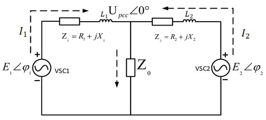
Figure 1.
Equivalent circuit of the parallel inverters.
When inverters are interconnected via a dual common bus configuration, the total load impedance is equivalent to the summation of output impedances from multiple inverters and the associated line impedance. The corresponding output currents and load currents are analytically expressed in (1)–(3).
When is not equal to , the circulation current is obtained, as shown in (4).
It can be seen from (4) that the elimination of circulating currents necessitates matching both the total impedance and the output voltage characteristics (amplitude and phase) between paralleled inverters. Consequently, augmenting virtual impedance to emulate the characteristics of physical resistance and inductance mitigates voltage disparities among paralleled power sources, thereby suppressing circulating currents through impedance-mediated voltage compensation.
In a parallel converter system, circulating current refers to the current that does not flow through the load or the power grid but instead circulates between the parallel units. The main factors causing circulating current are the parameter differences between the parallel units, mainly including differences in control signals, hardware parameters, and differences in the DC-side voltage. The circulating current itself can be decomposed into different frequency components. Among them, the harmonics near the switching frequency have the most direct impact on power quality, followed by causing total harmonic distortion, resulting in electromagnetic interference, increasing harmonic risks, and leading to neutral line current problems.
ma(t) represents the ideal modulation signal, and is the error voltage caused by parameter and control differences. To simplify the analysis, we assume that . The circulating current path Ih is VSC1—filter inductor —grid PCC—filter inductor —VSC2. Applying Kirchhoff’s voltage law to this circulating current loop gives:
Simplifying this gives:
Substituting this into Formulas (5) and (6) gives:
The error voltage includes the harmonic components resulting from the differences. In SPWM, the main harmonics are distributed near the switching frequency and its multiples. Assuming that mainly contains a harmonic component with an amplitude of and a frequency of (close to ), we get:
Then, the derivative of the circulation is proportional to this harmonic voltage:
Integrating over time, the circulation expression is obtained:
Ignoring the DC component , the amplitude of this harmonic component in the circulating current is:
Formula (13) is the core formula, which indicates that the error voltage between the converters will generate significant harmonic currents in the circulating current. To alleviate the aforementioned power quality issues, it is necessary to suppress the circulating current. Common methods for suppressing the circulating current include hardware methods and control methods, among which zero-sequence circulating current suppression is the most common.
As illustrated in Figure 2, a significant current-sharing imbalance was observed when paralleling inverters with mismatched line impedances without compensation. Inverter 1 delivered three-phase output currents with an amplitude of 16 A, while inverter 2 exhibited approximately 8 A. The post-switching measurements also revealed current imbalance, with inverter 1 generating 8 A output currents versus inverter 2’s 5 A. The THD analyses quantified substantial waveform distortions, showing individual voltage THD values of 3.24% and 3.25% for the two inverters, respectively. The current THD values are 1.08% and 1.04% for the two inverters, respectively.
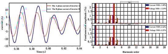
Figure 2.
The output currents wave (left) and the THD of the output voltage and current (right).
2.1. Virtual Impedance Control Method
In practical implementations, fixed system impedance cannot be arbitrarily adjusted, and impedance mismatches must be compensated through control-oriented solutions, necessitating the employment of virtual impedance techniques. The equivalent circuit after introducing virtual impedance to the two parallel inverters, where the virtual impedance, output impedance, and line impedance of the two can be expressed, is shown in Figure 3.
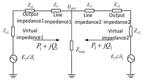
Figure 3.
Virtual impedance method equivalent circuit diagram.
The implementation of virtual impedance offers programmable flexibility: when the converter’s inherent output and line impedances are low, a dominant virtual impedance can be synthesized to govern the equivalent total impedance, while active compensation can be applied to existing impedance paths for multi-frequency domain optimization. As shown in Figure 4, virtual impedance governs the equivalent system impedance when designed to satisfy two critical criteria: (1) || ≫ ||, ensuring virtual impedance dominance over the inherent output and line impedances, and (2) || ≫ ||, which synthesizes a predominantly inductive equivalent impedance to fulfill the power decoupling condition. This configuration effectively aligns both the magnitude and phase characteristics of the converter’s total impedance with the virtual impedance parameters.
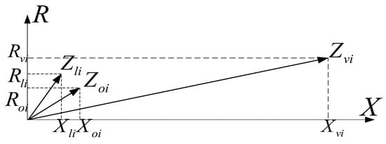
Figure 4.
Impedance vector diagram of the virtual impedance dominant system.
According to the equivalent circuit diagram in Figure 3 and by using Formulas (1)–(4) and the condition , the circulation current and power calculation is conducted as shown in (14)–(17).
Since >> , the active power and reactive power can be simplified to the Formulas (18) and (19).
The second inverter has the same principle as the first one, and the formula is the same as above.
The MATLAB/Simulink simulation results at a switching frequency of 10 kHz, as shown in Figure 5, reveal distinct performance characteristics of the virtual impedance method: while active power sharing exhibits suboptimal equalization, reactive power achieves near-ideal distribution with fully overlapping reactive power trajectories. Concurrently, the virtual impedance demonstrates effective circulating current suppression, constraining the maximum circulating current amplitude to 0.2 A under rated operating conditions. The RMS value is equal to the peak value. The RMS value is approximately 0.141.
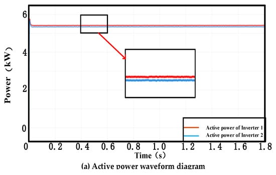
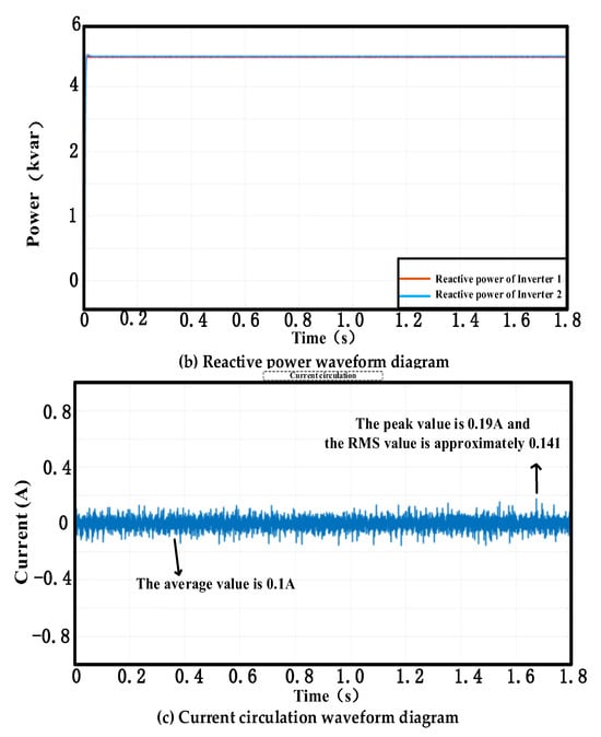
Figure 5.
The switching frequency is 10 kHz, and the parallel output of the inverter is realized by using the virtual impedance method. (a) Active power waveform diagram of the inverter 1, 2. (b) Reactive power waveform diagram of the inverter 1, 2. (c) Current circulation waveform diagram of the inverter.
Figure 6 presents the MATLAB/Simulink simulation results of the virtual impedance under a switching frequency of 100 kHz. Compared with the active power, reactive power, and circulating current phenomena of the virtual impedance under a switching frequency of 10 kHz in Figure 5, the results show that the reactive power equalization effect at a switching frequency of 100 kHz is not as good as that at 10 kHz. and the circulating current is within the range of 1 A. The RMS value is approximately 1.13.
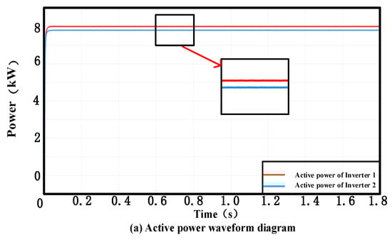
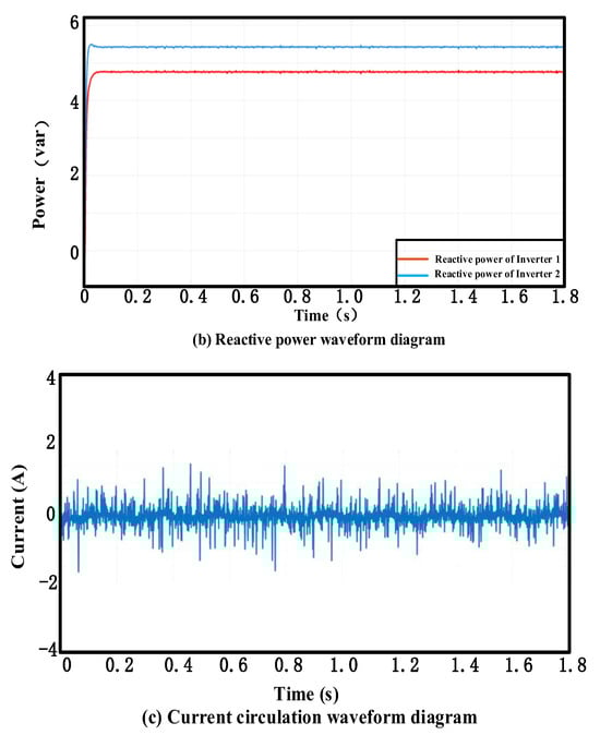
Figure 6.
The switching frequency is 100 kHz, and the parallel output of the inverter is realized by using the virtual impedance method. (a) Active power waveform diagram of the inverter 1, 2. (b) Reactive power waveform diagram of the inverter 1, 2. (c) Current circulation waveform diagram of the inverter.
2.2. Droop Control Method
Droop control provides a communication-free solution for decentralized active/reactive power sharing in parallel inverter systems by leveraging the inherent voltage-frequency droop characteristics, which facilitates plug-and-play expandability and reduced control complexity. However, this method inherently suffers from a fundamental compromise between power distribution accuracy and voltage regulation dynamics, along with heightened sensitivity to line impedance mismatches that provoke persistent circulating currents and degrade system stability margins under variable grid impedance conditions. The inherent limitations of droop control in achieving reactive power balance and exacerbating circulating currents primarily stem from four inter-related mechanisms.
Droop control theory assumes purely inductive line impedance, whereas practical low-voltage systems exhibit non-negligible resistive components. This impedance mismatch disrupts P-Q decoupling, inducing a 12–15% reactive power-sharing error, while impedance variance across inverters creates unequal voltage drops, generating circulating current excitation sources that amplify current disparities by 50% under 10% impedance mismatch. In addition, fixed droop coefficients, typically tuned for rated conditions, fail to adapt to real-time load or impedance changes. During light-load operations, minor reactive power deviations trigger voltage overshoots, provoking “reactive power hunting” between units. The delayed response of voltage-based reactive power regulation further aggravates transient circulating currents. Moreover, minor discrepancies in inverter equivalent output impedance disproportionately affect reactive power distribution. Circulating currents interact with line impedance to perturb output voltage phasors, forming a positive feedback loop.
Figure 7 presents MATLAB/Simulink simulation results quantifying the transient and steady-state performance of droop-controlled parallel inverters. When there is no signal synchronization setting and the line impedance is mismatched, the active power sharing under droop control exhibits significant transient oscillations during startup yet achieves steady-state convergence within 0.1 s from startup across units. Conversely, reactive power sharing fails to maintain stable equilibrium, showing an inter-unit discrepancy attributed to impedance mismatch effects. Circulating currents further validate these limitations.
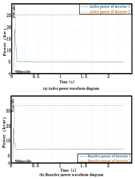
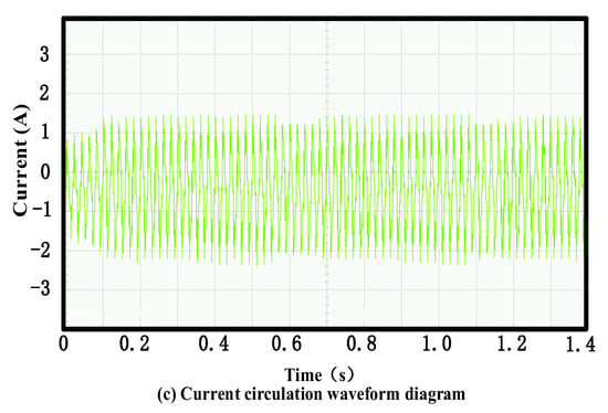
Figure 7.
The switching frequency is 10 kHz, and the parallel output of the inverter is realized by using the droop control method. (a) Active power waveform diagram of the inverter 1, 2. (b) Reactive power waveform diagram of the inverter 1, 2. (c) Current circulation waveform diagram of the inverter.
Figure 8 presents the MATLAB/Simulink simulation results of the droop control method under a switching frequency of 100 kHz. Compared with the active power, reactive power, and circulating current phenomena of the droop control method under a switching frequency of 10 kHz in Figure 7, when there is no signal synchronization setting and the line impedance is mismatched, the results show that the active power distribution effect is weakened and that the circulating current is within the range of 8 A. The RMS value is approximately 8.5.
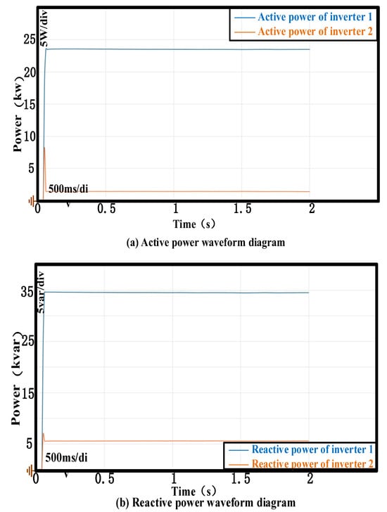
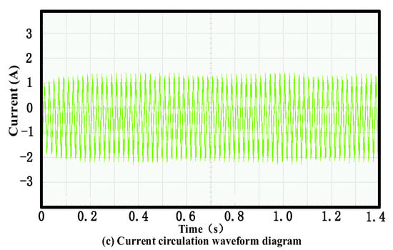
Figure 8.
The switching frequency is 100 kHz, and the parallel output of the inverter is realized by using the droop control method. (a) Active power waveform diagram of the inverter 1, 2. (b) Reactive power waveform diagram of the inverter 1, 2. (c) Current circulation waveform diagram of the inverter.
2.3. Improved Droop Control Method
This paper presents an improved droop control strategy, which addresses the power distribution imbalance problem caused by communication delay in the droop method. The control system of the improved droop necessitates systematic decoupling of cross-coupled terms inherent in the inverter topology. As shown in Figure 9a, the MATLAB simulation models the outer voltage loop and the inner current loop. The voltage loop and the current loop, respectively, use PI controllers, and then the PWM control signal is obtained through transformation. As shown in Figure 9b, a dual-loop control architecture is implemented, where decoupling compensation terms are integrated into both the capacitor voltage feedback loop and inductor current feedback loop. The -axis capacitor voltages are regulated via PI controller , with reference values generated from the droop equation. The compensated voltage output combines the PI-regulated signal and decoupling terms to establish the inductor current references. The dq-axis inductor currents are tracked by PI controller . The resultant modulated waveform integrates both current feedback and dynamic decoupling compensation.
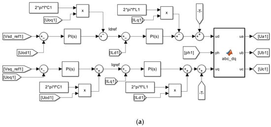
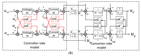
Figure 9.
(a) MATLAB/Simulink control model. (b) Mathematical model of the inverter with decoupled terms.
The integrated controller-converter model yields a frequency-domain control block diagram of the power converter. By embedding a virtual impedance compensation loop into the baseline dual-loop architecture (inner current loop + outer voltage loop), the enhanced control structure shown in Figure 10 is derived, where the virtual impedance branch actively reshapes the equivalent output impedance characteristics to suppress low-frequency circulating currents under impedance-mismatched conditions.
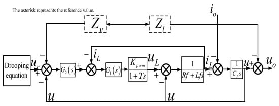
Figure 10.
Inverter control block diagram with virtual impedance control loop.
Figure 11 shows the parallel circuit diagram of the three-phase inverter in MATLAB/Simulink, so all methods are carried out based on this diagram.
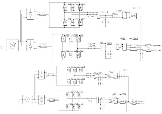
Figure 11.
Parallel inverter connection mode with MATLAB/Simulink.
From the block diagram in Figure 10, the converter output voltage is derived as (20):
where , , , and , respectively, represent the converter output voltage, output current, reference voltage, and reference voltage gain coefficient, and , , and , respectively, represent the virtual impedance, output impedance, and line impedance, where .
The expression for the virtual impedance can be expressed as (21):
The virtual impedance is designed as (6), where the virtual resistance introduces critical stability–power decoupling tradeoffs. A positive Rv enhances low-frequency stability by imposing resistive characteristics but degrades - decoupling at the fundamental frequency due to impedance real-axis alignment, inducing cross-coupling errors in weak grids. Conversely, negative Rv configurations reduce - coupling at the expense of destabilizing systems. The virtual inductance term operates as a frequency-selective differential element, achieving power decoupling above the cutoff frequency. To address the issues of phase lag and steady-state tracking errors caused by traditional methods introducing low-pass filters in the three-phase frame, a novel solution implementing virtual impedance in the synchronous rotating dq frame is proposed.
The virtual impedance implementation in the dq-frame is systematically executed through four coordinated stages to address inherent limitations of three-phase frame approaches. Initially, three-phase currents are transformed into synchronous dq-axis components using Park transformation aligned with the grid voltage phase angle θ, eliminating frequency coupling artifacts observed in conventional three-phase frame systems. Subsequently, a frequency-shaped virtual impedance operator applies first-order low-pass filtering to the differential inductance term, reducing the fifth/seventh harmonic distortions induced by nonlinear loads while maintaining power decoupling accuracy above 50 Hz. The compensated voltage references are dynamically regulated by dual-loop PI controllers, featuring adaptive anti-windup compensation to constrain current tracking errors. Finally, inverse Park transformation synthesizes three-phase modulation signals without communication.
The virtual impedance method introduces a virtual impedance loop to reshape the equivalent output impedance, as shown in Figure 12a, thereby suppressing circulating currents and improving power-sharing accuracy, though at the potential cost of voltage regulation performance. Droop control mimics synchronous generator behavior by employing and droop curves to enable communication-free power sharing, as shown in Figure 12b. However, its performance degrades in networks with mismatched line impedances, leading to power-sharing errors. The improved droop method incorporates an active damping adjustment module to dynamically adapt droop coefficients or virtual impedance parameters, effectively suppressing power oscillations and enhancing system damping for better transient response and steady-state accuracy. The system block diagram of the inverter with the improved droop control method is shown in Figure 12c. Among these methods, virtual impedance focuses on impedance reshaping, and droop control relies on static droop characteristics, while the improved method achieves superior robustness through dynamic damping compensation. Their block diagram distinctions primarily lie in the complexity of feedback loops and the integration of damping compensation mechanisms.
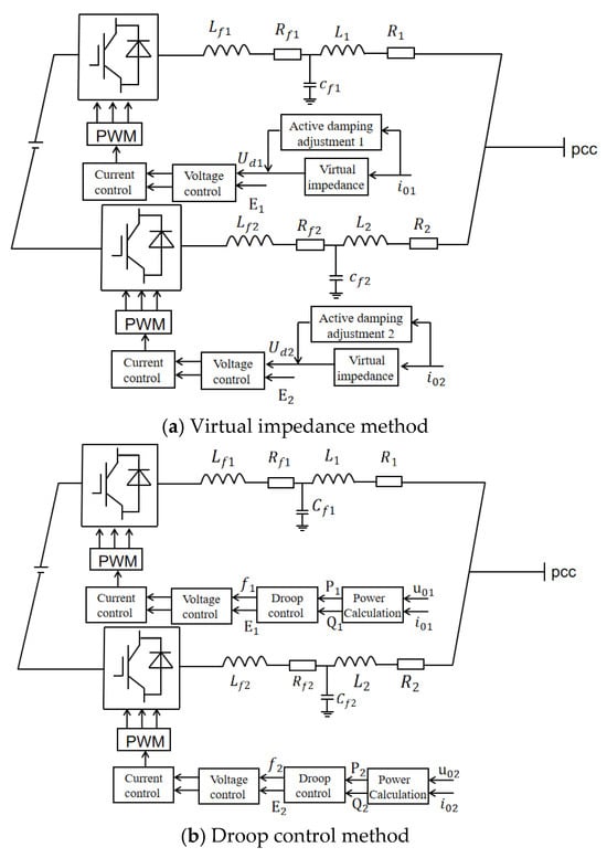
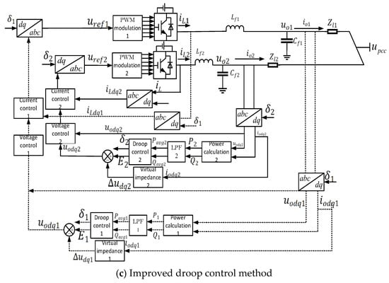
Figure 12.
The system block diagram of the inverter with various control methods.
The system is connected in parallel by two inverters, and the set switching frequency is 10 kHz. and , respectively, represent the proportional gain and integral gain of the voltage outer loop, and they are the core of the PI controller. can respond quickly according to the magnitude of the error, while mainly eliminates the steady-state error of the system. The parameters in Figure 12 are shown in Table 2 and Table 3 below, and Table 2 and Table 3 also list and in the three switch states.
Table 2.
Simulation parameters at a switching frequency of 10 kHz.
Table 3.
Simulation parameters at a switching frequency of 100 kHz.
3. Analysis of Control Effect Comparison
To validate the effectiveness of the proposed power-sharing and circulating current suppression methods, comprehensive simulations are conducted on the paralleled three-phase converter system. The simulation parameters are summarized in Table 4. The paralleled converters are configured with distinct line impedances to emulate near-end and far-end operating conditions. Transmission lines have parasitic parameters such as parasitic resistance. By connecting resistors of different resistance values in series on the line, that is, setting the impedance value of the remote line to six times that of the near line, the working conditions of the near and remote lines can be simulated. Converter 1 (distal position) is characterized by R1 = 0.642 Ω and L1 = 0.246 mH, while Converter 2 (proximal position) implements reduced impedance parameters scaled by a factor of 0.6 (R2 = 0.3852 Ω; L2 = 0.1476 mH).
Table 4.
Simulation parameters.
Figure 13 illustrates the three-phase output voltage/current waveforms and corresponding total harmonic distortion (THD) analyses of parallel-connected inverters under two control methods. As shown in Figure 13a, the virtual impedance method achieves stable three-phase output voltage waveforms with a steady-state amplitude of approximately 380 V. Both inverters maintain balanced voltage sharing during steady-state operation. The output voltages exhibit negligible oscillations or distortions during load transitions, and the current has been maintained at around 6 A all the time. THD analyses reveal voltage and current distortions of 0.61%/0.62% and 0.08%, respectively, confirming the virtual impedance method’s capability to dynamically equalize system impedance imbalances, thereby ensuring superior voltage/current sharing. Figure 13b presents an improved droop control implementation, in which the trigger pulse of the second inverter is intentionally delayed to simulate asynchronous operation. The improved control method can achieve a steady-state voltage amplitude of 380 V, and the voltage sharing among inverters is balanced. The current amplitude is also maintained at around 6 A. The THD measurement shows that the voltage distortion of a single inverter is 2.41% and 2.33% respectively, and the current THD value is 1.89%. Although slightly higher than the virtual impedance method, these improvements were achieved without the communication link between inverters, thereby verifying the cost effectiveness and technical feasibility of the enhanced method.
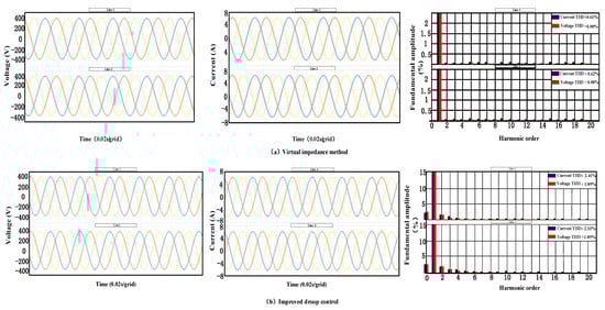
Figure 13.
Output voltage wave, output current wave, and THD of output voltage and current at a switching frequency of 10 kHz. Red, blue and yellow respectively represent the three-phase voltages or three-phase currents of inverters A, B and C. (a) Virtual impedance method. (b) Improved droop control method.
Compared with the voltage and current in Figure 13a, the voltage and current wave at 100 kHz is shown in Figure 14a. It can be seen that the voltage sharing between inverters is balanced. However, it is obvious that the current undergoes distortion to varying degrees, and THD also increases significantly. The THD of voltage and current was 0.11%/0.12% and 0.55%/0.77%, respectively. Figure 14b shows that the switching frequency can also achieve a steady-state voltage amplitude of 380 V, and the voltage sharing between inverters is balanced. Although the current distortion occurs at the 100 kHz switching frequency, the voltage-current THD can rapidly decrease to 2.96%/2.92% and 1.88%, respectively. It demonstrates the obvious advantages of improving the droop control method.
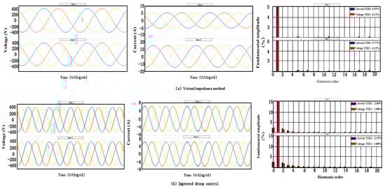
Figure 14.
Output voltage wave, output current wave, and THD of output voltage and current at a switching frequency of 100 kHz. Red, blue and yellow respectively represent the three-phase voltages or three-phase currents of inverters A, B and C. (a) Virtual impedance method. (b) Improved droop control method.
Figure 15 illustrates active power sharing, reactive power sharing, and circulating currents of parallel-connected inverters under control methods. Figure 15a shows the power-sharing performance and cyclic current waveform under the droop control method, and in the droop control, a switch conversion function has been added. However, at the very beginning, there was a slight overcharge phenomenon, and there was a difference in the power distribution of reactive power. Inverter 1 output 19 kW, while inverter 2 output 18 kW. In contrast, Figure 15b presents an improved droop control implementation, achieving synchronous power sharing with a steady-state error of less than 2%. The comparative analysis shows that compared with the traditional droop control, the active power-sharing error of this method is reduced by 4%, and the reactive power balance accuracy is improved by 15.4%. The cyclic current was still limited to ±0.4 A (average) and 0.7 A (peak), and the RMS value is approximately 0.5, representing an 85% suppression compared with the baseline descent method. It is worth noting that this improved method solves the active power-sharing defect observed in the virtual impedance method while eliminating the communication dependence.
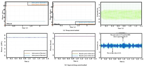
Figure 15.
Active power sharing, reactive power sharing, and circulating currents with two control methods at 10 kHz. (a) Droop control method. (b) Improved droop control method.
Figure 16 explains the power distribution and circulating current phenomenon under different switching frequencies. As shown in Figure 16a, when comparing the switching frequency of 100 kHz with that of Figure 14, which is 10 kHz, the output of inverter 1 is 15 kW, and the output of inverter 2 is 4 kW. As the switching frequency increases, the performance of both active power and reactive power becomes worse. The output of inverter 1 is 3 kVar. Inverter 2 outputs 4.5 kVar. Meanwhile, the average circulating current is around ±9 A, the peak reaches 12 A, and the RMS value is approximately 8.5. In contrast, Figure 16b presents the improved droop control implementation. It can be clearly observed that the switching frequency increases, the average division of reactive power deteriorates, the power remains stable at 0.4 s, inverter 1 has an output of 4.9 kVar, and inverter 2 outputs 5.8 kVar. The load remains constant. When the switching frequency is increased to 100 kHz, the active and reactive waveforms under the new method are as follows:
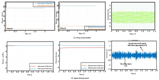
Figure 16.
The active power sharing, reactive power sharing, and circulating currents with two control methods at 100 kHz. (a) Droop control method. (b) Improved droop control method.
This section will compare the virtual impedance and the improved droop method voltage–current THD under different switching frequencies, as well as the power and circulating current of the droop control method and the improved droop method. In terms of power and circulating current, the control effect of the improved droop method is better than that of the droop control method, and at the same time, the control effect of the improved droop method can also achieve the control effect of the virtual impedance control.
4. Experimental Setup and Power Balancing Measurement
In order to measure the current balancing in the motor to evaluate the impact of high switching frequency on power balancing, an experiment setup has been built as shown in Figure 17. This setup is composed of two three-phase, two-level SiC inverters as an experimental set. A 60 V DC power supply is used for the DC input power. We verify the effectiveness of the improved method through low-power experiments. The two-level SiC inverter is controlled by a control board based on a TI TMS320F280049 DSP.
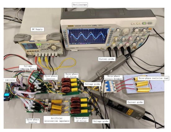
Figure 17.
Experimental setup: SiC inverter and measurement points.
The model of the silicon carbide MOSFET is CI30N65SM. With a high withstand voltage of 650 V, it is suitable for various high-voltage applications, far exceeding ordinary silicon-based MOSFETs. It has a continuous current capacity of 30 A and a typical RDS(on) of 70 mΩ, which is at a relatively good level among 650 V-class SiC MOSFETs. The low on-resistance directly reduces conduction losses and improves system efficiency. The total gate charge of 65 nC and low output capacitance enable fast switching speed, making it suitable for high-frequency applications and significantly reducing switching losses. The manufacturer of the driver chip is Texas Instruments. The gate driver chip uses UCC21520, a dual-channel, high-speed gate driver with isolation function, designed to drive power MOSFETs, IGBTs, and SiC MOSFETs up to 5 MHz, featuring excellent propagation delay and pulse width distortion. Electrical isolation of up to 5 kVrms is achieved between the primary side and the secondary side through a silicon dioxide capacitor. The rated power of the three-phase load is 150 W. It is connected in a star configuration with three 10-ohm 100 W resistors. The voltages of phases A, B, and C are a group of sine waves with an angle difference of 120° between each other.
In this paper, the current and power balancing in the SiC inverter system are evaluated experimentally under various switching frequencies. Although the focus is on the impact of the high switching speed and high switching frequency of SiC converters, other factors are also evaluated to reflect the relative importance between various factors.
Figure 18 presents the output voltage, output current, and corresponding total harmonic distortion (THD) measurements obtained from the hardware system under improved droop control with a switching frequency of 10 kHz. As shown in Figure 18a, the output voltages of inverters 1 and 2 exhibit closely aligned phases and amplitudes, both maintaining approximately 50 V. Similarly, Figure 18b indicates that the output currents of both inverters are nearly identical in phase and magnitude, around 1.8 A. The close matching of both voltage and current waveforms suggests effective mitigation of current-sharing inaccuracies and circulating current in the parallel inverter system. THD analysis reveals that the output voltage THD is 0.21% for inverter 1 and 0.22% for inverter 2, while the output current THD values are 0.29% and 0.23%, respectively. These results indicate that the improved droop control method achieves balanced voltage and current distribution, thereby reducing current imbalance and circulating current effects.
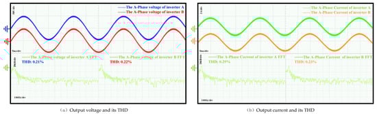
Figure 18.
Experimental results of the equal distribution of output voltage, output current, and THD between two inverters using the improved droop control method at 10 kHz. (a) Output voltage and its THD. (b) Output current and its THD.
Figure 19 presents the output voltage, output current, and corresponding total harmonic distortion (THD) of the system under the improved droop control method at a switching frequency of 100 kHz. As shown in Figure 19a, the output voltages of inverters A and B exhibit closely matched phases and amplitudes, both maintaining approximately 50 V. Similarly, Figure 19b indicates that the output currents of the two inverters are also nearly identical in phase and magnitude, around 1.8 A. The consistency in both voltage and current waveforms demonstrates effective mitigation of current-sharing error and circulating current in the parallel inverter system. THD measurements show that the output voltage THD for both inverters is 0.36%, while the output current THD values are 0.76% for inverter 1 and 0.58% for inverter 2. Compared with the results in Figure 17, the output voltages, output currents, and THD values remain similar across different switching frequencies. This indicates that the improved droop control method maintains consistent performance in voltage and current balancing under high-switching-frequency conditions, effectively suppressing current imbalance and circulating current.
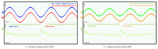
Figure 19.
Experimental results on the equal distribution of output voltage, output current, and THD between two inverters using the improved droop control method at 100 kHz. (a) Output voltage and its THD. (b) Output current and its THD.
As observed in Figure 20, the circulating current is effectively regulated within 0.4 A. A comparison of the active power outputs of the two inverters shows that both units reach their target power levels within a short duration and maintain steady operation within 2 s. During this period, the active power of inverter 1 exceeds that of inverter 2 by approximately 16 W. After adopting the improved droop control method (2 s), the active power of inverter 1 experiences a step decreases of about 9 W, while that of inverter 2 increases abruptly by 12 W, followed by an immediate reduction of approximately 4 W. Thereafter, the active power outputs of both inverters stabilize, with inverter 1 maintaining only about 0.5 W higher than inverter 2, indicating nearly equal power sharing. A similar trend is observed in the reactive power performance. Both inverters achieve their respective reactive power setpoints quickly and remain stable within 2.3 s, during which inverter 1’s reactive power exceeds that of inverter 2 by about 21 Var. After adopting the improved droop control method, the reactive power of inverter 1 drops by 11 Var, while that of inverter 2 rises by 14 Var and then promptly decreases by about 3 Var. Subsequently, the reactive power outputs stabilize, with the difference between the two inverters reduced to approximately 0.5 Var, demonstrating effectively balanced reactive power sharing. These hardware-based verification results align with and further validate the Simulink simulations discussed earlier, confirming that the improved droop control strategy can achieve accurate active and reactive power sharing while effectively suppressing the circulating current.
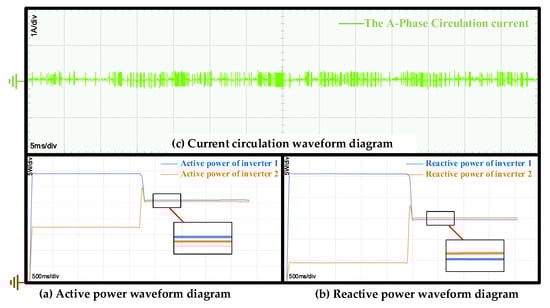
Figure 20.
Experimental results of the equal distribution of active power, reactive power, and circulating current between two inverters using the improved droop control method at 10 kHz. (a) Active power. (b) Reactive power. (c) Circulating current.
Figure 21 presents the circulating current, active power, and reactive power of the two inverters under a switching frequency of 100 kHz. The circulating current is effectively limited within 0.6 A. Analysis of the active power indicates that both inverters reach their target power rapidly and maintain stable operation within 2.2 s. During this period, the active power of inverter 1 is about 15 W higher than that of inverter 2. After adopting the improved droop control method, the active power of inverter 1 decreases abruptly by 8 W, while that of inverter 2 increases by 9 W and then immediately drops by approximately 2 W. Subsequently, the active power outputs stabilize with nearly identical magnitudes. A similar trend is observed in the reactive power response. Both inverters attain steady reactive power within a short time and remain stable for the first 2.3 s, with inverter 1 exhibiting roughly 15 Var higher reactive power than inverter 2. After adopting the improved droop control method, the reactive power of inverter 1 suddenly decreases by 9 Var, while that of inverter 2 rises by 12.5 Var and then promptly declines by about 5 Var. Following this transition, the reactive power stabilizes, with inverter 1 maintaining approximately 2 Var higher than inverter 2. The results demonstrate that even at elevated switching frequencies, the improved droop method achieves effective active and reactive power sharing and maintains strong suppression of the circulating current. A comparison of the results in Figure 19 and Figure 20 reveals that under the improved droop control strategy, high switching frequency has negligible impact on both power equalization and circulating current suppression.
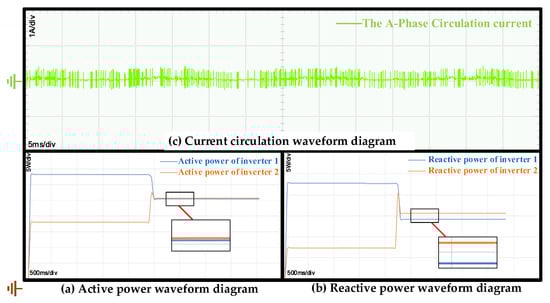
Figure 21.
Experimental results of the equal distribution of active power, reactive power, and circulating current between two inverters using the improved droop control method at 100 kHz. (a) Active power. (b) Reactive power. (c) Circulating current.
5. Conclusions
This paper proposes an improved sag control method, which combines the sag control method with virtual impedance. Firstly, an improved sag control method is established for analysis. Then, a simulation is conducted, comparing and analyzing the waveforms of voltage, current, THD, power, and circulating current obtained under different switching frequencies with the single sag control method. It is concluded that the improved method has a greater advantage in the distribution of reactive power and can better suppress the circulating current. At the same time, the improved method is experimentally verified on this basis, further demonstrating its advantages in power distribution and circulating current suppression.
At the baseline, the voltage THD is around 3%, and the current THD is around 1%. The switching frequency is 10 kHz. The virtual impedance voltage THD is 0.08%, the current THD does not exceed 0.62%, and the RMS value is 0.141. At a switching frequency of 100 kHz, the droop control voltage THD is 0.11%/0.12%, and the current THD does not exceed 0.77%. With the improved droop control, at different switching frequencies, the voltage THDs are all within 2%, the current THD is within 3%, and the RMS values are 0.5 and 1.06, respectively. Experimental validation under hardware conditions further confirms the effectiveness of the proposed method. The results indicate that the circulating current is effectively suppressed within 0.4 A at 10 kHz and 0.6 A at 100 kHz switching frequencies. Both active and reactive power outputs converge rapidly and stabilize with high precision, achieving nearly equal power sharing between the two inverters after transient adjustments. Moreover, output voltage and current waveforms remain well synchronized in both phase and amplitude under different switching conditions, with output voltage THD maintained below 0.36% and current THD below 0.76%.
Author Contributions
Methodology, Z.D.; Software, C.Z.; Validation, Y.S. and F.Y.; Formal analysis, Y.X.; Writing—review and editing, Y.X.; Project administration, C.Z.; Funding acquisition, Z.D. All authors have read and agreed to the published version of the manuscript.
Funding
This work was supported by the Sailing Program of Yibin University under project 2023QH24. This work was supported by the Sichuan Science and Technology Program under project 2024ZYD0267. This work was supported by the Science and Technology Program of Yibin University under project 2020PY08.
Data Availability Statement
The original contributions presented in this study are included in the article. Further inquiries can be directed to the corresponding author.
Conflicts of Interest
The authors declare no conflicts of interest.
References
- Lv, Z.W. Loss Analysis and Efficiency Comparison of Full-Bridge Inverter Based on Si MOSFET and SiC MOSFET. Master’s Thesis, Anhui University of Technology, Ma’anshan, China, 2020. [Google Scholar] [CrossRef]
- Xu, S.; Xu, J. Parallel Control Strategy of Single-Phase Inverter Based on Virtual Impedance. In Proceedings of the 2010 International Conference on Communications, Circuits and Systems (ICCCAS), Chengdu, China, 28–30 July 2010. [Google Scholar]
- Liu, H.Y.; Gao, J.; Wang, M.R.; Hu, T.L.; Xiong, X.F. Based on Current Controlled Voltage Source Parallel Three-Phase Inverter Circulation Control Method. J. Mod. Electr. Power 2016, 1, 27–33. [Google Scholar]
- Liu, K.; Cao, W.; Zhao, J. Dual-Loop-Based Harmonic Current Control Strategy and Admittance Modeling for a Multi-Modular Parallel Saps System. IEEE Trans. Ind. Electron. 2020, 67, 5456–5466. [Google Scholar] [CrossRef]
- Huang, P.; Liu, P.; Xiao, W.; Moursi, M.S. A Novel Droop-Based Average Voltage Sharing Control Strategy for DC Microgrids. IEEE Trans. Smart Grid 2015, 6, 1096–1106. [Google Scholar] [CrossRef]
- Pan, J.; Chen, F.J.; Zhang, Q.; Liu, S.L. Improved Adaptive Droop Control Strategy Based on Inhibition of Circulation. J. Power 2023, 21, 101–109. [Google Scholar]
- Guo, G.; Shi, B. Design of Multiphase DC-DC Main Board Power Controller. Chin. J. Semicond. 2004, 12, 1701–1705. [Google Scholar]
- Roslan, M.A.; Ahmad, M.S.; Isa, M. Circulating Current in Parallel Connected Inverter System. In Proceedings of the 2016 IEEE International Conference on Power and Energy, Melaka, Malaysia, 28–29 November 2016. [Google Scholar]
- Wei, B.; Guerrero, J.M.; Vásquez, J.C.; Guo, X. A Circulating-Current Suppression Method for Parallel-Connected Voltage-Source Inverters with Common DC And AC Buses. IEEE Trans. Ind. Appl. 2017, 53, 3758–3769. [Google Scholar] [CrossRef]
- Li, Z.; Nie, Z.; Ai, S. Nonlinear Modeling and Improved Suppression of Zero-Sequence Circulating Current for Parallel Three-Level Inverters. IEEE J. Emerg. Sel. Top. Power Electron. 2023, 12, 1254–1266. [Google Scholar] [CrossRef]
- Peng, Y.; Hang, F. A Novel Lyapunov Function-Based Nonlinear Controller to Suppress Circulating Current of Paralleled Multi Inverters. In Proceedings of the 2017 International Conference on Computer Systems, Pittsburgh, PA, USA, 18–21 April 2017. [Google Scholar]
- Rawal, M.; Singh, S.K.; Rawat, M.S.; Gupta, T.N. Analysis of ANN Based Enhanced Droop Technique for Appropriate Power Sharing of Parallel Connecting Inverters. In Proceedings of the 1st IEEE International Conference on Emerging Trends in Industry 2021, Raigarh, India, 19–21 May 2021. [Google Scholar]
- Zhao, Y.; Zhu, C.; Liu, J. Much Improved Droop Control Strategy of Inverter Parallel Operation. Electr. Technol. 2022, 15, 26–30. [Google Scholar]
- Zheng, F.; Zhang, H.; Liu, B.; Liang, N.; Wang, W. Research on Cyclic Current Suppression Method for Multi-Inverter Parallel System Based on Adaptive Virtual Complex Impedance. Power Grid Technol. 2025, 49, 1972–1982. [Google Scholar]
- Wei, C.W.; Gong, C.W.; Duan, Y.L.; Zheng, L.Q. Research on Power Allocation Strategy of Microgrid Based on Virtual Impedance. Power Capacit. React. Power Compens. 2020, 41, 169–174. [Google Scholar]
- Wu, Z.; Luo, Y. Research on Parallel Control Strategy of Inverter Based on Virtual Impedance. Power Capacit. React. Power Compens. 2021, 42, 166–172. [Google Scholar]
- Zhang, J.H.; Zhao, R.; Liu, Y.F.; Yang, P.H.; Wu, Z.K.; Zhang, X. Control Strategy for Parallel Operation of Low-Voltage Microgrid Resistive Inverters. High Volt. Technol. 2022, 48, 136–146. [Google Scholar]
- Wang, E.; Wang, S. Droop Control Strategy for Low-Voltage Microgrid Based on Adaptive Virtual Resistor. Power Syst. Prot. Control 2020, 48, 144–149. [Google Scholar]
- Wei, Y.; Xu, D.; Zhou, C. Current Sharing Control of Parallel UPS Systems. Proc. CSEE 2008, 28, 63–67. [Google Scholar]
- Shi, M.; Zheng, X.; Fei, J.; Xie, W.; Yu, J. A Microgrid Stability Improvement Method by Applying Virtual Adaptive Resistor Paralleling with a Grid-Connected Inverter. Energies 2024, 17, 5550. [Google Scholar] [CrossRef]
- Kenta, K.I.; Liu, K.; Zhi, K.; Zanma, T. Current Analysis of Grid-Connected Inverter with VSG Controller Under Voltage Dip and Recovery. Trans. Electr. Electron. Eng. 2020, 15, 1699–1701. [Google Scholar]
- Vikash, G.; Ghosh, A.; Panda, A.K. Parallel Inverter Control Using Different Conventional Control Methods and an Improved Virtual Oscillator Control Method in a Standalone Microgrid. Prot. Control Mod. Power Syst. 2022, 7, 393–405. [Google Scholar]
- Umarov, S.; Sapaev, K. Mathematical Model of a Valve Converter Based on a Parallel Current Inverter with an Adjustable Output Voltage of an Improved Form. In Proceedings of the 4th International Conference on Applied Physics, Information Technologies and Engineering 2022, Bukhara, Uzbekistan, 6–9 October 2022. [Google Scholar]
- Li, M.; Wu, D.; Wang, Z. Research on Reactive Power droop control in Microgrid. Explos.-Proof Electr. Mach. 2025, 60, 5–9. [Google Scholar]
- Zhang, Q.; Peng, C.; Chen, Y.; Jin, G.; Luo, A. A Control Strategy for Parallel Operation of Multiple Inverters in Microgrid. Proc. CSEE 2012, 32, 126–132. [Google Scholar]
- Yao, W.; Chen, M.; Chen, J.J.; Zhu, P.; Qian, Z. A Multi-loop Control Method for Parallel connection of Inverters without Interconnects. J. Electr. Eng. Technol. 2008, 1, 84–89. [Google Scholar]
- Guo, Q.; Lin, L.; Wu, H.; Zhu, P.J.; Qian, Z.M. An Improved droop Control Strategy for Precise Reactive Power Allocation of Distributed Power Sources. Power Syst. Autom. 2015, 39, 30–34. [Google Scholar]
- Ma, J.J. Research on Key Technologies for Parallel Operation of Inverter Systems. Ph.D. Thesis, Harbin University of Technology, Harbin, China, 2022. [Google Scholar]
- Hou, L.Y. Research on Parallel Power Distribution Strategy of Three-Phase Inverters. Ph.D. Thesis, Harbin Institute of Technology, Harbin, China, 2023. [Google Scholar]
- Di Piazza, M.C.; Vitale, G. Circulation Current Suppression in Parallel-Connected PV Inverters Based on a Centralized Control Strategy. IEEE Trans. Ind. Electron. 2017, 64, 5766–5776. [Google Scholar] [CrossRef]
- Li, Y.W.; Kao, C.N. An Accurate Power Control Strategy for Power-Electronics-Interfaced Distributed Generation Units Operating in a Low-Voltage Multibus Microgrid. IEEE Trans. Power Electron. 2009, 24, 2977–2988. [Google Scholar] [CrossRef]
- Wu, L.G.; Ruan, X.B.; Lin, Z.H.; Zhang, H. Circulating Current Analysis of Paralleled Grid-connected Inverters Based on the Multi-frequency Model. In Proceedings of the 2021 IEEE Energy Conversion Congress and Exposition (ECCE), Vancouver, BC, Canada, 10–14 October 2021. [Google Scholar] [CrossRef]
- Zhang, M.; Huang, L.; Yao, W.; Lu, Z. Circulating Harmonic Current Elimination of a CPS-PWM-Based Modular Multilevel Converter with a Plug-In Repetitive Controller. IEEE Trans. Power Electron. 2013, 29, 2083–2097. [Google Scholar] [CrossRef]
- Yao, W.; Chen, M.; Matas, J.; Guerrero, J.M.; Qian, Z.-M. Design and Analysis of the Droop Control Method for Parallel Inverters Considering the Impact of the Complex Impedance on the Power Sharing. IEEE Trans. Ind. Electron. 2011, 58, 576–588. [Google Scholar] [CrossRef]
- Fan, C.H.; Qin, X.H.; Qi, L.; Ding, B.D.; Liu, H.Z.; Meng, Z.J. Analysis of the Role, Improvement and Research Prospect of Virtual Impedance in Grid-type Droop Control. Power Grid Technol. 2024, 48, 2237–2250. [Google Scholar]


Disclaimer/Publisher’s Note: The statements, opinions and data contained in all publications are solely those of the individual author(s) and contributor(s) and not of MDPI and/or the editor(s). MDPI and/or the editor(s) disclaim responsibility for any injury to people or property resulting from any ideas, methods, instructions or products referred to in the content. |
© 2025 by the authors. Licensee MDPI, Basel, Switzerland. This article is an open access article distributed under the terms and conditions of the Creative Commons Attribution (CC BY) license (https://creativecommons.org/licenses/by/4.0/).