Abstract
Understanding drop dispersion behavior is significant to the optimization of liquid dispersion devices. In this work, the drop dispersion behavior in the combined trapezoid spray tray was directly observed and analyzed with a high-speed camera. It was found that the fracture of the liquid neck is the main mode for the liquid column to generate drops. The dispersion behavior of the drops was simulated by CFD, and it was found that the liquid neck is caused by the surrounding vortex field and the uneven pressure distribution inside the liquid column. At the same time, the dispersion time of the drops was counted, and it was found that the drop dispersion time ranges from 5 to 60 ms, depending on the drop diameter and the gas kinetic energy factor in plate hole F0.
1. Introduction
Gas–liquid two-phase flows are widely encountered in numerous engineering fields, such as the petroleum industry [1], chemical industry [2], food production [3], environmental protection [4], and so on [5,6]. Generally, the gas is dispersed as bubbles, or the liquid is dispersed as drops in the other fluid to increase the gas–liquid contacting area and, consequently, to enhance fluid mixing. Accordingly, an excellent fluid dispersion device is of great significance for efficient operation of gas–liquid two-phase flows. The column is one of the most adopted pieces of equipment to complete full contact in gas–liquid two-phase flows [7,8]. It is either used as a reactor, such as the bubble column reactor [9,10], or separator, such as the distillation column [11] and the absorption column [12,13]. Depending on the fluid dispersion medium, columns are divided into the packed column and the tray column [14]. Compared with packed columns, tray columns are more widely used, due to their advantages of simple structure, high fluid dispersion efficiency, and suitable for high pressure conditions [15,16].
The tray is the core component of tray columns. Its structure directly determines the dispersion pattern and operation efficiency of gas–liquid flows. Accordingly, there has always been a research emphasis on developing more excellent trays. Different kinds of trays have been manufactured since the 19th century, such as bubble cap tray, sieve tray, floating valve tray, vertical sieve tray, and so on [17,18]. Among these trays, the combined trapezoid spray tray (CTST), developed by the Hebei University of Technology, exhibits remarkable gas–liquid dispersion performance [19]. It is one of the few trays with the gas kinetic energy factor in empty column FT larger than 3.0 kg0.5s−1m−0.5. Consequently, the CTST has been widely used in pharmaceutical, chemical, petroleum, and other fields [20,21].
The geometrical structure of the CTST is illustrated in Figure 1. It mainly consists of three parts: the bottom perforated plate, the middle trapezoidal spraying cap, and the top separating plate. There are rectangular openings in the bottom perforated plate. They provide the rising channels for the gas to enter the spraying cap. Above the opening is the trapezoidal spraying cap. The cap is analogous to a hollow frustum with two (front and back) supporting trapezoidal plates and two side spraying plates. Generally, spraying caps come in pairs. Arrayed pores are punched in the side spraying plates. Meanwhile, there is a bottom gap between the spraying plate and the bottom perforated plate. It allows the liquid to flow into the spraying cap. The upper separating plate caps the paired spraying caps to reduce entrainment. Between the spraying cap and the separating plate, there is a fluid channel for gas–liquid separation.
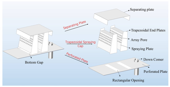
Figure 1.
General structure of the combined trapezoid spray tray (CTST).
The gas–liquid two-phase flow behavior in the CTST is depicted in Figure 2. The gas enters the spray cap through rectangular openings. The liquid accumulated on the bottom plate then enters the spraying cap through the bottom gap, driven by the pressure difference between the two sides of the spraying plate. Accordingly, the liquid spreads out as liquid films along the inner wall of the spraying plates, as lifted by the high-speed gas. As the liquid flows upward, some small drops directly tear off from the liquid film by the gas in the spraying cap.
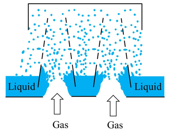
Figure 2.
Gas–liquid flow behavior in the CTST.
Moreover, the majority of the climbing liquid film is ejected through the arrayed pores in the spraying plate and breaks into drops. Part of the liquid film is further carried away by the gas and just collides with the top separating plate. The gas then escapes from between fluid channels, between the top separating plate and the spraying cap, while dispersed drops fall into the liquid layer on the bottom perforated plate. Consequently, the gas and the drops are mixed in the whole three-dimensional space of the CTST [22].
From the above illustration, it is noted that the excellent drop dispersion performance of gas–liquid flows in CTSTs attributes to its distinctive spatial structure. It is the liquid being dispersed as drops to mix with the gas in the whole three-dimensional space of the CTST, rather than the gas being dispersed as bubbles that contact with the liquid layer on the bottom perforated plate. Although engineering application has proved its efficient gas–liquid dispersion performance, the design optimization and practical operation of the CTSTs are still highly dependent on engineering experience, and there is no theoretical basis to accurately predict the performance of the CTST column. The fundamental reason is that we know little regarding to the drop dispersion behavior in the CTSTs, not to mention the quantitative drop dispersion frequency. These basic mechanisms are essential for understanding the excellent gas–liquid dispersion efficiency. However, as a kind of spraying tray, drop dispersion modes in CTSTs are very different from that of the traditional tray: The density and the viscosity of the gas phase are small. Accordingly, the gas phase velocity is required to be rather high to lift the liquid and to disperse it into drops through the arrayed pores in the spraying plate. In such a scenario, it is common to see extensive drop deformation and multivariate fragmentation, resulting in complex drop dispersion behavior. Moreover, there is little research on drop dispersion in the continuous gas fluids in chemical processes, and direct experimental data of spraying drop dispersion is still lacking, which hinders the understanding of drop dispersion in spraying trays such as the CTST, and the design optimization of the spraying trays towards high efficiency and energy saving. In previous studies, the computational fluid dynamics (CFD) simulation has become an important method for analyzing the dispersion behavior and mechanism of drops [23]. Therefore, this paper discusses the dispersion mechanism by establishing a CFD model and studying the flow field distribution in CTSTs.
Studies have shown that most researchers have primarily focused on the modeling, simulation, and computational analysis of two-phase flow in CTSTs, successfully obtaining a series of key information, such as liquid film flow characteristics and droplet distribution laws [24]. However, research on the behavior and mechanisms of droplet dispersion remains a gap in the existing literature, which is far from meeting practical industrial demands. The present work aims to investigate how drops are dispersed in spraying trays (CTSTs as a typical example) and to determine its dispersion mechanism. Section 2 describes the experimental apparatus and how to capture the dispersion behavior of drops. Section 3 describes the method of establishing a simulation model. Section 4 analyzes the experimental results through simulation and experimentation. Section 5 provides a brief conclusion.
2. Experiments
A schematic of the experimental setup is illustrated in Figure 3. It consists of three parts: the CTST column, the fluid delivery system, and the high-speed camera.
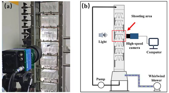
Figure 3.
Experimental setup. (a) Photos of experimental setup; (b) schematic diagram of experimental setup.
The CTST column is approximately one meter long, with seven identical CTSTs evenly arranged along the axial direction. The tray spacing is 100 mm. There are additional fluid distribution plates at both the top and the bottom of the column. The cross-section of the column is 200 mm × 100 mm. The liquid is pumped into the column from the top inlet. It finally accumulates at the bottom settle section, and then discharges through the outlet. The gas is blown into the column from the bottom part, and then leaves at the top outlet of the column. The gas and the liquid are mixed in the CTST. There are two trapezoidal spraying caps in each CTST. The two rectangular apertures at the bottom plate are both 70 mm × 20 mm. The height of the overflow weir at one side of the bottom plate is 10 mm. The bottom gap between the spraying plate and the tray plate is 6 mm. The vertical height of the spraying plate is 70 mm, with an inclination angle of 8 degrees. There are four rows of arrayed pores in each spraying plate. The spacing between adjacent rows is 1 mm. There are nine pores in each row. The diameter of a pore is 5 mm. The top gap between the spraying plate and the separating plate is 20 mm. The geometrical parameters of the CTST are listed in Table 1.

Table 1.
Geometrical parameters of the CTST.
The experiment was carried out at room temperature. First, the air was filtered, and then delivered into the column by the blower, whose maximum flowrate is up to 380 m3/h. The gas flowrate was adjusted by the bypass regulating valve to the desired value. Then, deionized water was pumped into the column via the peristaltic pump. The liquid flowrate was set as 6 L/h. On the one hand, the liquid phase did not flow downward smoothly if the flowrate was small. Moreover, the droplet dispersion events might be insufficient to obtain statistical results. On the other hand, there would be tremendous drops if the liquid flowrate was too large. In such a scenario, the drop dispersion behavior could not be clearly captured. As the liquid flowed downward through the downcomer, it gradually accumulated on the upper surface of the bottom plate of the CTST to form a liquid layer. Meanwhile, it was dispersed as drops via the arranged pores on the spraying plates under the action of the high-speed upwelling gas flow. Next, the liquid continuously flowed downward through the overflow weir to the next tray when the thickness of the liquid layer exceeded the height of the overflow weir. Finally, the liquid accumulated at the bottom settle section and discharged from the column. When the gas–liquid two-phase flow in the column was in steady state, the high-speed camera was started to record the drop behavior.
As previously mentioned, the drop dispersion in the CTST mainly occurs at the arrayed pores in the spraying plates. Accordingly, only drop dispersion via the arrayed pores was recorded and discussed in the present work. Due to the limitation of the column height, the pressure variations in the trays at different heights are relatively small. In the absence of heat or mass transfer, the drop dispersion behavior is the same among the seven CTSTs. In such a scenario, the drop dispersion behavior in the central CTST was captured by the high-speed camera (pco.dimax cs). At the same time, considering the symmetry of CTSTs, the experiment only recorded the dispersion of drops passing through one side of the spraying plate under different conditions. There are 9×4 total rows of jet orifices on the CTST jet plate. The focal length of the high-speed camera is only 18 mm, which is approximately equal to the width of three rows of jet orifices, making it difficult to simultaneously quantify the droplet dispersion phenomenon across the entire jet plate. Therefore, the entire experimental imaging area was divided into three sub-domains. Figure 4 shows the three sub-domains observed in each experiment.
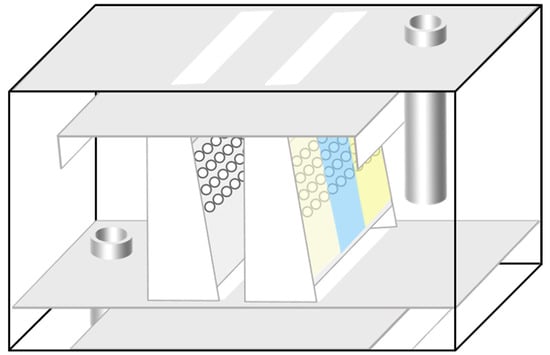
Figure 4.
Experimental shooting area.
After a mass of liquid leaves a pore, on the one hand, it might continuously deform and gradually turn into a drop; on the other hand, the liquid mass also probably eventually breaks into two or more daughter drops. In order to standardize the size of the drops, the diameter of the pore (5 mm) was adopted as the length reference to determine drop diameters. It was determined that the length per pixel is 0.04167 mm. Moreover, the diameter of a drop was measured when it was mostly closed to a sphere (or a circle in a plane) as much as possible. As shown in Figure 5, by measuring the major axis a and the minor axis b of the spherical drop on the plane, in this case, the drop diameter d is approximately equal to [25].
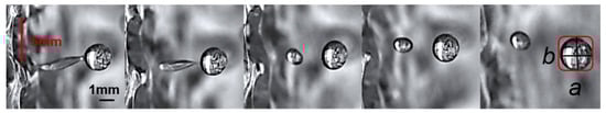
Figure 5.
Statistical method for drop diameter.
The framerate of the high-speed camera was 2000 frames per second. At each sub-domain under every experimental condition, a video lasting for 2 s (4000 frames) was captured and, in total, 15 videos, that is, 60,000 images, were adopted to analyze the drop dispersion behavior. In the present work, experiments were conducted in five different gas flowrate conditions. For consistency, the gas kinetic energy factor in plate hole F0 was used to denote this gas flowrate variable [19], which was calculated by Equation (1), as follows:
where VG is the gas volume flow rate, ρG is the gas density, and AH is the total area of the arrayed pores.
3. Simulation
3.1. Governing Equations
In this study, CFD simulations were performed using the simulation software ANSYS Fluent 2022 R2. The primary focus was on the dynamic behavior of the gas–liquid interface in the CTST, so it was necessary to preserve interface details and surface tension effects. Additionally, both the gas and liquid phases are incompressible fluids. Therefore, a Euler–Euler-based Volume of Fluid (VOF) multiphase flow model was adopted to achieve high-precision analysis of the interphase interface [26,27]. In the VOF model, the continuity equation is shown in Equation (2) [28], as follows:
Only one set of equations is used to describe the flow fields of each fluid in the two-phase flow. The continuity and momentum equations are shown in Equation (3) to Equation (6) [29].
where is the velocity vector of the fluid; μ is the dynamic viscosity of the mixed fluid; and is the surface tension, which is typically calculated using the continuous surface force (CSF) model [30], as follows:
where σ is the surface tension coefficient, and n is the normal vector of the interface.
Considering the complexity of the internal flow field distribution in CTSTs, and the accuracy of the computational results, the RNG k–ε model [31] was selected for simulation calculations. The calculation equations are shown in Equation (9) to Equation (10) [31].
where Gk refers to the turbulent kinetic energy generation term caused by the average velocity gradient.
where Gb refers to the turbulent kinetic energy generated by buoyancy.
where β is the thermal expansion coefficient, and σT is the turbulent Prandtl number.
3.2. Numerical Settings
To reduce the calculation load and focus on the drop dispersion process in the CTST, a reduced domain of the CTST is adopted, as shown in Figure 6a. It keeps the typical spraying structure of the CTST, with four spraying pores in a column. The bottom orifice was set as the gas inlet. A liquid phase inlet was set at the side plane. The top orifice was set as the pressure outlet to the atmosphere. The wall surface was set as a non-slip boundary. The x = 0 plane was set to a symmetrical boundary. Both back and front planes were set as periodic interfaces.
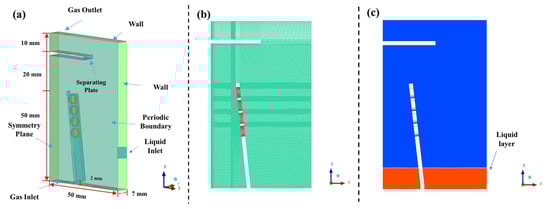
Figure 6.
Diagram of the CTST model. (a) Simulation domain; (b) meshing diagram; and (c) initial gas-liquid phase distribution.
Based on the gas–liquid two-phase flow characteristics and the defined computational domain, the boundary conditions are specified as follows:
- (1)
- Gas Inlet
The gas inlet is defined as a velocity inlet, with the direction perpendicular to the inlet cross-section. The gas inlet velocity is consistent with the superficial gas velocity in experiments.
Inlet velocity:
where V denotes the gas phase flow rate, and D represents the orifice size.
Phase fraction:
The inlet values of k and ε are determined using empirical correlations from the literature [32]. For diffusive flows without vortices at the inlet, the corresponding inlet correlation is expressed as follows:
- (2)
- Liquid Inlet
The liquid inlet is also defined as a velocity inlet, with the direction perpendicular to the inlet cross-section. The liquid inlet velocity was consistent with the liquid inlet velocity in experiments.
Phase fraction:
- (3)
- Boundary Condition for the Outlet
The gas–liquid two-phase outlet is located at the top of the tray, with the direction perpendicular to the gas inlet. The gauge pressure at the outlet was set to 0 Pa.
- (4)
- Boundary Condition for the Wall
In fluid mechanics, the wall boundary condition is used to define the interaction between the fluid and the solid wall. In large-scale fluid dynamics simulations, the wall is typically specified as a no-slip boundary [33], as follows:
In the above equation, i = x, y, z.
- (5)
- Symmetry Boundary Condition
During the physical model construction, the symmetry plane of the model was defined as a symmetry boundary. Consequently, the computational domain exhibits symmetry with respect to the x–z plane. Based on this, for the physical model employed in this study, the symmetry boundary was specified at the center line of the cap cross-section, i.e., at the position where x = 0, as follows:
The computational domain was structured with a hexahedral grid [34,35]. The grids at the orifices and the free gas–liquid interface were refined. The minimum grid size was set at 0.05 mm, and the grids were scaled up by a factor of 1.1 along the vertical direction. The total number of grids was approximately 680,577, as shown in Figure 6b.
The transient governing equations were discretized with the first-order implicit format. The time step was set at 10−5 s. The pressure-implicit splitting operator (PISO) scheme was used for the pressure–velocity coupling. Initially, there was a liquid layer on the bottom plate with a height of 10 mm, as that in experiments, as shown in Figure 6c.
4. Results and Discussion
4.1. Model Verification
The liquid film lifting time, obtained from the simulation calculations, was compared with the experimental results to validate the model. The error results between the two are shown in Figure 7. The time shown in Figure 7 refers to the liquid film lifting time. The liquid film height refers to the height to which the liquid layer on the spraying plate is lifted. As shown in Figure 7, the simulation results are highly consistent with the experimental results, with small errors, indicating that the previously established model can effectively simulate the gas–liquid flow state. More detailed comparisons between simulation and experimental results regarding droplet dispersion behavior are given in Section 4.2 and Section 4.3.
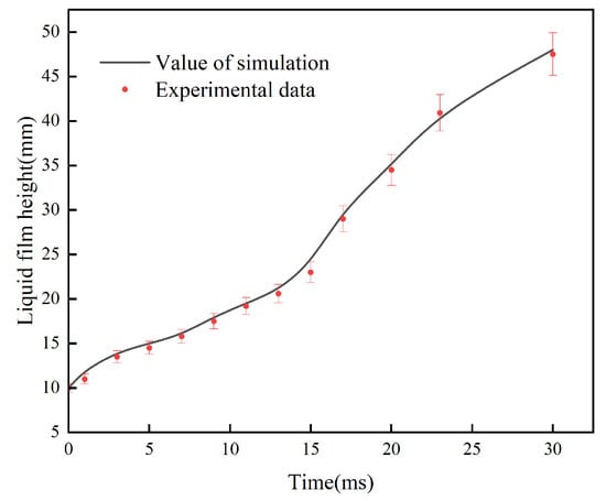
Figure 7.
Comparison of liquid phase height simulation results with experimental results.
4.2. Drop Dispersion
4.2.1. Fracture of Liquid Columns
It is noted that liquid columns are generally formed through arrayed pores at the spraying plates, as shown in Figure 8. In the analysis of liquid column dispersion modes, we introduce the Weber number (We) to describe the ratio of the force exerted on the drop by the external gas flow to the surface tension of the drop itself, which is defined as follows [25]:
where ρ is the density of the liquid, l is the mother drop size, v is the relative velocity of the gas to the drops, and σ is the surface tension. That is, the Weber number (We) is the ratio of the inertial force to the interfacial tension force. This study uses fs to denote the inertial force and fc to denote the cohesive force, which is also the surface tension [36,37].
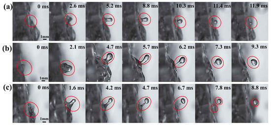
Figure 8.
Liquid column at pores of the spraying plate under the condition of F0 = 18 kg0.5s−1m−0.5. (a) Retraction; (b) drop dispersion of tail fracture, and (c) drop dispersion of head fracture.
Deformation of the liquid column is mainly controlled by the competition of these two forces. The inertial force fs tends to stretch the liquid column and make it thinner. The cohesive force fc attempts to retract the liquid column back into the liquid film. In such a scenario, the liquid column gradually contracts, and no drop is dispersed from the liquid mass if fc dominates, as shown in Figure 8a. However, the liquid column continuously becomes thinner and eventually breaks up to generate a drop if fs is stronger, as shown in Figure 8b,c.
Moreover, it is observed that the thin liquid column might be fractured either from its head or tail to generate a drop. In Figure 8b, the liquid column is not sufficiently elongated when the gas kinetic energy factor in plate hole F0 is small. It retains a bulb-shaped head and connects to the liquid film with a liquid bridge. The thinnest part of the liquid column (that is, the liquid neck) is near the liquid film at the surface of the spraying plate. As the liquid column continuously stretches, the liquid bridge also becomes thinner. Finally, the liquid column is pinched off from its tail. The slender liquid bridge is then absorbed by the bulb-shaped head to form a drop after deformation. In comparison, Figure 8c illustrates that the liquid column is adequately elongated when F0 is large. Accordingly, the liquid neck is near the bulb-shaped head. The liquid column is then pinched off at its head to generate a drop while the thin liquid bridge is absorbed back to the liquid film. Accordingly, the generated drop is smaller than that being pinched off at the tail.
The present study supposes it is the Kelvin–Helmholtz (K-H) instability [38] that leads to the deformation and fracture of liquid columns. K-H instability occurs on the interfaces of two different fluids with a velocity difference. It is well known that velocity differences lead to pressure differences. That is, due to the different velocity distributions inside and outside the CTST cap, K-H instability causes the liquid column to bend the interface, which results in a pressure difference, which is the Laplace pressure at the surface of the liquid column [39,40]. Figure 9 compares two liquid columns in which one liquid neck is near the tail, while the other is near the head.
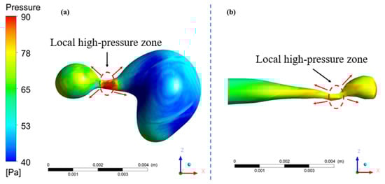
Figure 9.
Schematic diagram of fracture of liquid columns. (a) Tail fracture and (b) head fracture.
At the same time, the magnitude of the Laplace pressure is inversely proportional to the radius of curvature. Accordingly, this pressure difference is largest just at the liquid neck. It tends to push the drop surface around the liquid neck to move towards its center. In such a scenario, the liquid column spontaneously becomes thinner and thinner until being pinched off at the liquid neck, unless external forces, such as the fs, are strong enough to counteract this shearing effect. This explains why liquid necks are always noticed before the fracture of liquid columns.
4.2.2. Tearing of Liquid Films
In CTSTs, some drops are not dispersed through the arrayed pores. On the contrary, they directly tear off from liquid films, as shown in Figure 10. As can be observed from both the experimental images and simulation figures, the liquid film is lifted by the high-speed gas flow and climbs along the inner surface of the spraying plate. Due to the inclined spraying plate, the kinetic energy of the gas flow is partially converted into pressure energy. Consequently, the pressure of the gas flow becomes higher. It is easier to shear off the front of the liquid film to disperse small drops. Some of the drops will merge with the returning liquid striking with the top separating plate, some of the drops will leave with the tray through the fluid channel for gas–liquid separation, and some of the drops will leave through the spraying pores. This drop dispersion mode is only observed under the conditions in which F0 is large. Moreover, the diameter of the dispersed drops is small.
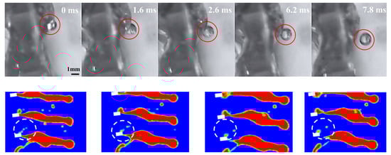
Figure 10.
Schematic diagram of the tearing of liquid film process.
4.2.3. Liquid Film Bag Dispersion
When F0 is large, liquid film breakage occurs in the CTST, as shown in Figure 11. At first, the highest point of the liquid film pressure breaks, triggering a series of liquid film breakages, which ultimately form many small individual daughter drops; this phenomenon is more pronounced in the simulation figures/plots. Some of these daughter drops move with the upward gas flow, some return to the spraying plate, and some of the liquid film that did not form drops also returns to the spraying plate to participate in the next gas–liquid dispersion process.
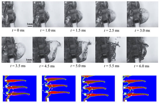
Figure 11.
Liquid film bag crushing phenomenon.
This dispersion phenomenon generally does not form a liquid column. The liquid film dispersed on the spraying plate forms liquid bags through the arrayed pores under the drive of high-speed rising gas. Under the influence of high-speed gas, the pressure on both sides of the liquid film is unbalanced, and the fs inside the liquid film is much larger than the fc. The fc cannot maintain the minimum specific surface area of the liquid bubbles. Under the action of fs, the liquid film eventually breaks into many small drops.
4.3. Formation Mechanism of Liquid Neck
The liquid film forms a liquid column through the spraying pore due to the pressure difference between the inside and outside of the spraying cap. The liquid column forms a liquid neck, due to differences in internal fluid flow, and breaks into drops. Therefore, pressure changes around the liquid column are crucial to the formation of the liquid neck. The simulation results are shown in the Figure 12.
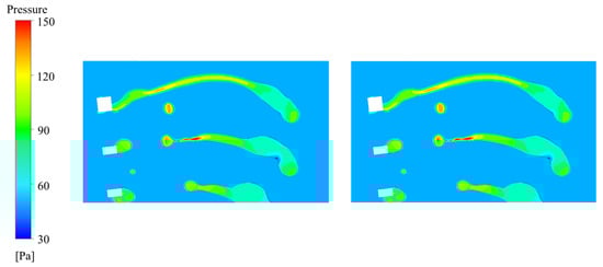
Figure 12.
Drop dispersion diagram.
It is noted that, when the drops dispersed, the spray pores are not completely caped by the liquid film, and the liquid columns mostly form at the edges of the pores. This is related to the uneven pressure at the edges of the pores. Figure 13 shows that the pressure at the top of the pore is significantly higher than that of the surrounding area, and the pressure difference makes it easier for the gas phase to escape from this location, so the probability of a liquid column forming at this location is greater.
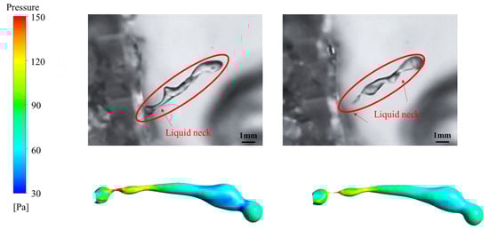
Figure 13.
Changes in the flow field at the neck break of the liquid column.
At the same time, the head of the liquid column is first subjected to Laplace pressure during the conversion of the liquid column into a drop. In other words, whether the liquid film can successfully aggregate to form a complete liquid column depends on the magnitude of the Laplace pressure of the head of the liquid column. Once the Laplace pressure on the head of the liquid column exceeds the critical value, the liquid film will be unable to form a complete liquid column shape, consequently causing the liquid film to retract helplessly into the arrayed pores, which is the experimental phenomenon shown in Figure 8a. Conversely, after the liquid column is successfully formed, due to its own solid obstruction, it will induce one or even multivariate gas field vortices. These vortices attach to the surface of the liquid column, and, considering that the flow of the fluid inside the liquid column is already unbalanced, the superposition of the two ultimately gives rise to the appearance of a liquid neck. In other words, the liquid neck is actually produced by the combination of the vortex of the air field outside the spraying cap and the uneven distribution of fluid pressure inside the liquid column.
4.4. Dispersion Time
In addition to the drop dispersion mode, another important issue regarding drop dispersion is the dispersion time [41]. Solsvik et al. [37] defined the drop dispersion time as the duration from the initial deformation of a spherical drop to the generation of the last daughter drop. This definition is further adopted by Herø et al. [42] and Karimi and Andersson [43]. In this study, since the spacing between the arrayed pores is 1 mm, in order to eliminate the influence of drop dispersion between adjacent rows, the dispersion time is defined as the moment when the drops start to disperse, just as the liquid column emerges from the arrayed pores. The typical dispersion process of the drops passing through the arrayed pores is shown in Figure 14. For the drop dispersion in CTSTs, it ends when the last daughter drop is generated.
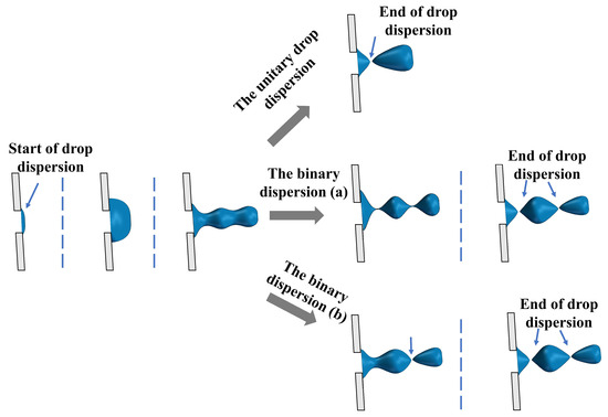
Figure 14.
Schematic of definition of drop dispersion time.
Figure 15 shows the drop dispersion time [44] with different diameters under various gas kinetic energy factors in plate hole F0. If F0 was kept unchanged, the dispersion time of drops with the same diameter is not a constant value, but varies in a certain range. For example, the maximum drop dispersion time is approximately 40 ms, and the minimum is less than 30 ms for 3.25 mm drops when F0 is 10 kg0.5s–1m–0.5. This is because the drop dispersion process is mainly determined by local flow conditions. However, the flow field in the CTST is not uniform. For drops with similar diameters, the dispersion time decreases as F0 increases. For example, the maximum dispersion time decreases from approximately 40 ms to 22 ms, and the minimum dispersion time decreases from approximately 27 ms to 17 ms for 3.25 mm drops when F0 increases from 10 kg0.5s–1m–0.5 to 26 kg0.5s–1m–0.5. This is because, the larger the F0, the more kinetic energy is transferred to the liquid column from the continuous gas phase. Accordingly, the liquid column fractures much easier to generate drops. In addition, the dispersion time becomes longer as the drop diameter increases. For example, the maximum dispersion time increases from approximately 12 ms to 62 ms, and the minimum dispersion time increases from approximately 5 ms to 48 ms when F0 = 10 kg0.5s–1m–0.5 if the drop diameter increases from 0.75 mm to 4.75 mm. More time is required for the liquid column to undergo deformation to generate larger drops.
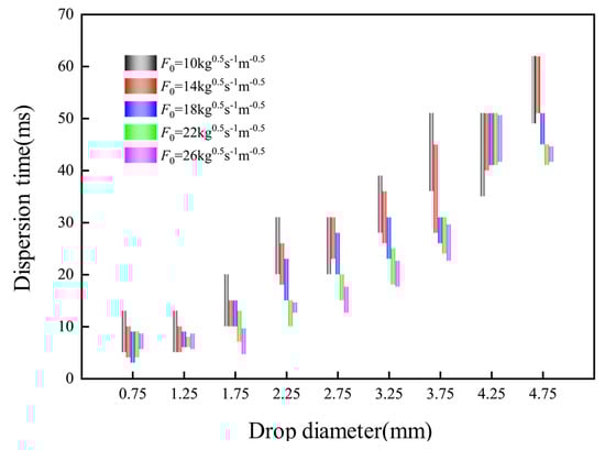
Figure 15.
Influence of drop diameter on dispersion time.
It is noted that, when the drop diameter exceeds about 4.5 mm, there is a slight decrease in the drop dispersion time. This finding is consistent with the results reported in previous studies [44]. The primary reason for this phenomenon is that, when the drop size is small, the main forces determining the drop dispersion are the fs and the fc. However, when the drops produced are too large, on the one hand, the larger drops are subjected to a greater degree of stretching or deformation; on the other hand, the larger the drop size, the more the drop is subjected to the effect of gravity. Both lead to Rayleigh–Taylor (R-T) instability [45], which has an important effect on the drop dispersion behavior, thus shortening the drop dispersion time.
5. Conclusions
In the present work, drop dispersion through arrayed pores in CTSTs is investigated under the different gas kinetic energy factors in plate hole F0. The results show that, when the liquid column is formed in the pore, it may rupture to produce one or more daughter drops. The main modes of drop dispersion are the fracture of the liquid neck, as well as the tearing and breaking of the liquid film. At the same time, the distribution of the flow field inside and outside the spraying cap was studied by simulation, and the formation process of the liquid neck was discussed. The results show that, in CTSTs, the gas field distribution is not uniform, and there are multiple vortices in the whole flow field. At the same time, the pressure increases with the increase in height. Finally, by studying the change in pressure field before and after the fracture of the liquid neck, it was found that the formation of the liquid neck is caused by the eddy current of the gas field and the pressure distribution of the fluid inside the liquid column. Furthermore, the drop dispersion time of drops under differences in F0 was counted. The results showed that the drop dispersion time ranged from 5 to 60 milliseconds. The larger the drop diameter, the longer the dispersion time.
The main innovations of this study are as follows: first, an experimental platform for observing droplet dispersion behavior in CTSTs has been established, and a classification method for droplet dispersion patterns in CTSTs has been determined; second, the dispersion frequencies of different droplet dispersion patterns in the three-dimensional mass transfer tray have been quantitatively analyzed, providing basic data support for the structural optimization and operational control of three-dimensional mass transfer trays; finally, the VOF method has been employed to simulate the droplet dispersion process in CTSTs, revealing the underlying mechanism of droplet dispersion within CTSTs. This study only discusses the influence of gas phase velocity on drop dispersion behavior. The effects of liquid properties, such as surface tension and viscosity, should be further studied to better understand the spray drop dispersion process.
Author Contributions
X.Y.: writing—review and editing; visualization; supervision; and funding acquisition. H.W.: visualization; supervision; and funding acquisition. K.Y.: writing—original draft and writing—review and editing. Q.L.: writing—review and editing. W.S.: visualization; supervision; and funding acquisition. Y.H.: visualization; supervision; and funding acquisition. C.L.: visualization; supervision; and funding acquisition. All authors have read and agreed to the published version of the manuscript.
Funding
We gratefully acknowledge the support of the National Natural Science Foundation of China (22308079, 22378095); the Natural Science Foundation of Hebei Province, China (B2023202025, B2022202008); and the Science and Technology Project of Hebei Education Department, China (BJK2022037).
Data Availability Statement
The original contributions presented in this study are included in the article. Further inquiries can be directed to the corresponding author.
Conflicts of Interest
The authors declare no conflicts of interests.
References
- Tran, B.V.; Nguyen, D.D.; Ngo, S.I.; Lim, Y.I.; Kim, B.; Lee, D.H.; Go, K.S.; Nho, N.S. Hydrodynamics and simulation of air-water homogeneous bubble column under elevated pressure. Aiche J. 2019, 65, e16685. [Google Scholar] [CrossRef]
- Windhab, E.J.; Dressler, M.; Feigl, K.; Fischer, P.; Megias-Alguacil, D. Emulsion processing—From single-drop deformation to design of complex processes and products. Chem. Eng. Sci. 2005, 60, 2101–2113. [Google Scholar] [CrossRef]
- Lee, J.; Yasin, M.; Park, S.; Chang, I.S.; Ha, K.S.; Lee, E.Y.; Lee, J.; Kim, C. Gas-liquid mass transfer coefficient of methane in bubble column reactor. Korean J. Chem. Eng. 2015, 32, 1060–1063. [Google Scholar] [CrossRef]
- Vankova, N.; Tcholakova, S.; Denkov, N.D.; Ivanov, I.B.; Vulchev, V.D.; Danner, T. Emulsification in turbulent flow—1. Mean and maximum drop diameters in inertial and viscous regimes. J. Colloid. Interf. Sci. 2007, 312, 363–380. [Google Scholar] [CrossRef] [PubMed]
- Cao, E.; Radhakrishnan, A.N.P.; bin Hasanudin, R.; Gavriilidis, A. Study of Liquid-Solid Mass Transfer and Hydrodynamics in Micropacked Bed with Gas-Liquid Flow. Ind. Eng. Chem. Res. 2021, 60, 10489–10501. [Google Scholar] [CrossRef] [PubMed]
- Gan, J.; Liu, H.Z.; Chen, J.J.; Li, X.Y.; Li, G.L.; Li, H.; Chen, K.Q. Self-inducing Reactors for Bioengineering. Acs Omega 2023, 8, 48613–48624. [Google Scholar] [CrossRef]
- Olujic, Z.; Jödecke, M.; Shilkin, A.; Schuch, G.; Kaibel, B. Equipment improvement trends in distillation. Chem. Eng. Process. 2009, 48, 1089–1104. [Google Scholar] [CrossRef]
- Li, Q.S.; Li, L.; Zhang, M.X.; Lei, Z.G. Modeling Flow-Guided Sieve Tray Hydraulics Using Computational Fluid Dynamics. Ind. Eng. Chem. Res. 2014, 53, 4480–4488. [Google Scholar] [CrossRef]
- Shu, S.L.; Vidal, D.; Bertrand, F.; Chaouki, J. Multiscale multiphase phenomena in bubble column reactors: A review. Renew. Energ. 2019, 141, 613–631. [Google Scholar] [CrossRef]
- Khan, Z.; Bhusare, V.H.; Joshi, J.B. Comparison of turbulence models for bubble column reactors. Chem. Eng. Sci. 2017, 164, 34–52. [Google Scholar] [CrossRef]
- Fazlollahi, F.; Wankat, P.C. Novel solvent exchange distillation column. Chem. Eng. Sci. 2018, 184, 216–228. [Google Scholar] [CrossRef]
- Yazdipour, F.; Torkmahalleh, M.A.; Kamyabi, M.; Sotudeh-Gharebagh, R. On Solvent Losses in Amine Absorption Columns. Acs Sustain. Chem. Eng. 2022, 10, 11154–11164. [Google Scholar] [CrossRef]
- Majeed, H.; Knuutila, H.K.; Hillestad, M.; Svendsen, H.F. Characterization and modelling of aerosol droplet in absorption columns. Int. J. Greenh. Gas Control 2017, 58, 114–126. [Google Scholar] [CrossRef]
- Roshdi, S.; Kasiri, N.; Hashemabadi, S.H.; Ivakpour, J. Computational fluid dynamics simulation of multiphase flow in packed sieve tray of distillation column. Korean J. Chem. Eng. 2013, 30, 563–573. [Google Scholar] [CrossRef]
- Fang, Q.; Jing, D.; Zhou, H.; Li, S.W. Population balance of droplets in a pulsed disc and doughnut column with wettable internals. Chem. Eng. Sci. 2017, 161, 274–287. [Google Scholar] [CrossRef]
- Wiedemann, P.; Meller, R.; Schubert, M.; Hampel, U. Application of a hybrid multiphase CFD approach to the simulation of gas-liquid flow at a trapezoid fixed valve for distillation trays. Chem. Eng. Res. Des. 2023, 193, 777–786. [Google Scholar] [CrossRef]
- Contreras-Zarazúa, G.; Sánchez-Ramirez, E.; Hernández-Vargas, E.A.; Segovia-Hernández, J.G.; Ramírez, J.J.Q. Process intensification in bio-jet fuel production: Design and control of a catalytic reactive distillation column for oligomerization. Chem. Eng. Process. 2023, 193, 109548. [Google Scholar] [CrossRef]
- Ashtawy, H.M.; Mahapatra, N.R. Molecular Docking for Drug Discovery: Machine-Learning Approaches for Native Pose Prediction of Protein-Ligand Complexes. Lect. N. Bioinformat. 2014, 8452, 15–32. [Google Scholar] [CrossRef]
- Wang, H.; Niu, X.; Li, C.; Li, B.; Yu, W. Combined trapezoid spray tray (CTST)-A novel tray with high separation efficiency and operation flexibility. Chem. Eng. Process. Process Intensif. 2017, 112, 38–46. [Google Scholar] [CrossRef]
- Liang, H.; Chunli, L.; Jidong, L.; Zhenshan, X. Spray Characteristics Study of Combined Trapezoid Spray Tray. China Pet. Process. Petrochem. Technol. 2014, 16, 104–110. [Google Scholar]
- Liu, J.D.; Jiang, K.; Dong, Z.Z.; Xu, J.X. Liquid lifting capability of directed combined trapezoid spray tray. Adv. Mater. Res. 2012, 550–553, 3059–3065. [Google Scholar] [CrossRef]
- Liu, J.; Xie, Z.; He, L.; Liu, Z. Spray characteristics of combined trapezoid spray tray (CTST). J. Chem. Eng. Chin. Univ. 2014, 43, 518–523. [Google Scholar] [CrossRef]
- Mulbah, C.; Kang, C.; Mao, N.; Zhang, W.; Shaikh, A.R.; Teng, S. A review of VOF methods for simulating bubble dynamics. Prog. Nucl. Energ. 2022, 154, 104478. [Google Scholar] [CrossRef]
- Liu, J.; Li, C.; Li, B.; Lv, J. Gas elevating capability of combined trapezoid spray tray. Mod. Chem. Ind. 2002, 22, 104–107. [Google Scholar]
- Misyura, S.Y. Contact angle and droplet evaporation on the smooth and structured wall surface in a wide range of droplet diameters. Appl. Therm. Eng. 2017, 113, 472–480. [Google Scholar] [CrossRef]
- Liu, J.T.; Wang, W.; Chu, N.; Wu, D.Z.; Xu, W.W. Numerical simulations and experimental validation on passive acoustic emissions during bubble formation. Appl. Acoust. 2018, 130, 34–42. [Google Scholar] [CrossRef]
- Albadawi, A.; Donoghue, D.B.; Robinson, A.J.; Murray, D.B.; Delauré, Y.M.C. On the analysis of bubble growth and detachment at low Capillary and Bond numbers using Volume of Fluid and Level Set methods. Chem. Eng. Sci. 2013, 90, 77–91. [Google Scholar] [CrossRef]
- Alitavoli, M.; Khaleghi, E.; Babaei, H.; Mostofi, T.M.; Namazi, N. Modeling and prediction of metallic powder behavior in explosive compaction process by using genetic programming method based on dimensionless numbers. Proc. Inst. Mech. Eng. Part E J. Process. Mech. Eng. 2019, 233, 195–201. [Google Scholar] [CrossRef]
- Eskin, D.; Vikhansky, A.; Mohammadzadeh, O.; Ma, S.M. A model of droplet breakup in a turbulent flow for a high dispersed phase holdup. Chem. Eng. Sci. 2021, 232, 116350. [Google Scholar] [CrossRef]
- Brackbill, J.U.; Kothe, D.B.; Zemach, C. A continuum method for modeling surface tension. J. Comput. Phys. 1992, 100, 335–354. [Google Scholar] [CrossRef]
- Wang, Y.N.; Cao, L.L.; Vanierschot, M.; Cheng, Z.F.; Blanpain, B.; Guo, M.X. Modelling of gas injection into a viscous liquid through a top-submerged lance. Chem. Eng. Sci. 2020, 212, 115359. [Google Scholar] [CrossRef]
- Zarei, A.; Hosseini, S.H.; Rahimi, R. CFD study of weeping rate in the rectangular sieve trays. J. Taiwan Inst. Chem. Eng. 2013, 44, 27–33. [Google Scholar] [CrossRef]
- Parkash, R.; Chauhan, N.; Chauhan, R.P. Application of CFD modeling for indoor radon and thoron dispersion study: A review. J. Environ. Radioact. 2024, 272, 107368. [Google Scholar] [CrossRef]
- Rodriguez Castillo, A.-S.; Biard, P.-F.; Guihéneuf, S.; Paquin, L.; Amrane, A.; Couvert, A. Assessment of VOC absorption in hydrophobic ionic liquids: Measurement of partition and diffusion coefficients and simulation of a packed column. Chem. Eng. J. 2019, 360, 1416–1426. [Google Scholar] [CrossRef]
- Zarei, A.; Hosseini, S.H.; Rahimi, R. CFD and experimental studies of liquid weeping in the circular sieve tray columns. Chem. Eng. Res. Des. 2013, 91, 2333–2345. [Google Scholar] [CrossRef]
- Coulaloglou, C.A.; Tavlarides, L.L. Description of interaction processes in agitated liquid-liquid dispersions. Chem. Eng. Sci. 1977, 32, 1289–1297. [Google Scholar] [CrossRef]
- Solsvik, J.; Tangen, S.; Jakobsen, H.A. On the constitutive equations for fluid particle breakage. Rev. Chem. Eng. 2013, 29, 241–356. [Google Scholar] [CrossRef]
- Dolai, B.; Prajapati, R.P. Kelvin–Helmholtz instability in sheared dusty plasma flows including dust polarization and ion drag forces. Phys. Scr. 2022, 97, 0656037. [Google Scholar] [CrossRef]
- Diemer, R.B.; Olson, J.H. A moment methodology for coagulation and breakage problems: Part 2—Moment models and distribution reconstruction. Chem. Eng. Sci. 2002, 57, 2211–2228. [Google Scholar] [CrossRef]
- Hakansson, A.; Crialesi-Esposito, M.; Nilsson, L.; Brandt, L. A criterion for when an emulsion drop undergoing turbulent deformation has reached a critically deformed state. Colloid. Surface A 2022, 648, 129213. [Google Scholar] [CrossRef]
- Zhou, H.; Yu, X.; Wang, B.; Jing, S.; Lan, W.J.; Li, S.W. Experimental study on drop breakup time and breakup rate with drop swarms in a stirred tank. Aiche J. 2021, 67, e17065. [Google Scholar] [CrossRef]
- Herø, E.H.; La Forgia, N.; Solsvik, J.; Jakobsen, H.A. Single drop breakage in turbulent flow: Statistical data analysis. Chem. Eng. Sci. X 2020, 8, 100082. [Google Scholar] [CrossRef]
- Ashar, M.; Arlov, D.; Carlsson, F.; Innings, F.; Andersson, R. Single droplet breakup in a rotor-stator mixer. Chem. Eng. Sci. 2018, 181, 186–198. [Google Scholar] [CrossRef]
- Zhou, H.; Yu, X.; Wang, B.; Jing, S.; Lan, W.; Li, S. Modeling study on drop breakup time in turbulent dispersions. Chem. Eng. Sci. 2021, 238, 116599. [Google Scholar] [CrossRef]
- Deepak, K.; Ram Prasad, P. Internal waves and Rayleigh–Taylor instability in magnetized compressible strongly coupled dusty plasmas. J. Plasma Phys. 2024, 90, 905900412. [Google Scholar] [CrossRef]


Disclaimer/Publisher’s Note: The statements, opinions and data contained in all publications are solely those of the individual author(s) and contributor(s) and not of MDPI and/or the editor(s). MDPI and/or the editor(s) disclaim responsibility for any injury to people or property resulting from any ideas, methods, instructions or products referred to in the content. |
© 2025 by the authors. Licensee MDPI, Basel, Switzerland. This article is an open access article distributed under the terms and conditions of the Creative Commons Attribution (CC BY) license (https://creativecommons.org/licenses/by/4.0/).