Abstract
Advances in high-performance computing have expanded the use of computational fluid dynamics (CFD) for reacting-flow analysis; however, simulations involving detailed flame kinetics remain computationally intensive for many practical systems. Efficient modeling approaches are therefore essential for predicting flame behavior in swirl-stabilized combustors. This study examines the influence of main-stage swirl intensity on near-lean blow-off characteristics in a multistage swirl combustor using a hybrid RANS–LES framework. The Stress Blended Eddy Simulation (SBES) model, coupled with a Flamelet Generated Manifold (FGM) combustion formulation, is employed to capture key turbulence–chemistry interactions. Results indicate that reducing swirl intensity suppresses the formation of a swirl-stabilized flame, while excessive swirl negatively affects emission performance. For the baseline (S2) and high-swirl (S3) configurations, flame lift-off height increases by 21.0% and 11.96%, respectively, for every 0.1 reduction in equivalence ratio. The S3 case also demonstrates reduced combustion efficiency, with CO emissions rising by 156.4% relative to S2. Local flame extinction is observed in regions of strong droplet–flame interaction, highlighting enhanced quenching susceptibility under near-blow-off conditions. The present study investigates the flame dynamics in a multi-stage swirl combustor using high-fidelity CFD simulations. This study has yet to be validated through experimental analysis and the results presented in this work are entirely computational. Further experimental validation is necessary to verify the results.
1. Introduction
Combustion has played a vital role in human technological development, and modern systems such as internal combustion engines and gas turbines remain indispensable in many sectors. Increasing concerns over greenhouse gas (GHG) emissions and the finite nature of fossil fuel resources, however, have accelerated the transition toward low-carbon propulsion technologies. In 2021, the transportation sector accounted for 29% of total GHG emissions in the United States [1], contributing to a rapid shift toward electrification in road vehicles. Aviation, by contrast, continues to depend on gas turbine engines because alternative propulsion technologies capable of meeting long-range and high-power requirements remain in early development stages. As a result, further improvements in gas turbine efficiency and emissions performance are essential for meeting environmental goals established by organizations such as the Committee on Aviation Environmental Protection (CAEP).
Significant advancements in modern gas turbine design have led to substantial reductions in fuel burn and GHG emissions compared to earlier generations of engines. State-of-the-art combustor technologies, including Lean Direct Injection (LDI), Rich-Burn/Quick-Quench/Lean-Burn (RQL), and Twin Annular Premixed Systems (TAPSs), seek to mitigate harmful emission such as NOx by reducing peak flame temperature through lean, non-stoichiometric operation [2,3,4,5]. While effective, lean combustion inherently increases susceptibility to thermoacoustic instabilities and flame blowout, particularly at low power, low equivalence ratio condition. The equivalence ratio is defined as
where and represent the mass flow rate of fuel and air respectively, and the subscript “st” denotes the stoichiometric condition. A stoichiometric mixture ϕ = 1 represents the ideal balance between fuel and oxidizer, producing the highest flame temperature. As the ϕ deviates from 1, the flame temperature is lowered. Excess reduction in flame temperature can also lead to increased emissions such as CO through incomplete combustion.
While various parameters of single-swirl combustors such as swirl intensity, flow rates, equivalence ratio and their influence on combustion performance are well documented, the understanding of a multi-swirl combustor lags given the increased complexity and variables that are not present in a single-swirler configuration such as co-rotating and counter-rotating swirlers.
This study investigates the influence of main-stage swirl intensity on global flame stability, structure, and emissions in a multi-swirl combustor operating near lean blow-off using a hybrid RANS-LES approach.
Regarding pilot-stage interactions, it should be noted that the present study focuses exclusively on the effects of the main-stage swirl. The combustor geometry and boundary conditions were not configured to allow independent manipulation of the pilot stage. Consequently, the influence of the pilot stage on flow and combustion behavior falls outside the scope of this work.
The present study aims to capture the dominant instability mechanisms and the qualitative trends in flame response for the studied configuration, rather than to provide a fully resolved, scale-by-scale description of turbulence. The RANS-LES approach was adopted, consistent with common practice in complex reacting-flow configurations where full resolution of all turbulent scales is computationally prohibitive [6,7,8,9,10,11,12,13,14,15,16,17,18,19]. This approach focuses on mechanism-oriented insights that are physically consistent and reproducible, providing guidance for understanding unsteady combustion dynamics without requiring fully resolved turbulent statistics.
2. Literature Review
Lean, swirl-stabilized combustion is widely adopted in modern gas turbine engines to reduce NOx emissions while maintaining flame stability via strong central recirculation zones (CRZs) and shear layers that anchor the flame [13]. Single-stage swirlers have been extensively studied, revealing the roles of CRZs, inner and outer shear layers, and processing vortex cores (PVCs) in flame anchoring, mixing, and thermoacoustic behavior [20,21,22,23,24,25]. Multi-stage swirl combustors, including double or concentric swirlers with co- or counter-rotation, are increasingly used in practical devices to tailor flow fields and improve flame anchoring [26,27,28,29,30,31,32,33,34,35,36]. Experimental and numerical studies have shown that swirl configuration influences recirculation zones, flame structure, and overall stability characteristics in dual-stage systems [20,37,38,39,40,41,42,43,44], but detailed investigations under lean, near-blow-off conditions are limited. Lean blowout (LBO) remains a critical challenge in swirl combustion due to the complex coupling between unsteady turbulence, flame extinction–reignition dynamics, and acoustics [22,24,45,46,47]. High-resolution LES and experimental work have begun to characterize blow-off mechanisms in single-stage swirl flames, demonstrating the transient nature of flame extinction and the need for advanced turbulence–chemistry models [24]. However, few studies address LBO in multi-swirl or staged combustors, and those that do primarily focus on spray dynamics and macroscopic blowout behavior rather than detailed mechanisms of shear-layer interactions or unsteady heat-release phenomena specific to multi-stage swirl interactions [22,44]. The current research identified several Key Knowledge Gaps: (i) limited high-fidelity data on flame stability, extinction–reignition cycles, and unsteady thermoacoustic interactions in multi-stage swirl combustors near LBO [48,49,50,51,52,53,54], (ii) insufficient understanding of interacting shear layers and CRZ dynamics in triple-stage or complex swirl configurations under lean conditions [21,45], (iii) scarcity of validated numerical studies (LES or hybrid RANS–LES) capturing unsteady combustion phenomena in multi-swirl combustors with realistic geometry and operating conditions [24] and (iv) lack of experimental benchmarks for validating advanced combustion models in multi-stage swirl flows approaching blow-off limits [55,56,57,58,59,60,61]. Addressing these gaps is essential for designing low-emission, lean-operating multi-stage swirl combustors with reliable performance and flame stability.
3. Computational Model and Method
3.1. Computational Model
Because this study is entirely numerical, the selected combustor geometry must be compatible with validation against peer-reviewed experimental data. Although numerous publications employ triple-swirler combustor configurations, many lack the detailed geometric specifications required for accurate reproduction in 3D CAD environments. The model used in the present work is based on the configuration reported by Vashahi et al. [22], which was chosen due to its comprehensive geometric description and relatively simple design. The corresponding 3D model was generated in SolidWorks 2023 based on the detailed description in the cited work, and the final geometry is illustrated in Figure 1 and Figure 2. The Planum section of the chamber has an axial length of 60 mm and a radius of 37.5 mm. The square combustion chamber has an axial length of 200 mm and a height of 45 mm for the side walls. The geometric detail of the baseline case swirler is shown in Figure 3.
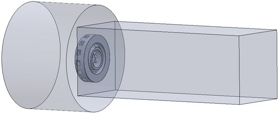
Figure 1.
Swirler computational domain.
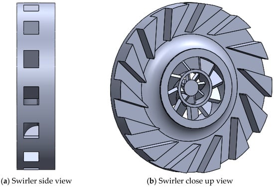
Figure 2.
Swirl design details: (a) Swirler side view, (b) Swirler close up view.
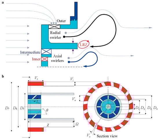
Figure 3.
Schematic of the triple swirler and fluid flow path [22].
The dimensions used in the geometry are shown in Table 1. The main parameter that is being altered in this work is the vane angle of the radial swirler. The vane angle ranges from 20° to 45° and the corresponding swirl number ranges from 0.52 to 1.42. The swirl number is defined as the ratio of the axial flux of angular momentum to the axial flux of axial momentum multiplied by a characteristic radius.

Table 1.
Geometric description of the swirler.
In this work, the swirl number is calculated using a geometry-based Equation (1). In Table 1, S1, S2, and S3 represent the weak, baseline, and strong swirl intensity respectively. The swirl number is given by Equation (2):
The model used in this work has a blockage factor of = 0.35. The CAD models of the three swirlers are presented in Figure 4.
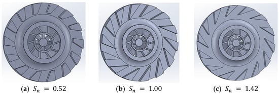
Figure 4.
Swirler design for three swirl numbers: (a) , (b) , (c) .
To adequately capture the flow features in the critical regions, a high-quality mesh was generated using the body-of-influence (BOI) method. The global domain, near-swirler region, and swirler passage were meshed with element sizes of 2 mm, 1 mm, and 0.5 mm, respectively. The finest resolution was applied inside the swirler because the radial momentum induced by the swirler has a direct impact on the downstream flow field and overall solution accuracy. For the volume mesh, polyhedral elements were chosen due to their efficiency in representing complex geometries and their reduced computational cost relative to tetrahedral elements. The final mesh contains approximately 1.9 million elements and is illustrated in Figure 5.
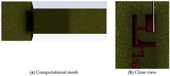
Figure 5.
Swirler mesh: (a) Computational mesh, (b) Close view.
Fully refining the mesh for a wall-resolved LES is computationally prohibitive. Instead, the present study employs the Stress-Blended Eddy Simulation (SBES) model, a hybrid RANS–LES approach that applies RANS near walls and in coarse-grid regions, while utilizing LES in areas capable of resolving the dominant turbulent structures. In the current mesh, the near-swirler region has a cell size of 1 mm, which does not fully resolve the smallest inertial subrange scales. However, SBES models these unresolved scales using RANS, while capturing the largest energy-containing eddies, including shear-layer roll-ups and swirl-induced vortices. This approach provides accurate predictions of the mean flow, and the key turbulence features critical to swirl stabilization and mixing, with smaller-scale fluctuations appropriately modeled. Such behavior is consistent with previous hybrid RANS–LES studies in swirl-stabilized combustors, confirming that the current mesh adequately represents the essential physics of interest [48,49,50,51,62,63,64,65,66].
3.2. Computational Method
The governing equations of fluid dynamics, the Navier–Stokes equations, are derived from the transport equation. These equations are a set of partial differential equations that describe the motion of fluid and consist of (1): conservation of mass and (2) conservation of momentum. The continuity equation, derived from the principle of mass conservation, is given as:
The stress tensor is defined as:
The filtered Navier–Stokes equation, applied in LES, is given as:
As this work utilizes the partially premixed combustion model, the total enthalpy form of the energy equation is applied as detailed in Equation (8)
In this work, the Stress Blended Eddy Simulation (SBES), which is built upon the Shielded Detached Eddy Simulation (SDES), is used. Further details on the SBES model are discussed in a later section. The RANS-LES hybrid turbulence model is a combination of LES and RANS simulation where it utilizes the accuracy of LES outside of the boundary layer while modeling the boundary layer using RANS simulation to avoid the prohibitive boundary layer meshing requirements encountered with traditional LES. The two-equation Shear Stress Transport (SST) model, developed by Menter [24], has been selected for the RANS turbulence model.
Combustion modeling is implemented in this work to simulate the chemical reaction between the fuel and the oxidizer. The model chosen for this study is the Flamelet Generated Manifold (FGM) model. In order to use the flamelet model, the flamelet library along with the Probability Density Function (PDF) table must be generated. In this work, the reduced HyChem A2 mechanism with 44 species and 202 reactions, developed by [44], has been selected to model the reaction of kerosene-based Jet-A fuel. Non-adiabatic energy treatment was selected during flamelet generation to account for heat transfer between the droplets and the gas phase. The enthalpy loss within the non-adiabatic energy treatment is described as follows:
Additionally, diffusion flamelet type was chosen, as the flow is predominantly non-premixed. For the stream boundary condition, 300 K and 400 K have been selected for fuel and oxidizer respectively. The following equations for species mass fraction (Equation (12)) and temperature (Equation (13)) are solved to generate the flamelet over a range of scalar dissipation . In this work, flamelets are generated for scalar dissipation rates ranging from up to , at which point the flame is extinguished. The flamelet generation parameters are summarized in Table 2.
Table 2.
FGM table parameters.
3.3. Time Step Characterization
Each case has been simulated for a physical flow time of 0.1 s with a time-step size of and an inner iteration of 30. The flow time has been selected based on a previous study where the blowoff transient ranged between 10 ms and 30 ms [53]. Each case was run for 0.5 s of physical flow time before collecting the unsteady statistics for 0.1 s. The unsteady statistics have been collected every 5 timestep for a total of 1000 sample points. Based on the inlet velocity, the resulting CFL number for this work is presented in Equation (14). The selected discretization schemes are shown in Table 3.
Table 3.
Discretization scheme.
3.4. Boundary Conditions
The three boundary conditions for this study are the mass-flow inlet, pressure-outlet, and the walls, as shown in Table 4. The fuel spray injection is modeled using the Discrete Phase Model (DPM). For the baseline case, the inlet mass flow rate and the outlet pressure are adopted from previous studies conducted by [47] to serve as a reference. For the air inlet, the mass fraction of is set to 0.21, and the mass fraction of is set to 0.79, as the sum of all species must equal 1. The fuel flow is specified as pure jet-A fuel, POSF10325, with an average formula of and a model formula of . The pressure-swirl atomizer model (utilizing the Linearized Instability Sheet Atomization (LISA) model) was selected as for the spray injection modeling. Details of the numerical schemes are presented in Table 5.
Table 4.
Boundary conditions details.
Table 5.
Details of numerical scheme.
3.5. Numerical Model Data Validation
An experimental reacting flow study has yet to be carried out using the multi-stage swirler model by Vashahi et al. (2019) [22]; thus, the numerical model must first be validated through replicating a known experimental study. In this work the validation is made against a study conducted using the Cambridge Swirl Burner (CSB). If the combustion model can accurately replicate the combustion phenomena of the CSB, it can be considered satisfactory for the current problem.
The three-dimensional geometry of the Cambridge Swirl Burner (CSB) was generated in SolidWorks 2023 based on the dimensions provided in Figure 6. The burner consists of a single axial swirler and a bluff body. The swirler contains six vanes set at a 60° angle, corresponding to a swirl number of [61]. The bluff-body diameter is = 25 mm, and the experimental combustion chamber length is L = 150 mm. For the present simulations, the chamber length was extended to 340 mm to mitigate potential outlet-induced recirculation effects.
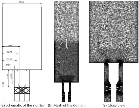
Figure 6.
Swirler schematic and mesh details: (a) Schematic of the swirler, (b) Mesh of the domain, (c) Close view.
Mesh generation was performed in ANSYS 2024 using polyhedral cells to accommodate the geometric complexity near the swirler. A global maximum cell size of 4 mm was applied throughout the domain. Finer mesh spacing was introduced near the swirler and swirler exit to resolve the swirling flow. To manage computational cost, the extended downstream region beyond the experimental 150 mm chamber height retained the coarse 4 mm cell limit, whereas the annular tube and the first 150 mm of the combustor were refined to 2.5 mm. Two bodies of influence were employed: one around the swirler with a target mesh size of 1 mm, and one surrounding the bluff body and nearby combustor region with a target size of 2 mm. The final mesh shown in Figure 6a,b contains approximately 2 × 10⁶ polyhedral elements. The numerical setup is consistent with that used in the primary study. A uniform inlet velocity of 10.73 m/s was specified at the inlet boundary. The discrete phase fuel mass-flow rate ranged from 0.27 g/s to 0.154 g/s, depending on the validation condition. The simulated operating cases used for validation are listed in Table 6.
Table 6.
Details of the case studies.
Uncertainty analysis was performed based on the axial velocity using computational and experimental data, at the locations shown in Figure 7. The data validation is presented in Figure 8 and Figure 9.
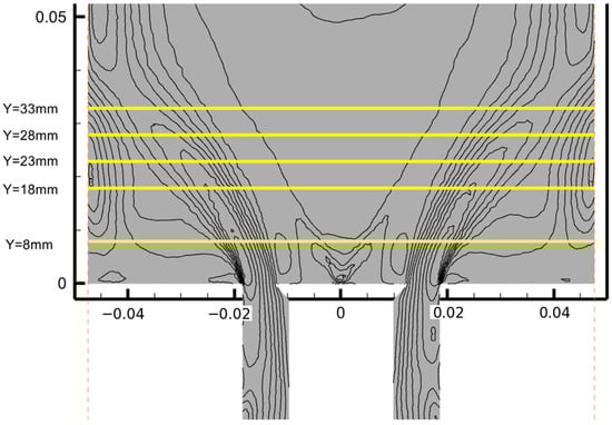
Figure 7.
Flow field interrogation regions.
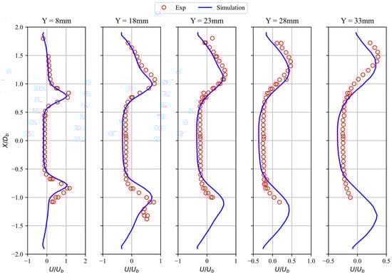
Figure 8.
Validation of computational data.
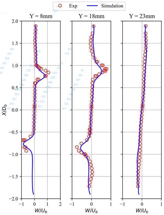
Figure 9.
Validation of computational data.
The quantitative uncertainty analysis is presented in Table 7. We note that multi-stage swirlers involve complex interactions between concentric shear layers, absent in the CSB, so validation against CSB data does not fully capture all features of the triple-stage geometry. The CSB-based validation ensures that the numerical framework, including turbulence modeling and combustion treatment, accurately repro-duces essential swirl-stabilized flame physics, such as flame anchoring and mean flow characteristics, common to both single- and multi-stage swirlers. While the CSB provides a reliable benchmark for validating the numerical framework, it lacks the concentric, inter-acting shear layers characteristic of multi-stage swirlers. As a result, phenomena that arise from inter-stage interactions, such as modulation of recirculation zones, altered vortex breakdown locations, and combined swirl-induced mixing effects, are not captured in this validation. We highlight that, although the framework reliably reproduces fundamental flame anchoring and mean flow features, the specific multi-stage flow dynamics require cautious interpretation, and exact quantitative predictions of inter-stage effects remain a subject for future experimental or high-fidelity validation. This approach maintains transparency while demonstrating that the framework reliably captures the primary flow and flame features relevant to the triple-stage configuration.
Table 7.
Uncertainty analysis.
4. Data Validation
Multi-Stage Burner
A mesh-independence study was conducted to determine the adequacy of the computational grid. Normalized axial velocity profiles at y/D = 0.26, shown in Figure 10, were compared with the experimental measurements reported in [22].
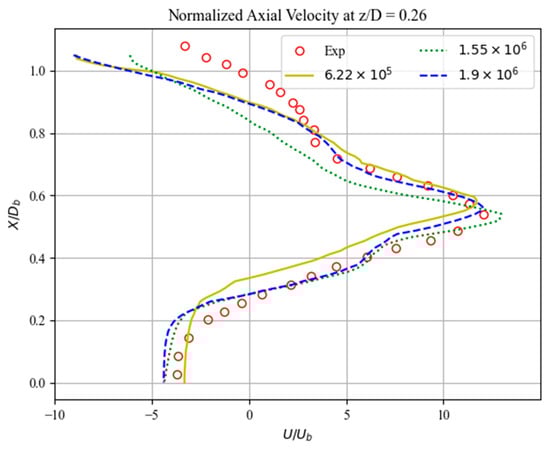
Figure 10.
Grid-independence analysis.
Three polyhedral mesh densities, 6.22 × 10⁵, 1.55 × 10⁶, and 1.9 × 10⁶ cells, were evaluated, as summarized in Table 8. Because the reference experiments provide data over only half of the tangential domain due to axial symmetry, the numerical comparison was restricted to the same region. The assessment focused on the peak normalized axial velocity and its axial location. All meshes yielded similar trends, with errors remaining below 10%. The finest mesh, composed of 1.9 × 10⁶ cells, produced the lowest overall error, with deviations of 0.28% in peak magnitude and 4.15% in peak location. Therefore, the 1.9 × 10⁶-cell mesh was selected for use in the present study.
Table 8.
Uncertainty analysis.
It should be noted that the mesh sensitivity analysis presented in this study was limited to non-reacting flow conditions. Formal grid convergence for key reacting-flow quantities, including mean temperature, species mass fractions, and extinction/reignition dynamics, has not been demonstrated. While the adopted mesh resolution is consistent with common practice in LES studies of similar combustor configurations, the quantitative accuracy of flame-related predictions may be influenced by grid resolution. Accordingly, absolute values should be interpreted with caution, and the results are primarily intended to provide qualitative insight into dominant mechanisms and trend-based flame behavior rather than high-precision quantitative prediction.
For hybrid RANS–LES approaches, a classical grid convergence study is generally not meaningful because the turbulence closure depends explicitly on the local grid spacing. Mesh refinement changes the RANS–LES blending and shifts the modeled–resolved interface, so different grids do not represent the same effective governing model. As a result, mesh differences reflect both modeling and resolution effects rather than purely numerical discretization error [51,52,53]. This grid dependence has been widely discussed in the LES and hybrid RANS–LES literature [52,55,56,57]. For reacting flows, the requirement to simultaneously resolve thin reaction zones, strong density gradients, and turbulence–chemistry interaction scales would imply near-DNS resolution, which is computationally prohibitive for practical configurations [58]. Accordingly, consistent with common practice, the present work uses a grid sensitivity and resolution-quality assessment based on key statistical quantities and accepted RANS-LES resolution indicators instead of a formal asymptotic grid convergence study [58,59,60,61].
While a formal mesh refinement study was not conducted as part of the present work, the simulations were carried out using a mesh resolution that has been commonly employed in comparable reacting flow and swirl-stabilized combustor studies reported in the literature. Previous investigations have shown that this mesh can capture the primary flow features and overall combustion characteristics, including recirculation zones and global temperature and species trends [37]. Although local quantities may exhibit some sensitivity to grid resolution, the chosen mesh is considered adequate for the qualitative and comparative analyses presented in this study, and the main conclusions are not expected to be significantly affected.
While a full mesh refinement study was not conducted for the reacting cases, the mesh resolution was selected based on established practices in the reacting flow CFD literature, which demonstrate that adequately refined meshes can capture key mean combustion features with limited sensitivity to further refinement [37,38]. Previous studies have shown that, for LES of reacting flows in complex combustors, quantities such as mean temperature, reaction rates, and velocity fields are relatively insensitive to grid size [37,38]. Furthermore, the mesh employed in the present simulations has been widely used in similar reacting flow studies and has been shown to accurately reproduce main flow and combustion characteristics [37,38]. We acknowledge this limitation and therefore focus our analysis on trends and comparative behavior, which are less dependent on absolute mesh refinement.
The numerical methodology used in this study, including the hybrid RANS–LES framework, turbulence closure, combustion modeling, and numerical discretization, has been extensively validated in the literature for both single- and multi-swirler swirl-stabilized combustors under comparable operating conditions [37,38]. The present simulations capture key flow features such as the formation of the central recirculation zone, vortex breakdown location, swirl-induced shear layers, and flame anchoring behavior, all of which align well with results reported in high-fidelity experimental and LES studies of multi-stage swirl injectors [37,38]. Specifically, the predicted central recirculation zone exhibits a size and location consistent with experimental observations, indicating accurate representation of the global flow stabilization mechanism. The vortex breakdown location and the development of swirl-induced shear layers match trends reported in LES studies, demonstrating that the hybrid RANS–LES approach can reliably capture unsteady flow structures relevant to flame anchoring. Furthermore, the simulated flame attachment points correspond closely with experimental flame stabilization data, supporting the validity of the combustion modeling approach in multi-stage swirl configurations. These comparisons collectively confirm that the present results are not only qualitatively consistent but also quantitatively supported by existing high-fidelity studies of similar configurations.
We acknowledge that, in a strict LES context, the current 1.9 M cell mesh does not constitute a fully converged fine mesh, and a more refined grid (~4 M cells or higher) would be required to rigorously demonstrate full LES grid independence. However, the present study employs the Stress-Blended Eddy Simulation (SBES) hybrid RANS–LES approach, which blends RANS in regions where the mesh cannot resolve the smallest turbulent scales with LES in regions capable of capturing the large, energy-containing eddies. In this framework, the dominant flow structures governing flame lift-off, swirl stabilization, and large-scale mixing are well resolved on the 1.9 M cell mesh, while smaller-scale turbulence is modeled via RANS. This behavior has been widely documented in hybrid RANS–LES studies [23,24,25,26].
Grid sensitivity trends observed across 0.62 M, 1.55 M, and 1.9 M meshes show that mean flow quantities vary with refinement; the 1.9 M cell mesh provides a practical compromise that adequately resolves the essential large-scale structures relevant to the physical phenomena of interest. While a fully converged LES would require substantially more cells, the current results are consistent with prior SBES studies of swirl-stabilized combustors and are sufficient to capture the key physics of flame lift-off and emissions [37,38]. This limitation has been clarified in Section 3.1, highlighting both the hybrid nature of SBES and the adequacy of the current mesh for the study objectives.
Large-eddy simulation (LES) is inherently a statistical approach in which the governing equations are spatially filtered, and the effects of unresolved motions are represented through subgrid-scale (SGS) modeling [24,25]. Unlike Reynolds-averaged Navier–Stokes (RANS) simulations, which solve directly for ensemble-averaged quantities, LES resolves the large, energy-containing turbulent motions while modeling the statistical influence of the smaller, unresolved scales [26]. Because the filter width is implicitly linked to the grid resolution, mesh refinement in LES modifies the effective filtering operation and therefore changes the governing equations themselves, rather than merely reducing numerical discretization error [23,25]. Accordingly, LES is not expected to exhibit classical pointwise grid independence. Instead, simulation quality is commonly assessed using resolution criteria and statistical measures that quantify the relative contribution of resolved and modeled turbulence.
For reacting flows, the application of classical grid-convergence studies is further complicated by the fact that grid refinement simultaneously alters the resolved turbulence spectrum and the modeled turbulence–chemistry interaction, effectively modifying the combined physical–numerical model rather than isolating discretization error [27,28,29,30]. As a result, grid refinement in reacting LES does not constitute a purely asymptotic convergence process in the traditional sense.
In the present study, a single, carefully designed LES grid was therefore employed, and solution quality was evaluated using established LES resolution indicators, consistent with prior LES studies of reacting flows [6,7,8,9,10,11,12]. The analysis focuses on the convergence of relevant statistical quantities and the consistency of physically meaningful flow trends. Therefore, the results are not intended to demonstrate formal grid independence in the classical sense, but rather to support qualitative physical interpretation within the defined scope of the study.
The absence of direct experimental or high-fidelity DNS/LES validation for the exact multi-swirler geometry considered in this work limits the quantitative reliability of the predicted temperature and velocity fields. Consequently, the results should be interpreted primarily in a qualitative and comparative sense, focusing on flow–flame interaction mechanisms and relative trends rather than absolute values.
While Pope’s criterion provides a useful quantitative metric for assessing LES resolution quality [23,24], it is not universally required for LES-based investigations that primarily target integral flow behavior, dominant unsteady modes, or comparative trends rather than full spectral resolution of turbulence [27,28]. This is particularly true for reacting flows, where grid refinement modifies the resolved turbulence scales and the associated turbulence–chemistry interaction, effectively altering the modeled system rather than yielding a classical grid-converged solution [29,30]. In the present work, the adequacy of the numerical approach is therefore evaluated based on the consistency of global flow features, the robustness of dominant unsteady modes, and the repeatability of observed trends across operating conditions. A comprehensive grid refinement campaign aimed at strictly satisfying Pope’s criterion was considered beyond the scope of this study and is explicitly acknowledged as a limitation of the present analysis.
5. Results
5.1. Cold Flow
5.1.1. Mean Flow Structure
The mean axial velocity contours under cold-flow conditions are shown in Figure 11. For case (a), the swirled jet (SJ) follows a predominantly axial trajectory after exiting the swirler, whereas cases (b) and (c) exhibit a larger deviation angle relative to the flow direction. This behavior is expected, as increasing swirl number enhances the tangential momentum of the SJ relative to its axial component. The influence of swirl intensity is clearly observed in the location of the SJ stagnation point, defined as the point on the wall surface where the axial velocity is zero between the SJ and the corner recirculation zone. As the swirl number increases, this stagnation point shifts upstream. The swirl intensity also affects the size and shape of the Central Recirculation Zone (CRZ), outlined by the black contour, which is characterized by regions of negative axial velocity.
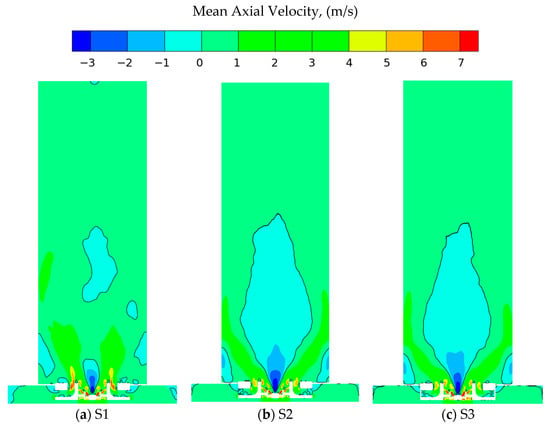
Figure 11.
Swirl number effect on the mean axial velocity, (a) S1, (b) S2, (c) S3.
Figure 12 shows the swirl impact on the axial velocity, at different axial locations inside the swirl combustor. To better characterize the flow field, the axial velocity contours were superimposed with a 2D vector field, as shown in Figure 13. The region of negative axial velocity within the CRZ is clearly visible for cases (b) and (c). In addition to the CRZ, several vortical structures appear within the shear layer separating the CRZ from the swirler jet in these two cases. Although a conventional CRZ does not form in case (a), a region of stagnant flow is observed well above the swirler. The upper boundary of this stagnation zone aligns with the upper edge of the CRZ identified in cases (b) and (c).
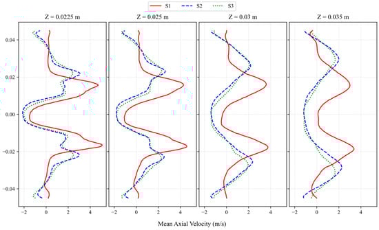
Figure 12.
Swirl number effect on the mean axial velocity.
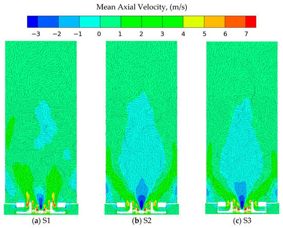
Figure 13.
Swirl number effect on the mean-axial velocity, overlaid with vector field: (a) S1, (b) S2, (c) S3.
The size of the Central Recirculation Zone (CRZ), shown in Figure 14, was determined by extracting the coordinates of the zero–axial velocity line, which defines the CRZ boundary. This representation also highlights the wall-surface stagnation point. For S1, the stagnation point occurs at Z = 7.2 cm, while for S2 and S3 it shifts upstream to Z = 6.6 cm and Z = 5.8 cm, respectively. The CRZ length also correlates with the swirl number, Sn: relative to S1, the CRZ lengths in S2 and S3 are 5.7% and 10.3% shorter. The CRZ width exhibits an interesting trend. The CRZ boundaries for S2 and S3 remain nearly identical until the swirling jet interacts with the wall. At this location, the CRZ corresponding to the highest Sn collapses first due to the onset of vortex breakdown, while those with lower Sn undergo collapse farther downstream. Consequently, an increase in Sn leads to a smaller CRZ, whereas a lower Sn produces a larger one. This relationship has been consistently reported in previous studies for both single-stage and multi-stage swirling flows.
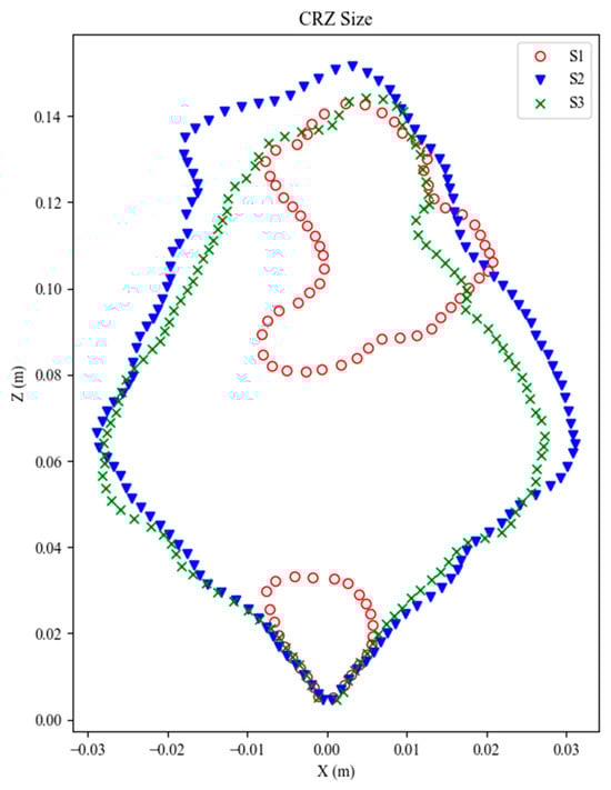
Figure 14.
Swirl number effect on the CRZ.
5.1.2. Turbulence Characteristics
The TKE distribution under cold-flow conditions is shown in Figure 15. All three cases exhibit a similar overall TKE structure, with the highest levels occurring along the shear layer immediately above the injector. As is common in swirling flows, this shear layer experiences elevated turbulence due to the strong velocity gradients present. In this configuration, the effect is further amplified by the spray injection, where high-velocity droplets interact with the surrounding fluid. These large velocity gradients are also evident in Figure 12 and Figure 13. Downstream of the injection region, elevated TKE is observed within the lip recirculation zone, highlighted in Figure 12 and Figure 13, located between the intermediate and main stage swirlers. This region corresponds to the interaction zone of the two counter-rotating swirling jets, where substantial shear further enhances turbulence levels.
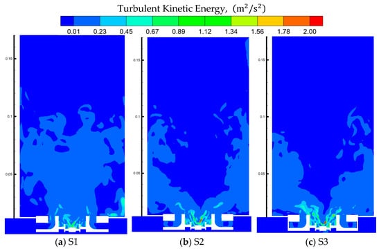
Figure 15.
Swirl number effect on the turbulence kinetic energy: (a) S1, (b) S2, (c) S3.
The TKE contour along the axial plane is shown in Figure 16. For all three cases, the highest turbulence levels occur at Z = 2.25 cm, closest to the swirler where most turbulence is generated. In case (a), the TKE remains concentrated near the centerline with minimal outward spreading. In contrast, cases (b) and (c) exhibit a ring-like TKE distribution with a low-turbulence region at the core. This pattern results from the turbulent swirling jet occupying the outer region, while the central ‘hole’ corresponds to recirculated flow that has already dissipated much of its turbulent energy. As the flow moves downstream, turbulence decays, leading to reduced TKE magnitude and a broader distribution. This effect is evident at Z = 3.5 cm, where the ring structure expands relative to that at Z = 2.25 cm. Overall, cases (b) and (c) exhibit very similar behavior, while case (a) shows distinct differences.
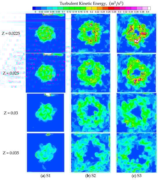
Figure 16.
Axial distribution of turbulence kinetic energy (TKE): (a) S1, (b) S2, (c) S3.
5.1.3. Vortical Structures
The mean Z-vorticity was computed, and the resulting contours across the combustor cross-section are shown in Figure 17a–c. The mean Z-vorticity is evaluated using
where positive values denote counterclockwise rotation and negative values indicate clockwise rotation. Although the geometry contains three swirlers, the vorticity field exhibits a more complex flow structure with more than three distinct rotating features. The three innermost vortical regions correspond to the swirlers themselves. In contrast, the outer finger-like structure is not produced by the swirlers but instead originates from a vortex generated within the main-stage swirler channel. The iso-surface visualization further shows that the rotating flows produced by the different swirlers yield similar vorticity distributions, resulting in a generally homogeneous swirling jet across all three swirler configurations, despite differences in their designs.
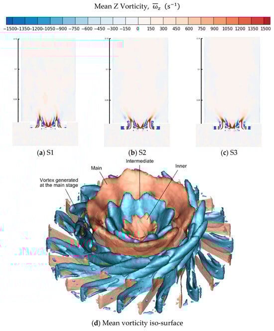
Figure 17.
Swirl number effect on the mean vorticity: (a) S1, (b) S2, (c) S3, (d) mean vorticity iso-surface.
The mean Z-vorticity along the axial plane is presented in Figure 18, illustrating how the vorticity field evolves as the flow moves downstream. For all cases, the highest vorticity occurs near the swirler, where angular momentum is imparted to the incoming flow.
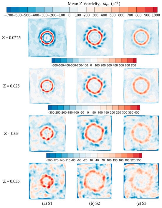
Figure 18.
Swirl number effect on the mean vorticity; axial direction: (a) S1, (b) S2, (c) S3.
At Z = 2.25cm, two dominant vorticity structures are clearly visible: one generated by the main-stage swirler, appearing as a homogeneous counterclockwise (CCW) rotating region, and another finger-like vortex also originating from the main stage. The strength of these homogeneous vortices is nearly twice that of the vortices formed by the intermediate stage swirler. The CCW vorticity consists of multiple small, circularly arranged regions, consistent with the structures observed in Figure 17d. These features are most pronounced near the swirler exit, where the swirling jet has not yet dissipated or fully entrained the surrounding fluid. No distinct vortices are observed from the inner stage swirler, likely due to its comparatively low mass flow rate. By Z = 2.5 cm, the peak mean vorticity decreases substantially, by approximately 40% for V1 and 30% for V2. At this location, compared with Z = 2.25 cm, vortex structures begin to lose coherence as entrainment increases and swirling motion decays. The rotating flow also moves farther from the central axis as a result of centrifugal effects. Further downstream, these trends continue: vortex intensity diminishes, rotational structures disperse into the surrounding fluid, and the swirling region expands outward with increasing axial distance.
Figure 19 presents the mean Z-vorticity fields for the three swirl configurations (S1, S2, and S3). Clear differences in the strength, structure, and distribution of rotational motion emerge as the swirl number increases. For S1, the vorticity field exhibits two well-defined concentric regions of alternating positive and negative vorticity. The vorticity magnitude is highest in this case, indicating strong rotational motion imparted by the swirler. The ring structures are compact and symmetric, reflecting a highly coherent and stable vortex pattern. For S2, the vorticity distribution becomes less uniform. Although the ring of alternating vorticity is still present, it is more distorted, showing lobed or finger-like shapes around the circumference. These distortions suggest increased azimuthal instability and enhanced interaction between the shear layers. The peak vorticity magnitude remains significant but is lower than that of S1, indicating a partial weakening of the rotational core. For S3, the mean vorticity field displays the smoothest and broadest distribution among the three cases. The vorticity ring is noticeably more diffuse, with substantially lower peak values. The flow exhibits fewer small-scale vortical features, which is consistent with the reduced rotational energy at the lowest swirl number. As swirl decreases, the swirling jet becomes less effective at generating strong shear-driven vortices, leading to a weaker and more dispersed vorticity field. Overall, the comparison demonstrates that higher swirl numbers produce stronger, more coherent, and more sharply defined vorticity structures, while lower swirl numbers result in weaker, more diffuse rotational motion. This trend aligns with the expected influence of swirl intensity on vortex generation and stability within swirling combustor flows.
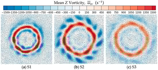
Figure 19.
Swirl number effect on the mean vorticity: (a) S1, (b) S2, (c) S3.
5.2. Reacting Flow
5.2.1. Mean Flow Structure
The mean axial velocity distribution under reacting flow conditions is shown in Figure 20. The flow behavior differs noticeably from that of the cold-flow cases. For S1, only minor changes in the velocity field occur. The characteristic stagnation zone and the CRZ at the swirler exit persist, and despite variations in the equivalence ratio (ϕ), the overall flow structure remains largely unchanged. In contrast, S2 exhibits substantial deviations from its cold-flow behavior. A stable CRZ does not consistently form. At ϕ = 0.5, recirculation is limited primarily to the region influenced by spray injection. At ϕ = 0.4 and ϕ = 0.3, a CRZ is present; however, it appears to split around Z = 5 cm, suggesting potential flow instability. Additionally, the spread angle of the swirling jet (SJ) increases under reacting conditions, resulting in a lower wall stagnation point compared to the cold-flow case. S3 shows trends similar to S2, with noticeable inconsistencies across the three equivalence ratios. At ϕ = 0.5 and ϕ = 0.3, regions of elevated axial velocity appear.
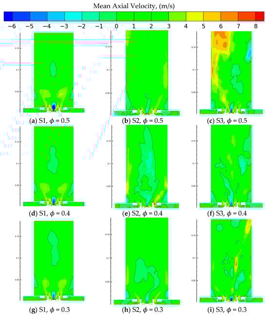
Figure 20.
Swirl number and equivalence ratio effects on the mean axial-velocity: (a) S1, (b) S2, (c) S3, (d) S1, (e) S2, (f) S3, (g) S1, (h) S2, (i) S3.
The velocity spikes were examined through time-step and grid-sensitivity studies. Reducing the time step or refining the mesh slightly attenuates the oscillations without altering overall flow trends, indicating that the spikes are numerical rather than physical. The localized velocity spikes observed very near blow-off exhibit numerical sensitivity and are not used as primary evidence for conclusions on flame stability. Instead, the analysis focuses on time-averaged fields, dominant unsteady modes, and systematic trends approaching blow-off, which remain numerically well behaved and consistent across simulations. Within the context of LES as a statistical approach, these simulations are designed to capture the integral and dominant flow–flame behavior rather than fully resolving all turbulent scales, consistent with the considerations of Pope [24,25]. The presence of localized numerical artifacts delineates the limits of the approach but does not compromise the broader physical interpretation. Thus, the main findings are drawn from regimes where solver behavior is robust.
Such spurious oscillations are well documented in CFD and are commonly associated with discretization errors and nonlinear numerical effects when spatial and temporal resolutions are not fully converged [39,40,41].
The selected grid and time step balance accuracy and numerical stability; independence studies confirm that key mean flow features and integral quantities are insensitive to further refinement, consistent with standard CFD verification practices [39,40,42,43]. Although time-step reduction alone did not fully remove the oscillations, prior studies show that monotonicity-preserving or more dissipative schemes can mitigate such numerical artifacts. Investigation of these approaches is therefore identified as future work.
Figure 21 presents the mean axial velocity profiles at four axial locations (Z = 0.0225 m, 0.025 m, 0.03 m, and 0.035 m) for the three swirl numbers S1, S2, and S3 under reacting conditions at an equivalence ratio of ϕ = 0.5. Across all axial locations, S1 exhibits the highest peak axial velocity near the jet centerline, indicating stronger jet penetration and a more stable core flow. The shape of the S1 profile remains consistent downstream, with only moderate decay in velocity magnitude. For S2, the axial velocity is noticeably lower than S1 and shows greater asymmetry in the outer shear-layer regions. The reduced peak velocity suggests weaker jet momentum and enhanced radial spreading compared to S1. This behavior is consistent with the increased swirl, which redistributes axial momentum outward and promotes stronger mixing. The S3 profiles show the lowest centerline axial velocities among the three cases. The velocity distribution is flatter near the center and more skewed in the outer radial regions, indicating significant radial transport of momentum caused by the highest swirl intensity. The progressive widening of the velocity profile with axial distance reflects enhanced entrainment and rapid decay of jet momentum. Overall, increasing the swirl number reduces the centerline axial velocity and increases radial spreading of the flow. These trends are consistently observed across all axial locations, demonstrating the strong influence of swirl intensity on the reacting flow structure at ϕ = 0.5.
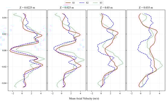
Figure 21.
Swirl number effect on the mean axial-velocity; ϕ = 0.5.
Figure 22 presents the mean axial velocity profiles at ϕ = 0.4 for swirl numbers S1, S2, and S3 at four axial locations (Z = 0.0225 m, 0.025 m, 0.03 m, and 0.035 m). Across all stations, S1 exhibits the highest centerline axial velocity, reflecting a stronger jet-like core relative to the other cases. The S2 case shows a broader velocity distribution with a more gradual radial decay, indicating enhanced radial spreading associated with its higher swirl intensity. In contrast, S3 displays the most attenuated axial velocity, with pronounced velocity deficits near the centerline and increased radial redistribution at all axial positions. As the flow moves downstream, the profiles of S2 and S3 continue to flatten, consistent with increased entrainment and mixing driven by stronger swirling motion. Conversely, S1 retains a relatively distinct central peak throughout the measurement domain. These results highlight the influence of swirl number on flow development under reacting conditions, where higher swirl intensities (S2 and S3) promote greater radial transport and centerline velocity reduction, while lower swirl (S1) maintains a more focused axial stream.
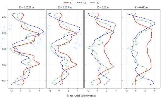
Figure 22.
Swirl number effect on the mean axial velocity; ϕ = 0.4.
Figure 23 presents the mean axial velocity profiles at four axial locations (Z = 0.0225, 0.025, 0.03, and 0.035 m) for swirl numbers S1, S2, and S3 under reacting conditions at an equivalence ratio of 0.3. Across all axial planes, S1 exhibits the most pronounced centerline velocity deficit, consistent with a stronger and more stable central recirculation zone (CRZ). The velocity gradients for S1 remain steep, and the outer shear-layer peaks are more distinguishable relative to the higher-swirl cases. In contrast, S2 demonstrates a more uniform velocity distribution, with reduced centerline reversal and weakened shear-layer peaks, indicating partial breakdown of the CRZ and enhanced radial spreading of the swirling jet. The S3 profiles show even smoother gradients and the smallest magnitude of centerline deficit among the three cases, suggesting that the CRZ is either significantly weakened or intermittently formed at this low equivalence ratio. As the flow progresses downstream from Z = 0.0225 m to Z = 0.035 m, all cases display reduced velocity magnitude due to dissipation; however, the relative differences among swirl numbers persist. Overall, the results show that decreasing the equivalence ratio dampens swirl-induced recirculation, with S1 maintaining the strongest recirculation signature and S3 exhibiting the weakest, reflecting the increased susceptibility of high-swirl flows to instability at lean operating conditions.
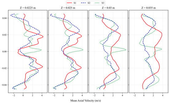
Figure 23.
Swirl number effect on the mean axial velocity; ϕ = 0.3.
5.2.2. Temperature Distributions
The instantaneous temperature field is presented in Figure 24. All flames exhibit a highly wrinkled surface, reflecting strong interactions with the turbulent flow field. Signs of local extinction are also apparent in most cases. The S1 case displays an extended high-temperature region resembling a co-flow jet flame, with pronounced wrinkling in the outer shear layer. This effect is particularly evident at ϕ = 0.5 between Z = 3 cm and Z = 10 cm. Beyond Z = 10 cm, the wrinkling diminishes, and the interface between the hot gas and its surroundings becomes smoother. Additionally, the S1 case shows a low-temperature zone along the central axis from the swirler up to Z = 8 cm, indicating that the flame front remains confined to the outer shear layer without significant mixing with the core flow, a feature characteristic of co-flow jet flames. At Z = 8 cm, however, a high-temperature core emerges for ϕ = 0.5 and ϕ = 0.4. This region of elevated temperature coincides with areas of flow stagnation and recirculation, suggesting that the flame is aerodynamically anchored at this location.
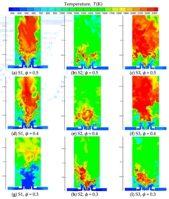
Figure 24.
Swirl number and ϕ effects on instantaneous temperature field: (a) S1, (b) S2, (c) S3, (d) S1, (e) S2, (f) S3, (g) S1, (h) S2, (i) S3.
The mean temperature field, shown in Figure 25 and Figure 26, also indicates a temperature rise in this region. At ϕ = 0.3, a sharp temperature drop is observed, signifying flame blow-off and the cessation of combustion. For case S2, the high-temperature region above 2000 K is highly localized, closely corresponding to the flame front. The absence of elevated temperatures beyond Z = 8 cm suggests that hot gases are being recirculated, a conclusion further supported by the high temperatures observed along the central axis. Although the flame shapes differ among the three ϕ cases, such variability is expected for turbulent flames and is not necessarily a consequence of the equivalence ratio. Notably, fluctuations in flame lift-off height are observed: ϕ = 0.5 and 0.3 exhibit lower lift-off heights, while ϕ = 0.4 shows a higher lift-off. The mean temperature field also demonstrates a decrease in peak temperature with decreasing ϕ. Compared to S1, case S2 exhibits a high-temperature region closer to the swirler, consistent with the SJ profiles in Figure 27. In S1, the SJ extends up to Z = 3.5 cm, whereas in S2 it reaches only Z = 2.2 cm. A comparison between instantaneous and mean results reveals differences in the combustion zone. The instantaneous temperatures approach the adiabatic limit, while mean temperatures in the same region are 300–400 K lower, indicating that the flame does not remain fixed but moves with the flow field, experiencing local extinctions. As the equivalence ratio decreases, local extinction becomes more frequent, creating numerous “holes” in the flame sheet, which in turn reduces the mean temperature in this region.
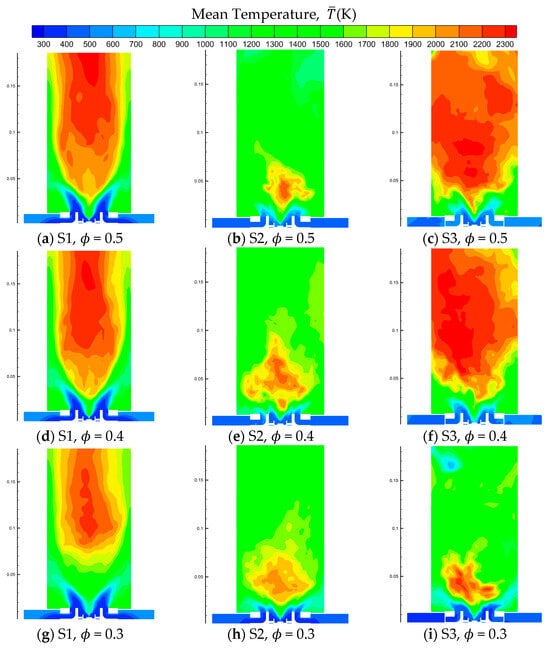
Figure 25.
Swirl number and ϕ effects on mean temperature field: (a) S1, (b) S2, (c) S3, (d) S1, (e) S2, (f) S3, (g) S1, (h) S2, (i) S3.
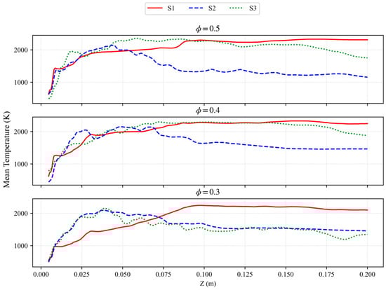
Figure 26.
Equivalence ratio (ϕ) effect on the mean temperature along the axial centerline.
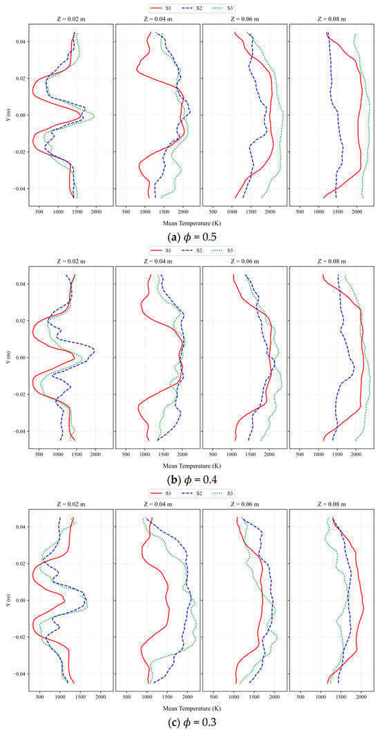
Figure 27.
Swirl number effect on the mean temperature: (a) ϕ = 0.5, (b) ϕ = 0.4, (c) ϕ = 0.3.
Figure 26 presents the mean temperature profiles along the axial centerline for the three swirl configurations (S1, S2, and S3) at equivalence ratios 0.5, 0.4, and 0.3. For all cases, the temperature increases sharply within the first 20–30 mm downstream of the injector, reflecting rapid heat release in the near-field reaction zone. At ϕ = 0.5, S1 and S3 exhibit comparable peak temperatures of approximately 2100–2300 K, whereas S2 reaches a substantially lower maximum of about 1800 K and decays more rapidly beyond 60 mm.
At ϕ = 0.4, the overall trends remain similar, though peak temperatures are slightly reduced. S1 maintains the highest and most spatially uniform temperature distribution, sustaining values above 2000 K over much of the axial length. S3 continues to follow closely, while S2 again exhibits an early reduction in temperature, dropping below 1500 K beyond 70 mm, suggesting partial flame weakening at reduced equivalence ratio. For the leanest condition, ϕ = 0.3, all configurations show further reduction in peak temperatures; however, the relative differences persist. S1 maintains the most robust thermal field, with axial temperatures remaining above 1800 K over a significant portion of the combustor. S3 demonstrates moderate stability, while S2 experiences the strongest degradation, with temperatures gradually declining to nearly 1200 K toward the outlet.
Although S2 exhibits slightly lower peak centerline temperatures than S1 and S3, its moderate swirl enhances mixing uniformity and flame stability, resulting in superior emissions performance, particularly under lean conditions. S2 therefore represents a practical compromise between peak temperature and overall combustion quality. The non-monotonic dependence of temperature on swirl number arises from competing physical mechanisms. While increasing swirl intensifies turbulence and mixing, excessive swirl can induce strong recirculation and vortex breakdown, leading to local flame lift-off or partial extinction and reduced peak temperatures. Swirl also modifies central recirculation zone dynamics, altering residence time and redistributing high-temperature regions both axially and radially. At higher swirl levels, increased shear and strain rates may further suppress local reaction rates, contributing to temperature variations.
The designation of S2 as providing an optimal balance is based on combined emissions and stability considerations. Compared with S1 and S3, S2 achieves more uniform temperature and species distributions, lower CO emissions at lean conditions, stable flame anchoring, and reduced risks of hot spots or flame detachment. Thus, the balance reflects a trade-off between maximizing peak temperature and ensuring stable, uniform, and efficient combustion rather than peak temperature alone.
Figure 27 presents the radial distribution of mean temperature at four axial locations (Z = 0.02 m, 0.04 m, 0.06 m, and 0.08 m) for swirl configurations S1, S2, and S3 under three equivalence ratios. Overall, the temperature field exhibits strong sensitivity to both swirl intensity and mixture strength, with leaner conditions producing lower peak temperatures and more pronounced differences among the swirlers. At ϕ = 0.5, all three swirlers display well-defined high-temperature regions, with peak values generally exceeding 1800–2000 K across the sampled axial planes. S1 consistently produces the highest temperatures, particularly near the centerline where values reach above 2000 K at Z ≥ 0.04 m. These trends indicate that under richer conditions, lack of vortex breakdown in the low-swirl condition (S1), compared to baseline swirl case (S2), yields higher temperature in downstream location while exhibiting reduced temperature homogeneity across the sample plane. High-swirl case (S3) on the other hand exhibits both increased temperature and temperature homogeneity, indicating increased level of mixing and heat release.
At ϕ = 0.4, peak temperatures decrease moderately for all cases, but the structural differences remain similar. S1 maintains the strongest thermal field across all axial locations, sustaining temperatures around 1800–2000 K. S3 displays a comparable distribution at the front of the combustor (Z = 0.02 m), but its temperature dissipates more rapidly, creating a more homogenous distribution downstream.
S2 shows the greatest reduction in flame temperature, with values at Z = 0.06 m and 0.08 m falling to approximately 1200–1500 K. This combined with the peak temperature near 2000 K at Z = 0.02 m suggests that under intermediate equivalence ratio, the reaction zone moves upstream, and the majority of the chemical energy is released at the front of the combustor (Z = 0.02–0.04 m).
Under the leanest condition, ϕ = 0.3, the cooling effect becomes more pronounced. Peak temperatures across all swirlers are significantly lower, with S1 again exhibiting the highest values, reaching approximately 1600–1800 K at mid-length positions. S2 shows moderately lower peaks and a narrower high-temperature core, indicating partial weakening of the reaction zone. S3 experiences the strongest reduction in thermal output, with temperatures at Z ≥ 0.06 m frequently approaching or falling below 1200 K, suggesting substantial flame weakening and possible localized extinction. The diminished temperature gradients and asymmetries observed in the S3 profiles are characteristic of operation near blow-off.
Overall, the results clearly show that at low swirl intensity (S1) the onset of heat release is delayed due to the weakened recirculation, while baseline and high swirl cases (S2 and S3) experienced increased temperature levels at the front of the combustor (Z = 0.02–0.04 m). Subsequently, the reaction zone for low swirl (S1) is extended further downstream, showcasing higher peak temperature compared to baseline and high swirl (S2 and S3) cases.
5.2.3. Flame Topology
The lift-off height, calculated from the OH mass fraction, is presented in Figure 28. The probability distributions for all cases reflect the chaotic nature of turbulent flames, with lift-off heights spanning the full measurement range. The S1 flame exhibits the highest overall lift-off, centered at 17 mm, and displays a relatively uniform distribution around this value. It should be noted that for ϕ = 0.3 in S1, measurements are reported, but these only include data prior to flame extinction, as points beyond the measurement range were excluded. For S2, ϕ = 0.5 shows a pronounced peak at 15 mm. At ϕ = 0.4, the primary peak occurs at 16 mm, but additional peaks are observed at 5 mm and 23 mm, indicating multiple preferred lift-off positions. At ϕ = 0.3, the lift-off height decreases to 11 mm, with no dominant peak, suggesting significant flame oscillations. In all S3 cases, the peak remains at 17 mm; however, as the equivalence ratio decreases, the probability density at 17 mm diminishes while the density of lower lift-off values (1–10 mm) increases, reflecting enhanced flame instability.
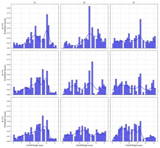
Figure 28.
Impact of equivalence ratio (ϕ) on the flame lift-off height.
The lift-off height based on mean temperature is shown in Figure 29a. Although this approach does not capture the full distribution of fluctuating values, its simplicity and clear representation make it a useful alternative. Most cases, except S3 at ϕ = 0.3, exhibit an increase in lift-off height with decreasing equivalence ratio. The large spike observed in S1 at ϕ = 0.3 likely results from flame extinction and does not indicate a stabilized lift-off height of 40 mm. For S1, the lift-off height increases by 26.9% from ϕ = 0.5 to 0.4. In S2 and S3, each 0.1 reduction in ϕ corresponds to an average lift-off height increase of 21.0% and 11.96%, respectively.
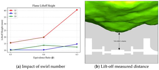
Figure 29.
Impact of equivalence ratio (ϕ) on the flame lift-off height: (a) Impact of swirl number, (b) Lift- off measured distance.
As discussed in previous sections, flame shapes vary with swirl number. While 2D temperature contours reveal the influence of turbulence, they do not capture its full three-dimensional nature. To better illustrate the impact of turbulence on the flame surface, the instantaneous temperature iso-surface is presented in Figure 30.
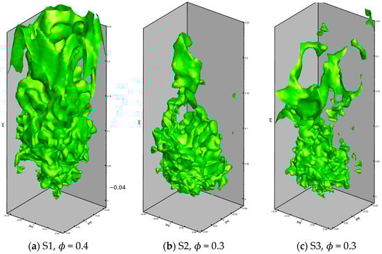
Figure 30.
Swirl number effect on the temperature field; iso-surface (T = 1600 K): (a) S1, ϕ = 0.4, (b) S2, ϕ = 0.3, (c) S3, ϕ = 0.3.
In an LDI combustor, heat loss from evaporating droplets can cause flame quenching and local extinction, as illustrated in Figure 31. Quenching occurs in regions with elevated droplet evaporation, highlighting the significant impact of droplet–flame interactions, particularly at low ϕ. If not mitigated, such local extinctions can propagate and potentially lead to global flame extinction.
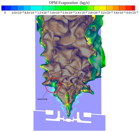
Figure 31.
Quenching and flame extension.
5.2.4. Species and Emissions
Figure 32 shows the effect of swirl number and equivalence ratio on the CO2 mass-fraction field within the combustor. For all swirl numbers, the CO2 concentration increases with ϕ, consistent with higher overall heat release and more complete oxidation at richer conditions. At low ϕ, the flow exhibits extended regions of low CO2 mass fraction near the injector exit, indicating weak reaction intensity and partial flame quenching. As ϕ increases, these low-CO2 zones contract, and the high-CO2 core grows upward along the combustor axis. Changes in swirl intensity further modify the spatial distribution of CO2. At low S, the high-CO2 region remains confined near the central shear layer, with limited lateral spreading. Increasing S strengthens radial transport and enhances mixing, producing a broader CO2 distribution and reducing the axial extent of the high-CO2 core. High-swirl cases exhibit a pronounced recirculation zone that transports combustion products upstream, resulting in elevated CO2 mass fractions near the injector plane and a thicker, more stable flame brush. Overall, the results demonstrate that CO2 formation scales primarily with ϕ, whereas swirl number dictates its spatial redistribution through modifications to mixing and recirculation behavior.
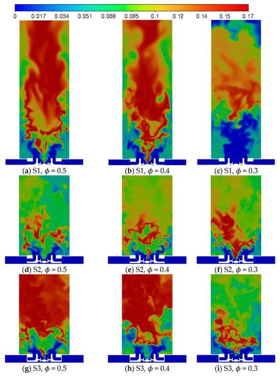
Figure 32.
Swirl number and ϕ impacts on the CO2 mass fraction: (a) S1, (b) S2, (c) S3, (d) S1, (e) S2, (f) S3, (g) S1, (h) S2, (i) S3.
Figure 33 presents the influence of swirl number and equivalence ratio on the CO mass-fraction field. For all swirl configurations, CO formation is strongly dependent on ϕ, with the highest concentrations observed at elevated equivalence ratios due to incomplete oxidation in fuel-rich regions. At low ϕ, the flame is weak and the reaction zone remains compact, producing only a thin layer of CO near the injector exit. As ϕ increases, the CO-rich region expands and lifts downstream, indicating intensified heat release and an enlarged primary reaction zone where CO is generated as an intermediate product before oxidizing to CO2. Swirl intensity further modulates the distribution and spatial extent of CO. At low S, the flame exhibits a more upright structure with limited radial dispersion, resulting in a narrow high-CO core that penetrates deeper into the combustor. As S increases, enhanced radial mixing broadens the reaction zone and distributes CO over a wider cross-section. High-swirl cases show pronounced recirculation, which transports CO both upstream and laterally, creating a wider but shorter CO plume. In some high-swirl, low- ϕ conditions, the reaction zone becomes highly fragmented, and the CO field exhibits intermittent pockets of CO associated with local extinction and re-ignition events. Overall, the results demonstrate that CO magnitude is governed primarily by ϕ, while swirl number influences its spatial dispersion, plume topology, and degree of flame stabilization.
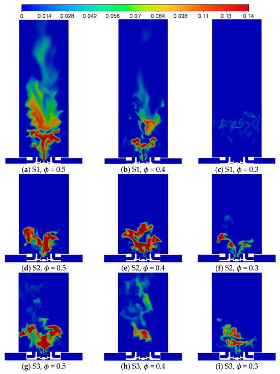
Figure 33.
Swirl number and ϕ impacts on the CO mass fraction: (a) S1, (b) S2, (c) S3, (d) S1, (e) S2, (f) S3, (g) S1, (h) S2, (i) S3.
Figure 34 illustrates the influence of swirl number and equivalence ratio on the OH mass-fraction field, which serves as a key marker of high-temperature reaction zones. For all cases, the OH distribution is strongly correlated with ϕ, with higher equivalence ratios producing more intense and spatially extensive OH regions. At low ϕ, the flame exhibits weak oxidation chemistry, resulting in only small, fragmented OH pockets concentrated near the injector exit. As ϕ increases, a continuous OH layer emerges, indicating a more robust and fully established reaction zone with higher peak temperatures.
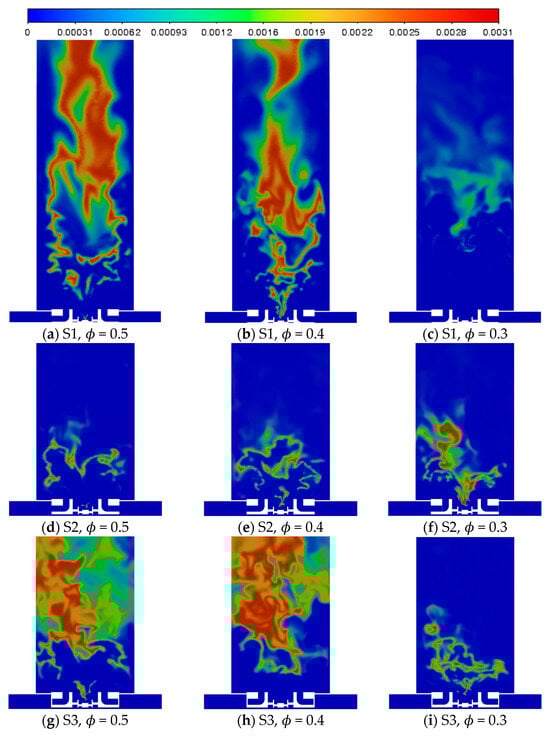
Figure 34.
Swirl number and ϕ impacts on the mass fraction: (a) S1, (b) S2, (c) S3, (d) S1, (e) S2, (f) S3, (g) S1, (h) S2, (i) S3.
Swirl intensity further shapes the topology of the OH field. At low swirl numbers, the OH region remains vertically elongated, with limited radial growth and a narrow flame brush. Increasing the swirl number enhances radial transport and shear-layer entrainment, broadening the OH distribution and promoting a more uniform reaction zone across the combustor cross-section. High-swirl cases exhibit a pronounced recirculation zone that transports OH-rich, high-temperature gases upstream, producing an expanded flame base and improved stabilization. Conversely, in high-swirl, low-ϕ conditions, the OH field becomes highly intermittent, reflecting localized extinction and re-ignition driven by strong mixing. Overall, the results show that ϕ governs OH magnitude, while swirl intensity controls flame spreading, structure, and stabilization through enhanced mixing and recirculating flow.
The present study focuses on carbon monoxide (CO) and carbon dioxide (CO2) emissions under lean operating conditions approaching flame blow-off, where combustion stability becomes increasingly sensitive to operating parameters. In this regime, small variations in equivalence ratio, swirl intensity, and mixing characteristics can lead to pronounced changes in local extinction, incomplete oxidation, and flame anchoring behavior. As a result, CO and CO2 serve as particularly informative markers of combustion completeness and stability near blow-off.
Figure 35 presents the impact of swirl number and ϕ on mass fraction emission characteristics. The low swirl case (S1) shows an increased level of emission at ϕ = 0.5 and 0.4, consistent with the extended combustion zone seen in Figure 32. The high swirl case also shows an increased level of emission at ϕ = 0.5 and 0.4, although this results from flame destabilization. At ϕ = 0.3, S1 experiences a sharp decline in emission due to weak oxidation and extinction of the flame. Case S3 also experienced a reduction, which results from the reduction of overall flame surface compared to the destabilized state at ϕ = 0.5 and 0.4. The S2 case shows an increasing trend of as the ϕ is lowered, indicating that a greater percentage of injected fuel is fully reacting.
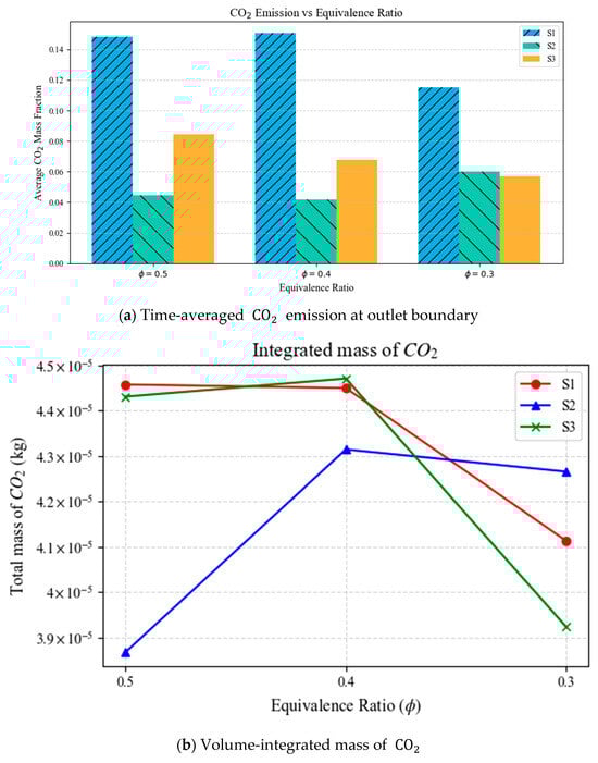
Figure 35.
Swirl number and ϕ impacts on the emission: (a) Time- averaged CO2 emission at outlet boundary, (b) Volume-integrated mass of CO2.
Figure 36 presents the influence of swirl number and ϕ on emission characteristics. For all three swirl configurations (S1, S2, S3) the average outlet mass fraction and volume integrated mass decrease as the ϕ is lowered. The low swirl case (S1) shows a similar emission trend observed for . This combined with the extended reaction zone of S1 indicates that the oxidation of is incomplete at the outlet boundary. S3 at ϕ = 0.5 and 0.4 shows a similar trend to S1, which can be attributed to the incomplete oxidation process due to the extended reaction zone. The S2 case exhibits a decrease in emission, in contrast to the increasing trend observed for .
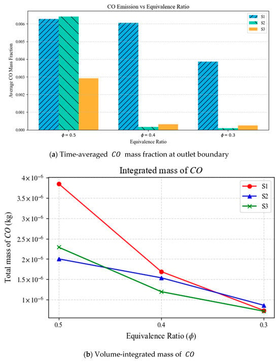
Figure 36.
Swirl number and ϕ impacts on the emission: (a) Time-averaged CO mass fraction Mass Fraction at outlet boundary, (b) Volume-integrated mass of CO.
Comparing the results for S2 and S3 at ϕ = 0.3, where the flame topology is similar, indicates that while increased swirl intensity corresponds to improved mixing, excessive swirl can negatively affect the combustion performance with S3 showing a −5.47% reduction and 156.4% increase in time-averaged outlet mass fraction of and respectively, relative to S2.
Although nitrogen oxides (NOx) emissions remain an important consideration in the design of modern low-emission combustors, their formation is predominantly associated with high-temperature regions and longer residence times, which are less representative of near-blow-off conditions. Consequently, NOx emissions are not addressed in this work, allowing the study to concentrate on the fundamental interactions between operating conditions, flame stability, and CO/CO2 emission behavior in a multi-stage swirl combustor operating close to blow-off.
6. Discussion
The flow behavior in the multi-stage swirl injector exhibits significant dependence on swirl intensity, both in cold-flow and reacting-flow conditions. Comparing these two regimes highlights the interplay between hydrodynamic mechanisms and thermo-chemical effects.
6.1. Hydrodynamic Effects (Cold Flow)
Cold-flow simulations reveal that swirl intensity strongly governs the mean flow organization, recirculation behavior, and vortical structure development. As swirl number increases:
- The injector jet exhibits larger radial deviation and reduced axial penetration, reflecting the redistribution of axial momentum into azimuthal components [29,30].
- The central recirculation zone (CRZ) contracts in both length and width, with the wall stagnation point shifting upstream, consistent with classical vortex breakdown in confined swirling flows [44,46,47,48].
- Shear-layer vortices form along the CRZ boundary, particularly in baseline and high-swirl cases, driven by velocity gradients between the outer swirling jet and the inner recirculated core [49,50,51]. Low-swirl flows, by contrast, develop only a weak stagnation zone upstream of the swirler exit.
- Turbulence kinetic energy (TKE) is concentrated in the outer shear layer for high-swirl jets, forming a ring-like distribution, while low-swirl jets show centerline-concentrated TKE due to weaker jet spreading and swirl-induced shear [47,52,53].
- Vorticity distributions demonstrate that higher swirl produces sharper, more coherent concentric vortical rings, whereas lower swirl results in diffuse, azimuthally distorted structures more susceptible to instabilities [46,47].
Overall, these cold-flow results underscore that swirl number primarily controls CRZ formation, shear-layer turbulence, and vorticity organization, fundamental hydrodynamic mechanisms that influence later flame stabilization and combustion behavior.
6.2. Thermo-Chemical Effects (Reacting Flow)
Introducing combustion substantially modifies the flow and flame structure. Swirl intensity interacts with heat release and equivalence ratio, producing coupled effects on recirculation, flame stabilization, and emissions:
- Low swirl (S1): The flow is largely unaffected by ignition; the CRZ remains compact and robust across equivalence ratios, indicating that geometric swirl dominates over thermal expansion in setting global topology [54,55]. The flame is long and jet-like, confined to the outer shear layer, with a low-temperature core that transitions to a high-temperature region anchored near recirculation zones. Lean conditions (ϕ = 0.3) lead to global extinction.
- Baseline swirl (S2) and high swirl (S3): CRZ stability is more sensitive to ignition and heat release. S2 and S3 show widened jets and downstream shifts in stagnation points due to swirl–combustion coupling. Lean conditions promote CRZ splitting and intermittent recirculation, reflecting heightened susceptibility to vortex breakdown [55,56]. Flame structure is more compact for S2 and S3, with shorter flames resulting from enhanced turbulent mixing.
- Flame unsteadiness and lift-off behavior: Lift-off heights are broadly distributed, indicating fluctuating stabilization. Low swirl yields uniform lift-off, while higher swirl produces multiple preferred positions or unstable distributions under lean conditions.
- Emissions: Moderate swirl (S2) enhances mixing and combustion efficiency, increasing CO2 production while reducing CO. Excessive swirl (S3) destabilizes the flame, reducing overall chemical conversion despite high turbulence [57,58].
6.3. Comparative Insights
The combined analysis highlights the distinctions between purely hydrodynamic and thermo-chemical effects:
- Cold-flow results primarily reflect the influence of swirl on vortex breakdown, CRZ formation, shear-layer turbulence, and vorticity distribution.
- Reacting flows overlay thermal expansion, chemical heat release, and flame–turbulence interactions, which modify CRZ stability, jet spreading, and flame morphology.
- Low swirl maintains stable CRZs under both conditions, while higher swirl intensifies mixing but can destabilize recirculation under lean conditions, demonstrating the critical balance between hydrodynamic control and thermal–chemical coupling in lean direct injection (LDI) combustors.
Together, these findings emphasize that optimal swirl levels must balance robust hydrodynamic recirculation with controlled thermo-chemical effects to achieve stable flame anchoring and efficient combustion.
7. Conclusions
This study examined the influence of swirl intensity on the aerodynamic and reacting-flow behavior of a multi-stage swirl injector operating under both cold- and reacting-flow conditions. The cold-flow results demonstrate that swirl number is the dominant parameter governing flow organization, including CRZ formation, shear-layer development, and vorticity evolution. Increasing swirl redistributes axial momentum into azimuthal components, leading to stronger radial spreading, earlier vortex breakdown, and more coherent recirculation structures. Correspondingly, higher swirl levels produce elevated shear-layer turbulence and sharply defined vorticity rings, while low swirl yields weaker rotational motion and diminished or absent CRZ formation. These trends align with established descriptions of confined swirling jets and highlight the hydrodynamic mechanisms that dictate mixing and flame anchoring in practical combustors.
The LESs of reacting flows employed the dynamic Smagorinsky subgrid model, a reduced chemical mechanism for methane–air combustion, and adiabatic wall boundary conditions. Near the blow-off boundary, the near-swirler mesh resolution and inherent LES modeling constraints may limit the resolution of the smallest turbulent structures. Nevertheless, the main flow and flame dynamics are consistently captured. Consequently, the conclusions are intentionally framed in terms of qualitative mechanisms and trend-based behavior, rather than precise blow-off predictions. Within this clearly defined scope, the numerical results are physically consistent, reproducible, and sufficient to support the conclusions drawn, under the stated assumptions and limitations. Under reacting-flow conditions, thermal expansion strongly couples with swirl-induced aerodynamics, amplifying the differences among swirl cases. The lowest swirl configuration (S1) maintains a stable CRZ across all equivalence ratios, indicating that geometric swirl predominates over heat-release effects in shaping the global topology. In contrast, the baseline and high-swirl cases (S2 and S3) exhibit significant CRZ deformation, intermittent recirculation, and enhanced susceptibility to vortex-breakdown instabilities, particularly under lean operation. These hydrodynamic alterations strongly influence flame stabilization, producing marked differences in jet penetration, flame shape, lift-off behavior, and temperature field organization. At the leanest conditions, S2 and S3 show weakened or intermittent recirculation, consistent with the approach to lean blow-off limits. The emissions analysis further reinforces the role of swirl optimization. Baseline swirl enhances mixing and promotes more complete combustion, reflected in increased major products and reduced CO at leaner conditions. However, excessively high swirl (S3) degrades combustion efficiency, lowering major product formation and increasing incomplete combustion species despite intensified mixing. This indicates the presence of an optimal swirl level beyond which the benefits of enhanced entrainment are offset by CRZ destabilization and flame instability. Overall, the results show that swirl intensity controls the coupled aerodynamics–combustion processes critical to flame stabilization, ignition, and emissions in LDI combustors. Baseline swirl provides the best balance between mixing and stability, while excessive swirl introduces detrimental hydrodynamic instabilities. These insights underscore the importance of tailoring swirl strength in multi-stage injector designs to achieve robust flame stabilization without compromising efficiency or emissions performance. While the numerical results provide insight into flame behavior under varying swirl conditions, they are entirely computational. Future experimental studies are needed to validate the findings and quantify the model’s predictive accuracy.
Author Contributions
Conceptualization, M.I. and B.O.; methodology, M.I. and B.O.; writing—review and editing, M.I. and B.O.; supervision, M.I. All authors have read and agreed to the published version of the manuscript.
Funding
This research received no external funding.
Data Availability Statement
Data is contained within the article.
Conflicts of Interest
The authors declare no conflicts of interest.
References
- Fast Facts on Transportation Greenhouse Gas Emissions. 28 August 2023. Available online: https://www.epa.gov/greenvehicles/fast-facts-transportation-greenhouse-gas-emissions (accessed on 15 July 2025).
- Tacina, R.; Lee, P.; Wey, C. A Lean-Direct-Injection Combustor Using a 9 Point Swirl-Venturi Fuel Injector. ISABE. 2005. Available online: https://api.semanticscholar.org/CorpusID:138994078 (accessed on 20 February 2026).
- Hicks, Y.R.; Heath, C.M.; Anderson, R.C.; Tacina, K.M. Investigations of a combustor using a 9-point swirl-venturi fuel injector: Recent experimental results. In Proceedings of the 20th International Symposium on Air Breathing Engines (ISABE 2011), Gothenburg, Sweden, 12–16 September 2011. [Google Scholar]
- McKinney, R.; Cheung, A.; Sowa, W.; Sepulveda, D. The Pratt and Whitney TALON X low emissions combustor: Revolutionary results with evolutionary technology. In Proceedings of the 45th AIAA Aerospace Sciences Meeting and Exhibit, Reno, NV, USA, 8–11 January 2007; p. 386. [Google Scholar]
- Mongia, H. TAPS: A fourth generation propulsion combustor technology for low emissions. In Proceedings of the AIAA International Air and Space Symposium and Exposition: The Next 100 Years, Dayton, OH, USA, 14–17 July 2003; p. 2657. [Google Scholar]
- Raman, V.; Pitsch, H. Large-eddy simulation of a bluff-body-stabilized non-premixed flame using a recursive filter-refinement procedure. Combust. Flame 2005, 142, 329–347. [Google Scholar] [CrossRef]
- Raman, V.; Pitsch, H.; Fox, R.O. Hybrid large-eddy simulation/Lagrangian filtered-density-function approach for simulating turbulent combustion. Combust. Flame 2005, 143, 56–78. [Google Scholar] [CrossRef]
- di Mare, F.; Jones, W.P.; Menzies, K.R. Large eddy simulation of a model gas turbine combustor. Combust. Flame 2004, 137, 278–294. [Google Scholar] [CrossRef]
- Selle, L.; Lartigue, G.; Poinsot, T.; Koch, R.; Schildmacher, K.-U.; Krebs, W.; Prade, B.; Kaufmann, P.; Veynante, D. Compressible large eddy simulation of turbulent combustion in complex geometry on unstructured meshes. Combust. Flame 2004, 137, 489–505. [Google Scholar] [CrossRef]
- Ge, Y.; Cleary, M.J.; Klimenko, A.Y. A comparative study of Sandia flame series (D–F) using sparse-Lagrangian MMC modelling. Proc. Combust. Inst. 2013, 34, 1325–1332. [Google Scholar] [CrossRef]
- Ihme, M.; Pitsch, H. LES of a Non-Premixed Flame Using an Extended Flamelet/Progress Variable Model. In Proceedings of the 43rd AIAA Aerospace Sciences Meeting and Exhibit, Reno, NV, USA, 10–13 January 2005. [Google Scholar]
- Huang, Y.; Sung, H.-G.; Hsieh, S.-Y.; Yang, V. Large-Eddy Simulation of Combustion Dynamics of Lean-Premixed Swirl-Stabilized Combustor. J. Propuls. Power 2003, 19, 782–794. [Google Scholar] [CrossRef]
- Palies, P. Flow and Flame Mechanisms for Swirl-Stabilized Combustors. Aerospace 2025, 12, 430. [Google Scholar] [CrossRef]
- Ruan, C.; Chen, F.; Yu, T.; Cai, W.; Li, X.; Lu, X. Experimental study on flame/flow dynamics in a multi-nozzle gas turbine model combustor with different swirler configurations. Aerosp. Sci. Technol. 2020, 98, 105692. [Google Scholar] [CrossRef]
- Zhao, Q.; Yang, J.; Liu, C.; Liu, F.; Wang, S.; Mu, Y.; Xu, G.; Zhu, J. Experimental investigation on lean blowout dynamics of spray flame in a multi-swirl staged combustor. Therm. Sci. Eng. Prog. 2023, 37, 101551. [Google Scholar]
- Liu, H.; Xu, C.; Le, J. Large eddy simulation of lean blow-off in swirl-stabilized flame with subgrid dissipation concept. Combust. Flame 2024, 267, 113596. [Google Scholar] [CrossRef]
- Ma, G.; Zhao, G.; Sun, M.; Zhao, C.; Li, F.; Zhu, J.; Yang, Y. The shock-assisted self-ignition behavior and combustion transition mechanisms in a Mach 8 scramjet combustor. Combust. Flame 2026, 285, 114721. [Google Scholar]
- Zhao, C.; Zhao, G.; Li, F.; Liu, M.; Ma, G.; Feng, S.; Sun, M. Application of Throat Compensation Based on Scale Effects of the Scramjet Combustor. AIAA J. 2025, 63, 4357–4373. [Google Scholar] [CrossRef]
- Zhao, Q.; Yang, J.; Liu, C.; Liu, F.; Wang, S.; Mu, Y.; Xu, G.; Zhu, J. Lean blowout characteristics of spray flame in a multi-swirl staged combustor under different fuel decreasing rates. Chin. J. Aeronaut. 2022, 35, 130–143. [Google Scholar] [CrossRef]
- Lin, J.; Bao, M.; Zhang, F.; Zhang, Y.; Yang, J. Numerical and experimental investigation of a non-premixed double swirl combustor. Energies 2022, 15, 458. [Google Scholar] [CrossRef]
- Liu, Z.; Shi, X.; Zhang, Y.; Yang, X.; Han, S.; Fang, J.; Lian, T.; Li, W.; Li, Y. Characterizing lean blowout dynamics of DME/air premixed swirl flames in a gas turbine model combustor with and without confinement. Aerosp. Sci. Technol. 2024, 152, 109360. [Google Scholar] [CrossRef]
- Vashahi, F.; Rezaei, S.; Dafsari, R.A.; Lee, J. Sensitivity analysis of the vane length and passage width for a radial type swirler employed in a triple swirler configuration. Theor. Appl. Mech. Lett. 2019, 9, 363–375. [Google Scholar] [CrossRef]
- Kemenov, K.A.; Wang, H.; Pope, S.B. Turbulence Resolution Scale Dependence in Large-Eddy Simulations of a Jet Flame. Flow Turbul. Combust. 2012, 88, 529–561. [Google Scholar] [CrossRef]
- Pope, S.B. Turbulent Flows; Cambridge University Press: Cambridge, UK, 2000. [Google Scholar]
- Sagaut, P. Large Eddy Simulation for Incompressible Flows: An Introduction, 3rd ed.; Springer: Berlin, Germany, 2006. [Google Scholar]
- Moin, P.; Mahesh, K. Direct Numerical Simulation: A Tool in Turbulence Research. Annu. Rev. Fluid Mech. 1998, 30, 539–578. [Google Scholar] [CrossRef]
- Pitsch, H. Large-Eddy Simulation of Turbulent Combustion. Annu. Rev. Fluid Mech. 2006, 38, 453–482. [Google Scholar] [CrossRef]
- Gicquel, L.Y.M.; Staffelbach, G.; Poinsot, T. Large Eddy Simulations of gaseous flames in gas turbine combustion chambers. Prog. Energy Combust. Sci. 2012, 38, 782–817. [Google Scholar] [CrossRef]
- Celik, I.; Ghia, U.; Roache, P.; Freitas, C. Procedure for Estimation and Reporting of Uncertainty Due to Discretization in CFD Applications. J. Fluids Eng. 2008, 130, 078001. [Google Scholar] [CrossRef]
- Qiao, Z. On the Robustness and Accuracy of Large-Eddy Simulation: Assessment Using Pope’s LES Quality Criterion. Phys. Fluids 2023, 35, 085120. [Google Scholar] [CrossRef]
- Spalart, P.R.; Strelets, M.K.; Travin, A. Detached-Eddy Simulation of Complex Turbulent Flows. In Proceedings of the AIAA 33rd Aerospace Sciences Meeting and Exhibit, Reno, NV, USA, 9–12 January 1995. AIAA Paper 95-0152. [Google Scholar]
- Xu, R.; Wang, K.; Banerjee, S.; Shao, J.; Parise, T.; Zhu, Y.; Wang, S.; Movaghar, A.; Lee, D.J.; Zhao, R. A physics-based approach to modeling real-fuel combustion chemistry–II. Reaction kinetic models of jet and rocket fuels. Combust. Flame 2018, 193, 520–537. [Google Scholar] [CrossRef]
- Yuan, R.; Kariuki, J.; Mastorakos, E. Measurements in swirling spray flames at blow-off. Int. J. Spray Combust. Dyn. 2018, 10, 185–210. [Google Scholar] [CrossRef]
- Tyliszczak, A.; Cavaliere, D.E.; Mastorakos, E. LES/CMC of blow-off in a liquid fueled swirl burner. Flow Turbul. Combust. 2014, 92, 237–267. [Google Scholar] [CrossRef]
- Elasrag, H.; Li, S. Investigation of extension and reignition events using the flamelet generated manifold model, GT2018-75420. In Proceedings of the ASME Turbo Expo 2018 Turbomachinery Technical Conference and Exposition GT2018, Oslo, Norway, 11–15 June 2018. [Google Scholar]
- Boudier, G.; Gicquel, L.Y.M.; Poinsot, T.J. Effects of mesh resolution on large eddy simulation of reacting flows in complex geometry combustors. Combust. Flame 2008, 155, 196–214. [Google Scholar] [CrossRef]
- Yee, H.C.; Sweby, P.K. Dynamics of Numerics and Spurious Behaviors in CFD Computations; NASA/USRA Technical Report; RIACS-TR-97.06; NASA: Washington, DC, USA, 1997. [Google Scholar]
- Ekaterinaris, J.A. High-order accurate, low numerical diffusion methods for aerodynamics. Prog. Aerosp. Sci. 2005, 41, 192–300. [Google Scholar] [CrossRef]
- Foale, J.M. Simulating Extinction and Blow-Off in Kerosene Swirl Spray Flames. Ph.D. Thesis, University of Cambridge, Cambridge, UK, 2022. [Google Scholar]
- Versteeg, H.K.; Malalasekera, W. An Introduction to Computational Fluid Dynamics: The Finite Volume Method, 2nd ed.; Pearson: London, UK, 2007. [Google Scholar]
- Ansys. Ansys Fluid Dynamics Verification Manual; ANSYS, Inc.: Canonsburg, PA, USA, 2025. [Google Scholar]
- Gupta, A.K.; Lilley, D.G.; Syred, N. Swirl Flows; Abacus Press: Kent, UK, 1984. [Google Scholar]
- Lefebvre, A.H.; Ballal, D.R. Gas Turbine Combustion: Alternative Fuels and Emissions, 3rd ed.; CRC Press: Boca Raton, FL, USA, 2010. [Google Scholar]
- Syred, N. A review of oscillation mechanisms and the role of the precessing vortex core (PVC) in swirl combustion systems. Prog. Energy Combust. Sci. 2006, 32, 93–161. [Google Scholar] [CrossRef]
- Huang, Y.; Yang, V. Dynamics and Stability of Lean-Premixed Swirl-Stabilized Combustion. Prog. Energy Combust. Sci. 2009, 35, 293–364. [Google Scholar] [CrossRef]
- Weber, R. Vortex Breakdown in Swirling Flames. AIAA J. 1983, 21, 962–963. [Google Scholar]
- Li, Y.; Gutmark, E.J. Flow Structure in a Swirl-Stabilized Combustor. AIAA J. 2006, 44, 1734–1745. [Google Scholar]
- Koylu, U.O.; Mishra, D.P. Characterization of Flow Fields in a Multi-Swirl Injector. J. Propuls. Power 2012, 28, 365–375. [Google Scholar]
- Tacina, R.; Smith, C.E. Swirl Cup Combustor Aerodynamics. J. Propuls. Power 1988, 4, 123–130. [Google Scholar]
- Gilletta, A.; Bonamy, C.; Robert, M.; Chauchat, J. Assessment of hybrid RANS/LES models for the prediction of the flow and scour around a wall-mounted cylinder. Adv. Water Resour. 2025, 199, 104934. [Google Scholar] [CrossRef]
- Menter, F.R. Stress-Blended Eddy Simulation (SBES)-A New Paradigm in Hybrid RANS-LES Modeling. In Proceedings of the 6th Symposium on Hybrid RANS-LES Methods, Strasbourg, France, 26–28 September 2016; Notes on Numerical Fluid Mechanics and Multidisciplinary Design; Springer Science and Business Media LLC: Cham, Switzerland, 2018; Volume 137. [Google Scholar]
- Spalart, P.R.; Jou, W.-H.; Strelets, M.; Allmaras, S.R. Comments on the Feasibility of LES for Wings, and on a Hybrid RANS/LES Approach. In Advances in DNS/LES, 1st ed.; Greyden Press: Columbus, OH, USA, 1997; pp. 4–8. [Google Scholar]
- Fröhlich, J.; von Terzi, D. Hybrid LES/RANS Methods for the Simulation of Turbulent Flows. Prog. Aerosp. Sci. 2008, 44, 349–377. [Google Scholar] [CrossRef]
- Sagaut, P. Large Eddy Simulation for Incompressible Flows, 3rd ed.; Springer: New York, NY, USA, 2006. [Google Scholar]
- Shur, M.L.; Spalart, P.R.; Strelets, M.K.; Travin, A.K. A Hybrid RANS–LES Approach with Delayed-DES and Wall-Modelled LES Capabilities. Int. J. Heat Fluid Flow 2008, 29, 1638–1649. [Google Scholar] [CrossRef]
- Poinsot, T.; Veynante, D. Theoretical and Numerical Combustion, 3rd ed.; Edwards: Philadelphia, PA, USA, 2012. [Google Scholar]
- Chaouat, B. The State of the Art of Hybrid RANS/LES Modeling for the Simulation of Turbulent Flows. Flow Turbul. Combust. 2017, 99, 279–327. [Google Scholar] [CrossRef] [PubMed]
- Gritskevich, M.S.; Garbaruk, A.V.; Schütze, J.; Menter, F.R. Development of DDES and IDDES Formulations for the k–ω Shear Stress Transport Model. Flow Turbul. Combust. 2012, 88, 431–449. [Google Scholar] [CrossRef]
- Lia, R.; Zhaob, L.; Geb, N.; Gaob, L.; Nia, M. Grid Resolution Requirements and Assessment in Hybrid RANS–LES Simulations. Eng. Appl. Comput. Fluid Mech. 2022, 16, 279–295. [Google Scholar]
- Steinberg, A.M.; Driscoll, J.F. Lean Blowout Mechanisms in Swirl-Stabilized Flames. AIAA J. 2009, 47, 1802–1814. [Google Scholar]
- Shanbhogue, S.J.; Husain, S.; Lieuwen, T.C. Lean Blowoff of Bluff-Body Stabilized Flames: Scaling and Dynamics. Prog. Energy Combust. Sci. 2009, 35, 98–120. [Google Scholar] [CrossRef]
- Liang, Y.; Juniper, M.P.; Morgans, A.S. Vortex Breakdown and Combustion-Induced Instabilities in Swirling Flames. J. Fluid Mech. 2013, 725, 492–521. [Google Scholar]
- Lieuwen, T. Unsteady Combustor Physics; Cambridge University Press: New York, NY, USA, 2012. [Google Scholar]
- Kariuki, J.; Balusamy, S.; Rajasekaran, V. Influence of Heat Release on Vortex Breakdown in Swirl Burners. Combust. Flame 2016, 168, 23–36. [Google Scholar]
- Delabroy, O.; Bellet, F.; Mariette, F. Impact of Swirl Intensity on Flow Stability and Emissions in Lean Premixed Burners. In Proceedings of the ASME Turbo Expo, Düsseldorf, Germany, 16–20 June 2014. GT2014-26188. [Google Scholar]
- Zeng, C.; Sun, Z.; Huang, Z.; Yang, V. Swirl Effects on Emission Characteristics of Lean Direct Injection Combustors. AIAA J. 2016, 54, 3544–3557. [Google Scholar]


Disclaimer/Publisher’s Note: The statements, opinions and data contained in all publications are solely those of the individual author(s) and contributor(s) and not of MDPI and/or the editor(s). MDPI and/or the editor(s) disclaim responsibility for any injury to people or property resulting from any ideas, methods, instructions or products referred to in the content. |
© 2026 by the authors. Licensee MDPI, Basel, Switzerland. This article is an open access article distributed under the terms and conditions of the Creative Commons Attribution (CC BY) license.