Abstract
Satellite pointing mechanisms for earth observation require ultra-low speed scanning (approximately ) and precise variable-speed compensation. However, traditional Field-Oriented Control (FOC) suffers from significant velocity bias and instability under these conditions. To address these issues, this paper proposes a position-loop-based speed control scheme integrated with a variable structure control strategy. By substituting the speed command with a position loop, the proposed method effectively suppresses steady-state velocity bias, while the variable structure strategy mitigates fluctuations during variable-speed motion. Experimental results indicate that, compared to traditional FOC, the proposed method reduces velocity bias error by over during uniform tracking and decreases the amplitude of velocity fluctuations by more than in variable-speed scenarios. This strategy significantly enhances the control precision of satellite pointing mechanisms and improves on-orbit imaging compensation accuracy.
1. Introduction
High-precision pointing mechanisms serve as the cornerstone of satellite remote sensing and inter-satellite optical communication missions [1,2,3]. These electromechanical systems operate under paradoxical requirements: they must sustain ultra-stable scanning at extremely low speeds (often sub-degree per second, e.g., ) while retaining the agility to execute rapid variable-speed maneuvers for attitude compensation [4,5]. For instance, in space optical communication terminals, velocity stability is strictly bounded within 2.5% to prevent link outages. However, satisfying such stringent specifications presents a formidable challenge for traditional Permanent Magnet Synchronous Motor (PMSM) drives governed by Field-Oriented Control (FOC).
The primary obstacle stems from the inherent limitations of velocity estimation in the absence of high-speed tachometers. In standard FOC schemes, angular velocity is derived by differentiating discrete position signals from optical encoders [6,7]. At ultra-low speeds, the quantization noise becomes dominant. Although cascading rolling average filters can mitigate this noise, they inevitably introduce a low-frequency phase lag and gain attenuation [8]. As mathematically elucidated in Section 2 of this paper, this spectral deficiency renders the speed loop insensitive to static friction disturbances, precipitating a phenomenon known as “velocity bias”—a persistent steady-state error that degrades imaging quality [9,10,11,12].
A secondary, yet equally critical challenge arises during variable-speed tracking driven by discrete guidance commands. In orbit, reference trajectories are typically updated at a low frequency (e.g., 40 Hz) by the satellite’s attitude control system. When these discrete position waypoints are differentiated to generate speed references, the resulting discontinuities act as step excitations to the high-bandwidth speed loop, inducing severe ripples and acoustic noise.
To address these issues, control strategies of varying complexity have been investigated. Observer-based methods, such as Extended State Observers (ESOs) and Disturbance Observers (DOBs), are widely advocated in terrestrial robotics to reconstruct velocity and estimate friction [13,14,15,16]. Similarly, advanced robust controllers like Sliding Mode Control (SMC) and control have demonstrated theoretical efficacy in suppressing nonlinearities [17,18,19,20,21]. While these approaches offer high performance, their implementation on satellite platforms faces rigorous constraints. High-order observers impose substantial computational burdens on radiation-hardened processors (typically DSPs or FPGAs with limited floating-point capability). Moreover, the parameter sensitivity of adaptive algorithms introduces reliability risks during long-term on-orbit operation [22,23,24]. Consequently, an “observer-free” architecture that achieves high precision through structural reconfiguration rather than algorithmic complexity is highly desirable for aerospace engineering.
The existing literature has explored the integration of position loops into speed control or the application of Variable Structure Control (VSC) to PMSMs [25,26,27]. However, few studies have addressed the specific coupling between the discrete position update rate and the continuous speed loop dynamics in the context of ultra-low speed satellite pointing. Direct application of generic VSC often leads to chattering, which is unacceptable for jitter-sensitive optical payloads [28,29].
Bridging this gap, this paper proposes a high-reliability, moderate-computational-cost control strategy tailored for satellite pointing mechanisms. The contributions are twofold:
- Position-Loop-Based Speed Control Architecture: By reformulating the speed regulation task as a high-precision position tracking problem, the scheme leverages the infinite DC gain of the position integrator. This structurally eliminates the steady-state velocity bias caused by estimator attenuation without requiring auxiliary friction observers.
- Discrete-Synchronized Variable Structure Strategy: Recognizing that velocity ripples originate from the discrete nature of command updates, we introduce a gain scheduling law that is strictly synchronized with the position update cycle. This mechanism dynamically modulates the control stiffness to reconcile transient tracking speed with steady-state convergence, effectively suppressing ripples induced by command discretization.
The proposed methodology is validated on a flight-model prototype. Experimental results demonstrate that the strategy significantly enhances both steady-state precision and dynamic stability compared to traditional FOC, offering a robust solution ready for engineering deployment. The remainder of this paper is organized as follows: Section 2 presents the theoretical analysis of the velocity bias mechanism and the proposed control scheme; Section 3 describes the experimental platform and results; and Section 4 concludes the paper.
2. Theoretical Analysis
2.1. Mechanism of Velocity Bias Error in Speed Loop Control Under Ultra-Low Speed Conditions and Improvement Methods
2.1.1. Limitations of Traditional FOC Scheme
In conventional Field-Oriented Control (FOC) strategies, rotor velocity is typically estimated indirectly via the differentiation of discrete encoder position signals. Under ultra-low speed conditions, to mitigate quantization noise and enhance estimation accuracy, a two-stage rolling average difference algorithm is commonly introduced. While this structure effectively improves the resolution of speed measurement at extremely low speeds, its inherent spectral characteristics introduce significant low-frequency gain attenuation. This attenuation precipitates a steady-state velocity bias during constant low-speed tracking.
Mathematically, the signal processing chain can be formalized as follows. Let denote the incremental position at sampling instance k, calculated as . The rolling average over a window N is given by . Subsequently, the difference is taken with a delay of M samples: . The final estimated velocity is derived as:
where is the sampling period. Taking the Z-transform of the difference equations, the discrete transfer function from the actual angular velocity to the estimated value is derived as:
Analyzing the frequency response of Equation (2) reveals a critical deficiency: the gain approaches zero as the frequency [30,31]. In the low-frequency domain (), the estimator exhibits strong compression, effectively behaving as a “differential-type” measurement rather than a proportional one. Consequently, the speed loop receives attenuated DC velocity feedback during constant speed operations, rendering the closed-loop system insensitive to static errors.
To quantify this bias, we incorporate the electromechanical dynamics of the motor-load system [32]. The torque balance equation is governed by:
where represents the equivalent inertia, is the angular acceleration, B is the viscous friction coefficient, and denotes the Coulomb friction torque.
Assuming the inner current loop is ideal due to its high bandwidth, the speed loop closed-loop system with a PI controller () can be modeled. The steady-state speed under a constant command is determined by the DC gain of the forward path and the feedback path . At steady state (), the integral action dominates, but the feedback attenuation persists. The steady-state equilibrium equation is:
The controller output, driven by the error , generates the current:
where is the equivalent static gain of the PI controller. Combining (4) and (5), we solve for :
Defining the velocity bias error as , and simplifying by grouping the loop gain terms, we obtain:
Equation (7) explicitly demonstrates that the traditional FOC speed loop cannot eliminate the steady-state error induced by friction torque () and viscous damping (B) due to the measurement attenuation coefficient . This theoretical deduction elucidates the “velocity bias” phenomenon observed in high-precision pointing tasks, necessitating a fundamental structural reconfiguration.
2.1.2. Position-Loop-Based Speed Control Scheme
To eliminate the steady-state error inherent in the traditional speed loop, this study proposes a Position-Loop-Based Speed Control architecture. The core innovation lies in reformulating the speed regulation task as a high-precision position tracking problem, thereby utilizing the infinite DC gain of the position integrator to actively reject disturbances. The proposed control structure is illustrated in Figure 1.

Figure 1.
Block diagram of the Position-Loop-Based Speed Control scheme.
Specifically, for uniform speed tracking tasks, the reference trajectory is not a constant speed command but a time-dependent position ramp , synthesized as:
Defining the position tracking error as , kinematic consistency implies that the derivative of the error is proportional to the velocity deviation, i.e., . The control law is then synthesized by closing the loop on position deviation:
where serves as the feedforward velocity term. The integral term is pivotal: it automatically accumulates the compensation torque required to counteract the friction torque exactly when the position error converges to steady state.
Substituting (9) into the low-frequency linearized model of the speed loop (), the characteristic equation of the closed-loop error dynamics becomes:
According to the Final Value Theorem, for a stable system, the steady-state error satisfies and . Consequently, the actual speed converges exactly to the demand speed:
This derivation proves that introducing the position loop theoretically eliminates steady-state velocity bias. However, in practical variable-speed scenarios, the position command is updated discretely. The mismatch between the discrete position update rate and the continuous speed loop dynamics can induce tracking ripples. This limitation motivates the variable structure design presented in the subsequent section.
2.2. Improved Design of Variable Structure Control Based on Position-Loop Speed Control Scheme
2.2.1. Causes of Velocity Fluctuations in Position-Loop Variable Speed Control
In digital control implementations, the position command is updated at a fixed period . The Position-Loop-Based Speed Control generates a velocity reference based on the discrete position error. The speed loop, operating at a faster sampling rate with time constant , treats this reference as a step input within each position cycle .
The dynamic mismatch arises when the command update period is comparable to the speed loop time constant (). A recurrence relation for the velocity lag error can be derived as:
Equation (12) indicates that any change in the reference command curvature () injects an excitation into the speed channel. If the speed loop bandwidth is fixed, this excitation cannot be fully attenuated within a single period , leading to velocity overshoot and oscillation. This phenomenon is qualitatively illustrated in Figure 2, where the actual speed curve exhibits distinct spikes at the instances of command updates, failing to converge before the next cycle begins. To suppress these fluctuations, it is necessary to dynamically adjust the control stiffness during the transient phase.

Figure 2.
Schematic diagram of speed response under position-loop based variable speed control.
2.2.2. Improved Design of Variable Structure Control
To resolve the conflict between fast transient tracking and oscillation suppression, a Variable Structure Control (VSC) strategy based on gain scheduling is proposed. Let be the ratio of position loop period to speed loop period. We introduce a sub-step index within each position update cycle. The proportional gain of the speed loop, , is scheduled to follow a geometric progression:
where is the baseline gain tuned for uniform speed, and is a decay factor (set to 0.9 in this study) [33,34]. This scheduling law enforces a “high-damping to high-stiffness” transition: at the beginning of the cycle (), the gain is low to suppress the initial step excitation; as the cycle progresses (), the gain increases to ensure convergence of the tracking error.
Although the proposed strategy involves a time-varying gain, the stability of the closed-loop system can be guaranteed by examining the contractivity of the error dynamics. The error propagation within a single sub-step is governed by:
where represents the discrete pole location. Since the gain is always positive, the pole remains strictly within the unit circle, ensuring that the homogeneous part of the system is strictly contractive.
Furthermore, the residual error at the end of the position period is determined by the product of the decay rates:
The geometric scheduling allocates higher convergence rates to the latter part of the period. As depicted in Figure 3, the implementation of this variable structure strategy effectively smoothens the speed response. The initial spikes are significantly dampened compared to Figure 2, and the speed trajectory converges smoothly within each update cycle. This design effectively bounds the velocity fluctuation tube, fulfilling the Bounded-Input Bounded-Output (BIBO) stability criterion without compromising steady-state precision.

Figure 3.
Schematic diagram of speed response with variable structure control enabled.
3. Experimental Verification
3.1. Experimental Platform and Test Scheme
To validate the efficacy of the proposed control strategies, experiments were conducted on a high-precision two-axis satellite pointing mechanism prototype (Figure 4). The experimental setup consists of an azimuth axis and an elevation axis, both driven by direct-drive Permanent Magnet Synchronous Motors (PMSMs) [35]. The system parameters are detailed as follows: the azimuth axis possesses a rotor inertia of 0.086 kg · m2 and a load inertia of 0.43 kg · m2, with a maximum output torque of 2 Nm; the elevation axis has a rotor inertia of 0.011 kg · m2 and a load inertia of 0.056 kg · m2.

Figure 4.
Prototype of the two-axis pointing mechanism (Structural components).
High-resolution angular position feedback is critical for ultra-low speed control. The platform employs a 24-bit absolute photoelectric encoder, providing a resolution of . This resolution is sufficient to meet the control requirements for the target scanning speed of . The control algorithms are implemented on a heterogeneous computing architecture (Figure 5) comprising a TI TMS320C6701 DSP for algorithm execution (10 kHz interrupt frequency) and an FPGA for high-speed I/O processing [36,37]. The current loop operates at 10 kHz, ensuring a high-bandwidth torque response, while the speed and position loops operate at 400 Hz and 40 Hz, respectively.

Figure 5.
Prototype of the two-axis pointing mechanism (Electrical control box).
Two distinct experimental scenarios were designed to evaluate steady-state precision and dynamic stability:
- Constant Low-Speed Tracking: Evaluating the elimination of velocity bias at a constant speed of in both forward and reverse directions.
- Variable-Speed Profile Tracking: Assessing the suppression of velocity fluctuations under simulated on-orbit scanning trajectories, characterized by frequent speed reference changes.
3.2. Steady-State Performance Analysis Under Ultra-Low Speed
In the experiments, the two-stage rolling differential windows M and N were set to 9, and the speed sampling period was 0.1 ms. The equivalent viscous friction coefficient for the azimuth axis, , was 50 N · m · s/rad, and for the elevation axis, , was 10 N · m · s/rad. The Coulomb friction torques were set to N · m and N · m, respectively. Based on the system identification, the closed-loop natural frequencies of the speed loops for the two axes were obtained as and . Substituting these values into the estimator transfer function, the low-frequency gains of the speed measurement link were calculated as and , respectively. The equivalent static loop gains (product of torque constant and controller gain) were determined to be and .
Under the condition of a command speed , substituting the aforementioned parameters into the theoretical analysis Equation (7), the theoretical steady-state velocity bias errors for the two axes under traditional speed loop control were calculated as follows:
The calculation results indicate that under the current experimental conditions, the theoretical steady-state velocity bias errors for the azimuth and elevation axes are approximately and , respectively. This means the actual steady-state speed is slightly higher than the target speed, and the magnitude of this deviation is consistent with the experimental measurement results shown in the subsequent figures [38,39].
3.2.1. Forward Rotation Test
Figure 6 illustrates the speed response of the azimuth and elevation axes during forward rotation. Under the traditional speed loop control (orange line), a persistent steady-state velocity bias is observed. The actual speed consistently lags behind the command, with an average error of approximately for the azimuth axis. This confirms the theoretical prediction in Equation (7) that the weak low-frequency gain of the speed estimator fails to fully compensate for viscous and Coulomb friction.
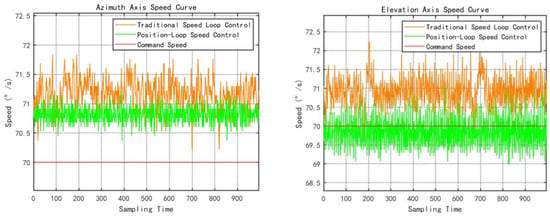
Figure 6.
Speed response curves of the two axes during forward rotation.
In contrast, the proposed position-loop scheme (green line) exhibits superior tracking accuracy. By integrating the position error, the controller effectively estimates the friction torque , forcing the steady-state speed to converge to the reference value.
3.2.2. Reverse Rotation and Symmetry Validation
To further verify the robustness of the proposed method against direction-dependent disturbances (e.g., the sign reversal of Coulomb friction), reverse rotation tests were conducted. As shown in Figure 7, the traditional method exhibits a positive bias during reverse motion, which is symmetrical to the forward case. This indicates that the uncompensated friction torque always opposes the motion direction.
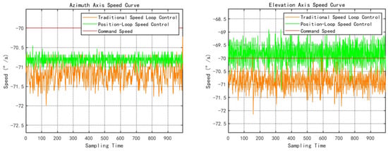
Figure 7.
Speed response curves of the two axes during reverse rotation.
Crucially, the proposed method maintains near-zero steady-state error in the reverse direction as well. This result confirms that the integral action within the position loop correctly adapts to the sign change in the nonlinear friction (), ensuring consistent performance regardless of rotation direction.
3.2.3. Quantitative Summary of Steady-State Performance
To provide a rigorous evaluation, the key performance metrics—Mean Velocity Bias () and Root Mean Square Error (RMSE)—are summarized in Table 1. As indicated in the table, the proposed method reduces the velocity bias by over 89% across all test conditions. The significant reduction in RMSE further demonstrates that the closed-loop stiffness is enhanced, effectively rejecting low-frequency friction disturbances.

Table 1.
Quantitative comparison of steady-state performance under constant speed.
As indicated in Table 1, the proposed method reduces the velocity bias by over across all test conditions. The significant reduction in RMSE further demonstrates that the closed-loop stiffness is enhanced, effectively rejecting low-frequency friction disturbances.
3.3. Dynamic Performance Analysis Under Variable Speed Trajectories
The variable speed trajectory tracking experiment further highlights the advantages of the variable structure control strategy proposed in this paper. Experimental data were collected under “Left Track,” “Middle Track,” and “Right Track” scenarios at two different ground speeds (115 and 230). The target speed sequences and measured speed sequences for both the azimuth and elevation axes were compared, and indicators such as maximum speed deviation, speed standard deviation, and Root Mean Square Error (RMSE) of speed were calculated. By comparing the results with and without variable structure control enabled, a significant improvement in speed tracking indicators can be clearly observed.
3.3.1. Suppression of Discrete Ripples
Figure 8, Figure 9, Figure 10, Figure 11, Figure 12 and Figure 13 depict the comparative speed responses corresponding to six distinct trajectory profiles. When the Variable Structure Control is disabled (orange line), the speed response exhibits distinct “spikes” and oscillations under variable-speed position command conditions. This aligns with the analysis in Section 2.2.1, where the mismatch between the discrete position update period () and the speed loop bandwidth () induces step excitations.
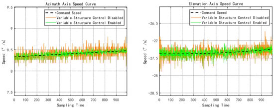
Figure 8.
Speed curves of the two axes for the Left Track trajectory (Ground Speed: 115).
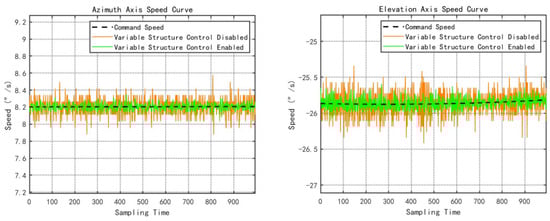
Figure 9.
Speed curves of the two axes for the Left Track trajectory (Ground Speed: 230).
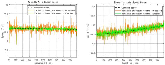
Figure 10.
Speed curves of the two axes for the Middle Track trajectory (Ground Speed: 115).

Figure 11.
Speed curves of the two axes for the Middle Track trajectory (Ground Speed: 230).
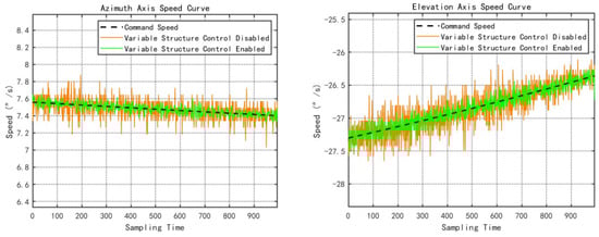
Figure 12.
Speed curves of the two axes for the Right Track trajectory (Ground Speed: 115).
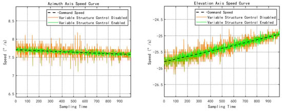
Figure 13.
Speed curves of the two axes for the Right Track trajectory (Ground Speed: 230).
Upon enabling the VSC strategy (green line), these ripples are significantly attenuated. The gain scheduling mechanism—starting with high damping (low gain) to suppress the initial shock and transitioning to high stiffness (high gain) to eliminate residual error—results in a much smoother transition during speed changes.
3.3.2. Quantitative Summary of Dynamic Performance
To quantify the improvement in dynamic stability, statistical metrics including Maximum Deviation (), Standard Deviation (), and RMSE were calculated for six different trajectory sets. The consolidated results are presented in Table 2.
Table 2.
Quantitative comparison of dynamic performance under variable speed trajectories.
The data reveals a consistent performance enhancement. For the high-inertia azimuth axis, the VSC strategy reduces the maximum speed deviation by approximately 69% and the RMSE by 61% on average. For the elevation axis, although the baseline fluctuations were smaller due to lower inertia, the VSC still contributed to a significant reduction in error metrics. These results experimentally validate the contractivity analysis presented in Section 2.2.2, confirming that the variable structure gain scheduling effectively bounds the error dynamics within a narrower tube.
4. Conclusions
This paper addresses the challenges of low-speed and variable-speed control for high-precision satellite pointing mechanisms by proposing and verifying an improved control strategy. The main contributions and conclusions are as follows:
- Position-Loop-Based Speed Control Scheme: By utilizing the outer position loop to generate speed references and performing closed-loop position control, zero steady-state error tracking for constant low-speed motion is achieved. Experimental results indicate that under the ultra-low uniform speed condition of 70 arc-seconds per second, this scheme reduces the velocity bias error generated by traditional FOC speed loop control by more than 30%, significantly enhancing steady-speed precision.
- Variable Structure Speed Loop Control Strategy: By implementing segmental scheduling of the speed loop PID gains within the intervals of position command updates, the speed response is optimized to transition from strong damping to fast tracking and finally to smooth convergence. Compared with fixed-gain control, the amplitude of motor speed fluctuations is reduced by more than 40% during complex variable-speed trajectory tracking, and overshoot is effectively suppressed, demonstrating the effectiveness of this strategy in improving the stability of variable-speed motion.
- Engineering Significance: The proposed method provides a simple and efficient solution for achieving high-precision, low-speed, and variable-speed control for satellite pointing mechanisms on-orbit. Without increasing additional sensors or hardware complexity, the strict requirements for satellite earth observation imaging compensation can be met solely through control algorithm improvements. This holds significant engineering value for resource-constrained small satellite platforms and can enhance on-orbit imaging quality and mission reliability.
- Future Work: To further enhance system performance and robustness, future research will consider introducing intelligent adaptive algorithms, such as online parameter self-tuning or model reference adaptive control, to allow the controller to automatically adjust gains according to operating conditions and adapt to environmental changes like temperature variations and wear [40]. Meanwhile, combining friction torque observation and compensation, as well as exploring higher-resolution sensing and filtering technologies, are also directions worth investigating. Through these efforts, the ultra-low speed and high-precision control of satellite pointing mechanisms is expected to reach a higher level, meeting the requirements of more stringent future space optical missions [41].
Author Contributions
Conceptualization, C.H., H.L. and D.H.; methodology, C.H. and H.L.; software, C.H., H.L., J.C. and Z.F.; validation, C.H., H.L. and D.H.; formal analysis, C.H., H.L., J.C. and Z.F.; investigation, C.H., H.L., J.C., Z.F. and D.H.; data curation, C.H., H.L., J.C. and Z.F.; writing—original draft preparation, C.H. and H.L.; writing—review and editing, C.H. and X.Z.; supervision, H.L., J.J., J.S., X.Z., X.W. and X.L.; project administration, H.L., J.J., J.S., X.Z., X.W. and X.L.; funding acquisition, J.J., J.S., X.Z., X.W. and X.L. All authors have read and agreed to the published version of the manuscript.
Funding
This research was funded by the National Key R&D Program of China, grant numbers 2022YFB3904805 and 2024YFC2206900. The APC was funded by the Hangzhou Institute for Advanced Study, University of Chinese Academy of Sciences.
Data Availability Statement
The data presented in this study are not publicly available due to strict confidentiality restrictions involved in the aerospace project.
Conflicts of Interest
The authors declare no conflict of interest.
References
- Dhruv; Kaushal, H. A Review of Pointing Modules and Gimbal Systems for Free-Space Optical Communication in Non-Terrestrial Platforms. Photonics 2025, 12, 1001. [Google Scholar] [CrossRef]
- Sun, S.W.; Noh, J.H. End-to-End Performance Analysis of CCSDS O3K Optical Communication System Under Atmospheric Turbulence and Pointing Errors. Aerospace 2025, 12, 869. [Google Scholar] [CrossRef]
- Li, Z.; Guo, J.; Qin, T.; Wang, J.; Peng, J.; Wu, Y.; Jing, Z.; Zhang, H.; Hou, J.; Qi, B. Investigation on Micro-Vibration Test and Image Stabilization of a High-Precision Space Optical Payload. Appl. Sci. 2025, 15, 1596. [Google Scholar] [CrossRef]
- Raffa, S. Spacecraft Micro-Vibrations Analysis for Optical Communication Payloads. Ph.D. Thesis, Politecnico di Torino, Turin, Italy, 2020. [Google Scholar]
- Liu, X.; Li, X.; Deng, Z.; Sun, H. Optimization and Verification of Acquisition Time Method Based on a Data-Driven Model for Laser Inter-Satellite Links. Electronics 2025, 14, 2854. [Google Scholar] [CrossRef]
- Khan, M.Y.A. A Review of Analysis and Existing Simulation Model of Three Phase Permanent Magnet Synchronous Motor Drive (PMSM). Control Syst. Optim. Lett. 2024, 2, 349–356. [Google Scholar]
- Liao, T.; Li, S. Estimation of PMSM Rotor Position and Speed Based on Low Resolution Switched-Hall Sensors. In Proceedings of the 2024 43rd Chinese Control Conference (CCC), Kunming, China, 28–31 July 2024; IEEE: Piscataway, NJ, USA, 2024; pp. 4204–4209. [Google Scholar]
- Rangel-Magdaleno, J.J.; Romero-Troncoso, R.J.; Osornio-Rios, R.A.; Cabal-Yepez, E. Novel oversampling technique for improving signal-to-quantization noise ratio on accelerometer-based smart jerk sensors in CNC applications. Sensors 2009, 9, 3767–3789. [Google Scholar] [CrossRef]
- Merry, R.; Van de Molengraft, M.; Steinbuch, M. Velocity and acceleration estimation for optical incremental encoders. Mechatronics 2010, 20, 20–26. [Google Scholar] [CrossRef]
- Zhao, Y.; Wang, Y.; He, F.; Yao, Z.; Rong, Z.; Wei, Y. A simplified pointing model for Alt-Az telescopes. Appl. Sci. 2023, 13, 11238. [Google Scholar] [CrossRef]
- Lan, L.; Jiang, W.; Hua, F. Research on the Line of Sight Stabilization Control Technology of Optronic Mast under High Oceanic Condition and Big Swaying Movement of Platform. Sensors 2023, 23, 3182. [Google Scholar] [CrossRef] [PubMed]
- Li, F.T.; Ma, L.; Mi, L.T.; Zeng, Y.X.; Jin, N.B.; Gao, Y.L. Friction identification and compensation design for precision positioning. Adv. Manuf. 2017, 5, 120–129. [Google Scholar] [CrossRef]
- Zhou, Y.; Chang, J.; Chen, W. A Disturbance-Observer-Based Prescribed Performance Control Approach for Low-Earth-Orbit Satellite Trajectory Tracking. Remote Sens. 2025, 17, 499. [Google Scholar] [CrossRef]
- Shi, Z.; Zhang, P.; Lin, J.; Ding, H. Permanent magnet synchronous motor speed control based on improved active disturbance rejection control. Actuators 2021, 10, 147. [Google Scholar] [CrossRef]
- Ghanayem, H.; Alathamneh, M.; Nelms, R. PMSM field-oriented control with independent speed and flux controllers for continuous operation under open-circuit fault at light load conditions. Energies 2024, 17, 593. [Google Scholar] [CrossRef]
- Liu, M.; Zhang, A.; Xiao, B. Velocity-free state feedback fault-tolerant control for satellite with actuator and sensor faults. Symmetry 2022, 14, 157. [Google Scholar] [CrossRef]
- Scharnagl, J.; Kempf, F.; Schilling, K. Combining distributed consensus with robust H∞-control for satellite formation flying. Electronics 2019, 8, 319. [Google Scholar] [CrossRef]
- Zhang, R.; Zhao, K.; Fang, S.; Fan, W.; Hai, H.; Luo, J.; Li, B.; Sun, Q.; Song, J.; Yan, Y. Research on high-stability composite control methods for telescope pointing systems under multiple disturbances. Sensors 2024, 24, 2907. [Google Scholar] [CrossRef]
- Barambones, O.; Cortajarena, J.A.; Alkorta, P. New control schemes for actuators. Actuators 2024, 13, 99. [Google Scholar] [CrossRef]
- Capua, A.; Shapiro, A.; Choukroun, D. Spacecraft attitude control using nonlinear H-infinity output-feedback. In Proceedings of the AIAA Guidance, Navigation, and Control (GNC) Conference, Boston, MA, USA, 19–22 August 2013; American Institute of Aeronautics and Astronautics: Reston, VA, USA, 2013; p. 4793. [Google Scholar]
- Gao, P.; Su, X.; Pan, Z.; Xiao, M.; Zhang, W.; Liu, R. Active disturbance rejection control for speed control of PMSM based on auxiliary model and supervisory RBF. Appl. Sci. 2022, 12, 10880. [Google Scholar] [CrossRef]
- Nicola, M.; Nicola, C.I. Sensorless fractional order control of PMSM based on synergetic and sliding mode controllers. Electronics 2020, 9, 1494. [Google Scholar] [CrossRef]
- Yang, X.; Li, L.; Liao, Y.; Li, Z. An Attitude Adaptive Integral Sliding Mode Control Algorithm with Disturbance Observer for Microsatellites to Track High-Speed Moving Targets. Electronics 2024, 13, 1631. [Google Scholar] [CrossRef]
- Kodkin, V.; Kuznetsova, E.; Anikin, A.; Baldenkov, A.A. Frequency Criterion for the Existence of Sliding Processes in Control Systems with an Arbitrary Variable Structure. Mathematics 2024, 12, 856. [Google Scholar] [CrossRef]
- Yin, Z.; Gong, L.; Du, C.; Liu, J.; Zhong, Y. Integrated Position and Speed Loops Under Sliding-Mode Control Optimized by Differential Evolution Algorithm for PMSM Drives. IEEE Trans. Power Electron. 2019, 34, 8994–9005. [Google Scholar] [CrossRef]
- Zhong, C.Q.; Wang, L.; Xu, C.F. Path Tracking of Permanent Magnet Synchronous Motor Using Fractional Order Fuzzy PID Controller. Symmetry 2021, 13, 1118. [Google Scholar] [CrossRef]
- Tang, B.; Lu, W.; Yan, B.; Lu, K.; Feng, J.; Guo, L. A Novel Position Speed Integrated Sliding Mode Variable Structure Controller for Position Control of PMSM. IEEE Trans. Ind. Electron. 2022, 69, 12621–12631. [Google Scholar] [CrossRef]
- Yao, Q.; Jahanshahi, H.; Bekiros, S.; Mihalache, S.F.; Alotaibi, N.D. Gain-Scheduled Sliding-Mode-Type Iterative Learning Control Design for Mechanical Systems. Mathematics 2022, 10, 3005. [Google Scholar] [CrossRef]
- Qin, G.; Wang, M.; Cao, G.; Wang, Q.; Liao, Y. PID Sliding Mode Control of PMSM Based on Improved Terminal Sliding Mode Reaching Law. Energies 2025, 18, 2661. [Google Scholar] [CrossRef]
- Yan, Z.; Su, F. Mean-Square Strong Stability and Stabilization of Discrete-Time Markov Jump Systems with Multiplicative Noises. Mathematics 2022, 10, 979. [Google Scholar] [CrossRef]
- Melo, A.G.; Andrade, F.A.; Guedes, I.P.; Carvalho, G.F.; Zachi, A.R.; Pinto, M.F. Fuzzy gain-scheduling PID for UAV position and altitude controllers. Sensors 2022, 22, 2173. [Google Scholar] [CrossRef]
- Barbosa, R.S.; Jesus, I.S. Special Issue on Algorithms for PID Controllers 2021. Algorithms 2023, 16, 35. [Google Scholar] [CrossRef]
- Anuchin, A.; Dianov, A.; Briz, F. Synchronous constant elapsed time speed estimation using incremental encoders. IEEE/ASME Trans. Mechatron. 2019, 24, 1893–1901. [Google Scholar] [CrossRef]
- Voloşencu, C. Stability analysis of systems with fuzzy pi controllers applied to electric drives. Mathematics 2021, 9, 1246. [Google Scholar] [CrossRef]
- Lungu, R.; Tudosie, A.N.; Lungu, M.A.; Crăciunoiu, N.C. Actuators with Two Double Gimbal Magnetically Suspended Control Moment Gyros for the Attitude Control of the Satellites. Micromachines 2024, 15, 1159. [Google Scholar] [CrossRef]
- Rodriguez-Donate, C.; Morales-Velazquez, L.; Osornio-Rios, R.A.; Herrera-Ruiz, G.; de Jesus Romero-Troncoso, R. FPGA-based fused smart sensor for dynamic and vibration parameter extraction in industrial robot links. Sensors 2010, 10, 4114–4129. [Google Scholar] [CrossRef]
- Abdo, M.; Toloei, A.; Vali, A.; Arvan, M. Modeling, control and simulation of cascade control servo system for one axis gimbal mechanism. Int. J. Eng. 2014, 27, 157–170. [Google Scholar] [CrossRef]
- Qian, L.; Huang, M.; Zhao, W.; Sun, Y.; Lu, X.; Zhang, Z.; Wang, G.; Zhao, Y.; Wang, Z. High-Precision Pointing and Tracking System Design for Near-Space Balloon-Based Optical Observation. Appl. Sci. 2024, 14, 6531. [Google Scholar] [CrossRef]
- Celani, F.; Heydari, M.; Novinzadeh, A.B. Model-Free Adaptive Control for Attitude Stabilization of Earth-Pointing Spacecraft Using Magnetorquers. Aerospace 2025, 12, 219. [Google Scholar] [CrossRef]
- Xia, H.; Xia, H.; Li, J.; Xia, Y.; Luo, Y.; Yuan, L.; Ma, H.; Wen, P.; Yuan, W. Line-of-Sight Stabilization and High-Precision Target Tracking Technology of the Risley Prism System on Motion Platforms. Actuators 2025, 14, 240. [Google Scholar] [CrossRef]
- Zhu, G.; Zheng, Z.; Ouyang, C.; Guo, Y.; Sun, P. An Innovative Priority-Aware Mission Planning Framework for an Agile Earth Observation Satellite. Aerospace 2025, 12, 309. [Google Scholar] [CrossRef]


Disclaimer/Publisher’s Note: The statements, opinions and data contained in all publications are solely those of the individual author(s) and contributor(s) and not of MDPI and/or the editor(s). MDPI and/or the editor(s) disclaim responsibility for any injury to people or property resulting from any ideas, methods, instructions or products referred to in the content. |
© 2026 by the authors. Licensee MDPI, Basel, Switzerland. This article is an open access article distributed under the terms and conditions of the Creative Commons Attribution (CC BY) license.