Abstract
Clearance in joints caused by assemblage, manufacturing errors, and wear is inevitable, which will affect the dynamic performance of the dual-manipulator system on spacecraft. The motion of the dual-manipulator system with clearances in imperfect joints is the motion of dual-manipulator system with ideal joints. In this paper, the dynamic responses and motion accuracy ofdual-manipulator system on spacecraft considering clearance effects are investigated numerically. The imperfect joint with clearance is considered as contact force constraint and the mathematical model of revolute joint with clearance is established, where the normal contact force is established using nonlinear continuous contact force model and the friction effect is considered using modified Coulomb friction model. Then, a dual-manipulator system on spacecraft with clearance joints is used as the numerical example to implement the investigation. The effects of clearances on dynamic responses and motion accuracy of the dual-manipulator system are presented and discussed via different case studies. Numerical simulation results indicate that clearances present significant effects on the dynamic performances of dual-manipulator system due to contact and impact in clearance joints. The motion accuracy and stability of the dual-manipulator system are obviously reduced. The investigation in this work clearly shows the effects of clearances on dynamic performance of the dual-manipulator system on spacecraft, which is the basis for robust control system design of dual-manipulator system.
1. Introduction
With the increase in space activities, the demand for on-orbit servicing is more and more urgent [1,2]. Space manipulators are the core equipment for executing complex on-orbit tasks, such as capture, manipulation, assembly, and service. Compared with traditional single-manipulator, dual-manipulator presents better operational dexterity and can complete complex operational tasks [3]. Establishing a precise dynamics model is essential for dynamic performance analysis and effective control of robotic manipulators, which can effectively enhance the operational stability and reliability of the robotic manipulators.
Usually, researchers and engineers focus on dynamics modeling and control of robot manipulators considering flexible bodies, control strategy, and other topics [4,5,6,7,8,9,10,11,12]. Clearances are less considered in dynamic modeling and control of dual-manipulator system on spacecraft. However, clearances exist in real joints of mechanisms unavoidably due to assemblage, manufacturing errors, and wear [13,14,15,16,17]. Further, clearances will induce undesired vibrations of real mechanism systems due to contact and impact in clearance joints [18,19,20,21,22].
Many works have been carried out to investigate the effects of clearances on various kinds of mechanisms using numerical simulation and experimental tests. Jiang et al. [23] studied the dynamic response and nonlinear characteristics of multi-link mechanism with clearance joints. Erkaya et al. [24] presented an investigation on the motion deviations arising from a clearance joint in planar linkage mechanisms using neural network-genetic algorithm procedure. Zhang [25] investigated the influence of revolute joint clearance on planar 3DOF redundantly actuated 4-RRR mechanism with eight clearance joints and proposed a method to minimize the influence of clearances. Li et al. [26] investigated the dynamic characteristics of a typical rigid–flexible coupling solar array with clearances numerically. Amiri et al. [27] investigated the effects of passive vibration absorbers on the mechanisms having clearance joints, in which the tuned mass damper was used to reduce the effects of clearances. Zhan et al. [28] presented a unified motion reliability analysis method for two typical types of PPMs, 3RRR PPM and 3PRR PPM, with interval clearances. Tian et al. [29] provided a comprehensive summary of both numerical and experimental methods for the kinematic and dynamic analysis of multi-body mechanical systems with joint clearances. Tsai et al. [30] presented an effective method to analyze the transmission performance of linkage mechanism with clearance. Flores et al. [31] developed the theory of a planar four-bar mechanism system with clearance and employed a two-state model to propose a dynamic model of planar four-bar mechanism system. This study provided the methods for calculating contact forces and the conditions for determining contact state or separation state. Dong et al. [32] studied the dynamic simulation of elbow joint linkage mechanical presses with clearance and indicated that clearances lead to a reduction in the mechanism’s stability and motion precision. Chen et al. [33] investigated the effects of clearance value and driving speed on the nonlinear dynamics of a planar nine-bar mechanism using Poincare maps, phase diagrams, and bifurcation diagrams. Gao et al. [34] focused on the dynamic characteristics of high-speed bearings and further studied the effect of bearing clearance on the dynamic characteristics of bearings. Chen et al. [35] analyzed the effects of revolute joint clearance on the dynamics of a high-precision crank-slider mechanism through numerical simulations and experiments. Bai et al. [36] investigated the dynamics of the planar linkage system considering two revolute clearance joints using numerical simulation and experimental tests. Bai et al. [37] investigated the dynamic responses of a mechanical system considering both radial and axial clearances in 3D revolute clearance joint using computational methodology, and the contact characteristics of the joint including the contact forces are analyzed. The results show that the dynamic responses of mechanisms with clearance are obviously shaky. Chen and Yang [38] developed the dynamic model of 3-RRRRR mechanism with both radial and axial clearances. By evaluating the dynamic response of the mechanism, the results show that the clearance makes a significant influence on acceleration and contact force of moving platform, by which the necessity of the existence of the axial clearance is verified. Based on the finite particle method, Li et al. [39] proposed an approach for the dynamic analysis of the deployment process of the Bennett linkage with revolute clearance joints. The detection method of the axial and radial contact states of revolute clearance joints is presented, and the calculation model of the contact force is depicted.
However, most of the previous research focused on dynamic analysis of linkage mechanisms, parallel mechanisms, and so on. Clearance effects on dual-manipulator systems on spacecraft are less considered. Wu et al. [40] established a dynamic model for manipulator with clearance and parameter uncertainty, then analyzed the responses of the system with clearances. Meng et al. [41] established the dynamic model of a space manipulator considering flexible joint and the vibration characteristics were analyzed. Miao et al. [42] studied the influence of joint clearance on the locking accuracy of a space manipulator during the locking process. Thus, it is necessary to investigate the clearance effects on dual-manipulators on spacecraft. The objective of this paper is to investigate the effects of clearances on the dynamic performances of dual-manipulator system on spacecraft numerically. The motion accuracy and dynamic responses of dual-manipulator on spacecraft considering clearance joints are analyzed via different case studies qualitatively and quantitatively. The mathematical model of revolute joint with clearance is established and a dual-manipulator system on spacecraft with clearances is used as the numerical example to implement the investigation.
The rest of the paper is organized as follows. In Section 2, the mathematical model of revolute clearance joint in mechanism system is presented. The contact force models resulting from clearance joint are also established in this section. In Section 3, the dynamics equations considering clearance joints in dual-manipulator system are presented using the Lagrange multiplier method. In Section 4, numerical application of a dual-manipulator system on a spacecraft with clearance joints is presented and discussed. Section 5 concludes the findings of the presented work.
2. Modeling of Revolute Clearance Joint in Multibody Mechanical System
2.1. Definition of Clearance in Revolute Joint
In general, joints in dual-manipulator system of spacecraft are revolute joints. Whilst an ideal revolute joint in a mechanical system imposes kinematic constraints, a revolute clearance joint leads to force constraints. The dynamic behavior of the revolute clearance joint is treated as contact and impact between the journal and the bearing. When contact occurs at clearance joint, a contact force law is applied, and the resulting forces are introduced into the system’s equations of motion. Consequently, the motion of mechanism with clearances always includes contact–impact process, which is more consistent with reality.
Figure 1 depicts a revolute joint with clearance. The difference in radius between the bearing and the journal of revolute joint defines the size of the radial clearance, which is represented as , where and are the radii of bearing and journal, respectively.
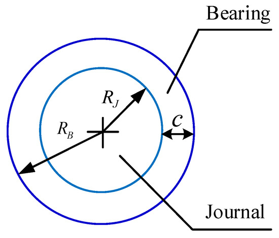
Figure 1.
Schematic of revolute joint with clearance.
2.2. Modeling of Mechanical System with Revolute Clearance Joint
It is necessary to incorporate a clearance model into the dynamics model of mechanical system with clearance joint. Figure 2 shows two bodies and connected by a revolute joint with clearance in free motion state and contact state, respectively. As shown in Figure 2a, represents the eccentric vector, which connects the centers of the bearing and the journal, and it is expressed as [43,44]
where and are described in coordinates reference frame, that is
where is the rotational transformation matrix and is the position vector of point Pk in respective body coordinate system . and are centers of mass of the connected bodies. and are body coordinate systems of bodies i and j, respectively.
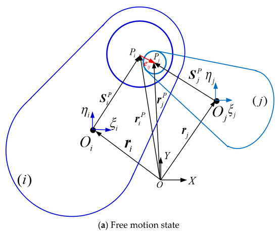
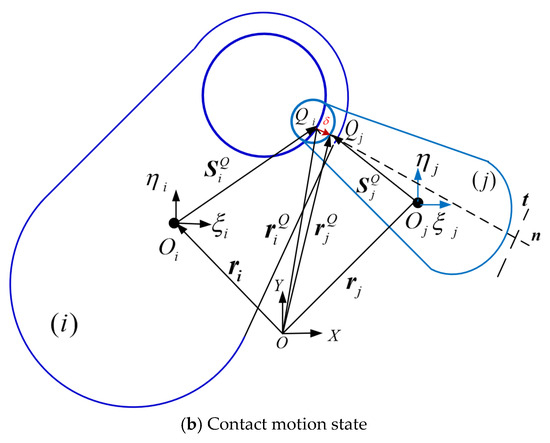
Figure 2.
Model of revolute joints with clearance in mechanical system.
Then, the magnitude of the eccentricity vector is expressed as . The unit vector is normal to the surfaces in impact between the bearing and the journal, and it aligns with the eccentricity vector. This unit vector can be written as
As shown in Figure 2b, the penetration depth caused by the impact between the journal and the bearing is calculated as:
where c is the size of radial clearance and is the magnitude of the eccentricity vector.
The candidate contact points on body and are and , respectively. The position of these points in the journal and bearing is expressed as
where the subscript and represent the bearing and the journal, respectively.
The components of the relative velocity of contact points in the normal and tangential plane of collision are represented by and , which are expressed as
where is the vector normal to , that is, rotating the vector in the counter clockwise direction by 90°.
2.3. Contact Force Model in Revolute Clearance Joint
Contact force model of revolute clearance joint should be carefully established to efficiently evaluate the contact forces in clearance joint. Therefore, many contact force models were proposed and suggested in the literature [29,45,46]. In this paper, the nonlinear continuous contact force model proposed by Lankarani and Nikravesh [45] is used to represent the normal contact in clearance joint, which is expressed as
where is the penetration depth, is the relative penetration velocity, and is initial relative velocity of the impact point. is the coefficient of restitution. n is the exponent and n = 1.5. is the contact stiffness coefficient and can be obtained by
The parameters and can be calculated by
where and represent Poisson’s ratio and Young’s modulus of the contact bodies, respectively.
The tangential contact of clearance joints is represented using friction force model. The best-known friction model is the Coulomb friction model, which is used to represent the friction behavior in impact and contact process. However, there are difficulties in numerical calculation when relative tangential velocity is close to zero. Here, in this paper, the clearance joint is considered as dry revolute clearance joint and a modified Coulomb friction model with dynamic friction coefficient is used for tangential contact of clearance joint, which can avoid numerical difficulties. The tangential friction force is evaluated as follows [43]:
where is the coefficient of dynamic friction for the tangential velocity and can be obtained by [43]:
where and are the static friction coefficient and dynamic friction coefficient, respectively, is the critical velocity of the maximum dynamic friction, and is the critical velocity of static friction.
The penetration depth can be used to determine whether the journal contacts with the bearing or not. The penetration depth is positive when the journal is in contact with the bearing, while it is negative during free motion state; that is, the journal is not in contact with the bearing. Therefore, the contact condition can be expressed as
3. Dynamics Equations of Dual-Manipulator System with Clearance Joint
3.1. Constraint Equation for Revolute Joint
In a simple way, a constraint is any condition that reduces the number of degrees of freedom in a mechanical system. The revolute joint is a bearing and journal type of joint that constrains the relative translation between the two bodies and , allowing only the relative rotations, as it is illustrated in Figure 3.
Figure 3.
Planar revolute joint connecting bodies i and j in mechanical system.
The kinematic conditions for the revolute joint require that two distinguished points, each one belonging to a different body, share the same position in space all the time. This means that the global position of a point in body is coincident with the global position of a point in body . Such condition is expressed by two algebraic equations that can be obtained from the following vector loop equation [44]:
which is re-written as
Thus, there is only one relative degree of freedom between two bodies that are connected by a planar revolute joint. For a constrained multibody mechanical system, the kinematic joints are described by a set of holonomic algebraic constraints and Φ can be written in a compact form as [47]
where is the vector of generalized coordinates and is the time variable.
3.2. Motion Equations of Dual-Manipulator System with Clearance
The dual-manipulator system on spacecraft is usually used to capture, assemble, and operate targets in space mission. The dual-manipulator system on spacecraft is as shown in Figure 4, which consists of two symmetrical manipulators installed on spacecraft body and each manipulator has two arms. In dynamic simulations, the spacecraft system is considered in a floating state and all the bodies are considered as rigid bodies. Gravity is ignored in dynamic simulations. The dual-manipulators are driven by the driving torques in each joint. The adjacent bodies are connected by revolute joints.
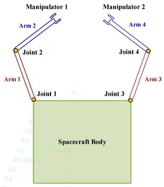
Figure 4.
Dual-manipulator system on spacecraft.
In this work, the dynamics model of the dual-manipulator system is established considering the clearance model. Clearance in joint leads to different motion states of bodies connected with the clearance joints: one is that the bodies move free in the clearance; the other is the bodies contact and impact. Thus, the dual-manipulator system with clearances is a variable topology system, which is solved by using dynamic segmentation modeling method. The equation of motion is obtained using the Lagrange multiplier method and expressed as
where is the generalized coordinate column matrix and is the generalized mass matrix. is the Jacobian matrix of constraint equation. is the generalized force matrix. is the Lagrange multiplier column matrix. The general generalized coordinates of each body are demonstrated , i = 1,2…5, which are spacecraft body, arm 1 and arm 2 of manipulator 1, as well as arm 3 and arm 4 of manipulator 2. In a multibody mechanical system, these generalized coordinates are related by constraint equations , as shown in Equation (14), where the constraints result from the kinematic constraint of each revolute joint, which are joint 1 to joint 4. It should be noted that the kinematic constraint of clearance joint is replaced by contact force. Here, in Equation (17) represents the contact force, which includes both normal contact force and tangential friction force, and it can be expressed as
4. Dynamics Simulation Results and Discussion
4.1. Structure and Properties of the Dual-Manipulator System on Spacecraft
In this section, an application example is presented to investigate the effects of clearances on motion accuracy and dynamic performance of the dual-manipulator system. The mass and inertia properties of the dual-manipulator system on spacecraft are presented in Table 1. The centers of mass of each arm are at the geometric centers of each link. Table 2 lists the parameters used in the dynamic simulations for the dual-manipulator system. The initial positions of arm 1 and arm 2 are -π/4 and π/2, respectively. The initial positions of arm 3 and arm 4 are π/4 and π/2, respectively. The initial velocity of each arm is zero.

Table 1.
Geometry, mass, and inertia properties of dual-manipulator system.
Table 2.
Parameters used in dynamic simulation of robot manipulators on spacecraft.
In order to study the effects of clearance on dynamic performances and motion accuracy of the dual-manipulator system, different case studies are performed and discussed, which is shown in Table 3.
Table 3.
Case studies in the dynamic simulations.
4.2. Effects of Clearance on Dynamic Responses of Dual-Manipulator System
In this section, dynamic simulations for dual-robot manipulator system on spacecraft are performed. The dynamic simulation results obtained from actual dual-manipulator system with clearances are compared with that of ideal dual-manipulator system without clearances.
4.2.1. Results and Discussions of Case 1 and Case 2
In this subsection, we consider that clearance exists in one manipulator; that is, one of the revolute joints in manipulator 1 is considered as imperfect with clearance. Consequently, two case studies are performed. In the first case study (case 1), it is assumed that the revolute joint 2 between arm 1 and arm 2 of manipulator 1 is imperfect joint with clearance, while the other joints, which are revolute joint 1, revolute joint 3, and revolute joint 4, are ideal joints without clearances. Clearance size of the imperfect joint 2 is considered as 0.5 mm in the dynamic simulation. In the second case study (case 2), it is assumed that the revolute joint 1 between arm 1 and spacecraft body is imperfect joint with clearance, while the other joints, which are revolute joint 2, revolute joint 3, and revolute joint 4, are ideal joints without clearances. Clearance size of the imperfect joint 1 is considered as 0.5 mm in the dynamic simulation.
The simulation results of first case study are presented as Figure 5, Figure 6, Figure 7, Figure 8, Figure 9 and Figure 10. Figure 5 presents the angular displacements of each arm for the dual-manipulator system with clearance and the ideal dual-manipulator system without clearances. Figure 6 presents the angular motion errors of each arm of dual-manipulator when considering clearance in joint 2. It should be noted that the motion errors are calculated as the differences between the simulation results of imperfect dual-manipulator system with clearance and ideal dual-manipulator without clearance.
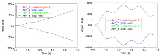
Figure 5.
Angle of each arm of the dual-manipulator system considering clearance in joint 2 (case 1).
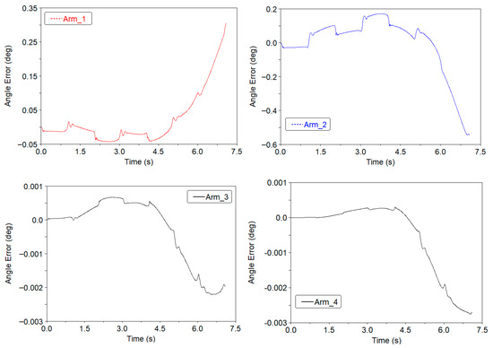
Figure 6.
Angle error of each arm considering clearance in joint 2 (case 1).
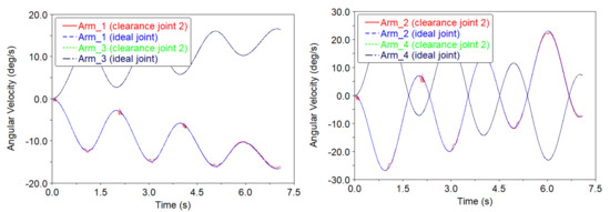
Figure 7.
Angular velocity of each arm of the dual-manipulator system considering clearance in joint 2 (case 1).
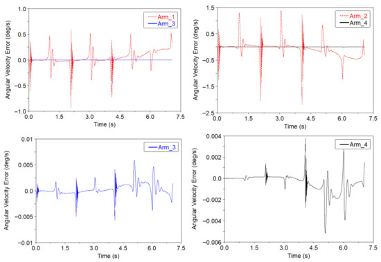
Figure 8.
Angular velocity error of each arm considering clearance in joint 2 (case 1).
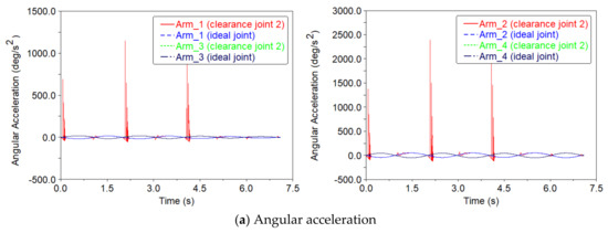
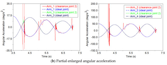
Figure 9.
Angular acceleration of each arm of the dual-manipulator system considering clearance joint 2 (case 1).
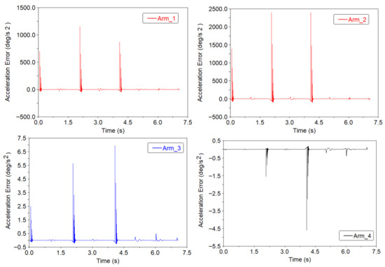
Figure 10.
Angular acceleration error of each arm considering clearance in joint 2 (case 1).
Figure 5 shows that the angular displacements of arm 1 and arm 3 obtained from ideal dual-manipulator are approximate with that from imperfect manipulator with clearance. However, the angular displacements of arm 2 are obviously affected by the clearance, which is represented by motion deviation from that of the ideal case without clearance. Consequently, Figure 6 clearly shows that clearance leads to obvious motion errors of each arm and the motion errors of arm 1 and arm 2 of manipulator 1 are larger than the motion errors of arm 3 and arm 4 of manipulator 2 for the dual-manipulator system. The maximum absolute values of angle error are 0.3037°, 0.5459°, 0.0022°, and 0.0028° for arm 1, arm 2, arm 3, and arm 4, respectively. It is because the revolute joint 2 between arm 1 and arm 2 of manipulator 1 is considered as imperfect joint with clearance, while the joints in manipulator 2 are considered as ideal joints in case 1. Due to clearance results in large contact and impact forces in clearance joint 2 of manipulator 1, the contact and impact forces also affect the motion of arm 3 and arm 4 of manipulator 2. Therefore, clearance in manipulator 1 also leads to motion errors of manipulator 2. It indicates that clearance leads to a decrease in the motion accuracy of the dual-manipulator system.
Figure 7 presents the angular velocity of arm 1 and arm 2 of manipulator 1 as well as arm 3 and arm 4 of manipulator 2 for case 1, where clearance exists in joint 2. Figure 8 presents the velocity errors of each arm. Figure 7 shows that the angular velocities of arm 1 and arm 2 of manipulator 1 oscillate with higher peaks. Also, the angular velocities of arm 3 and arm 4 have less oscillation. Figure 8 shows clearance leads to obvious angular velocity errors of each arm. The motion velocity errors of arm 1 and arm 2 of manipulator 1 are much larger than the motion velocity errors of arm 3 and arm 4 of manipulator 2 for the dual-manipulator system. The maximum absolute values of angular velocity error are 0.9299°/s, 2.1781°/s, 0.0059°/s, and 0.0052°/s for arm 1, arm 2, arm 3, and arm 4, respectively. Therefore, clearance has an obvious influence on the motion velocity of manipulator 1. The reason is that clearance exists in joint 2 between arm 1 and arm 2 of manipulator 1. In addition, due to the spacecraft system being in a floating state, the clearance in manipulator 1 also affects the responses of manipulator 2.
Figure 9 presents the angular acceleration of arm 1 and arm 2 of manipulator 1 as well as arm 3 and arm 4 of manipulator 2 for the dual-manipulator system. Figure 10 presents the angular acceleration errors of each arm when considering clearance. Figure 9 shows that the motion acceleration of manipulator 1 is extreme oscillation around that of the ideal manipulator 1. The accelerations represent very large peaks, which are due to the contact and impact forces resulting from clearance joint. Figure 10 shows clearance leads to obvious angular acceleration errors of each arm. The motion acceleration errors of arm 1 and arm 2 of manipulator 1 are much larger than the motion velocity errors of arm 3 and arm 4 of manipulator 2, which is due to clearance existing in joint 2 between arm 1 and arm 2. The maximum absolute values of angular acceleration error are 868.7952°/s2, 2395.9363°/s2, 6.9255°/s2, and 4.5921°/s2 for arm 1, arm 2, arm 3, and arm 4, respectively. Therefore, when considering clearance, the motion acceleration is an obvious oscillation with extreme higher peaks, which leads to the decrease in dynamic performance as well as motion stability of the dual-manipulator system.
The resulting peaks in angular velocities and accelerations result from the contact and impact forces in clearance joint. The contact forces in joint 2 with clearance and ideal joint without clearance for case 1 are presented in Figure 11. It can be found that the existence of clearance leads to contact and impact forces and the contact forces oscillate with very high peaks. Also, the contact forces are increased from the ideal joint. The maximum absolute values of contact and impact forces in clearance joint are 8.7432 N and 4.8132 N in x and y directions, respectively. On the contrary, the maximum absolute values of reaction forces in ideal joint are 0.7012 N and 0.2579 N in x and y directions, respectively. Therefore, it indicates that the existence of clearance leads to contact and impact forces and affects the movement accuracy and stability of dual-manipulator.
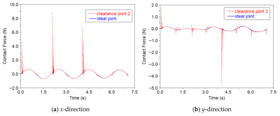
Figure 11.
Contact forces in clearance joint 2 (case 1).
The simulation results of the second case study are presented in Figure 12, Figure 13, Figure 14, Figure 15 and Figure 16. Comparing with Figure 5, Figure 6, Figure 7, Figure 8, Figure 9 and Figure 10 obtained from dynamic simulation of case 1, the similar phenomenon can be found from Figure 12, Figure 13, Figure 14, Figure 15 and Figure 16 obtained from case 2. Figure 12 also shows that clearance leads to obvious motion errors of each arm and the motion errors of arm 1 and arm 2 of manipulator are larger than the motion errors of arm 3 and arm 4 of manipulator 2 for the dual-manipulator system. This is due to clearance existing in joint 1 between arm 1 and spacecraft body. The maximum absolute values of angle error are 0.5325°, 0.7947°, 0.0111°, and 0.0105° for arm 1, arm 2, arm 3, and arm 4, respectively. Additionally, comparing the motion angle errors between Figure 6 and Figure 13, it can be found that the motion angle errors of each arm are increased. It indicates that the clearance that exists in joint 1 presents more obvious effects than clearance that exists in joint 2.
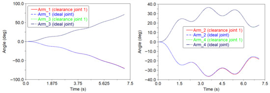
Figure 12.
Angle of each arm of the dual-manipulator system considering clearance in joint 1 (case 2).
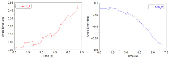
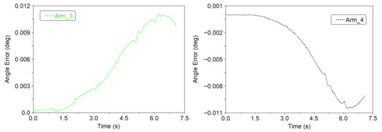
Figure 13.
Angle error of each arm considering clearance in joint 1 (case 2).
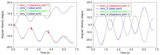
Figure 14.
Angular velocity of each arm considering clearance in joint 1 (case 2).
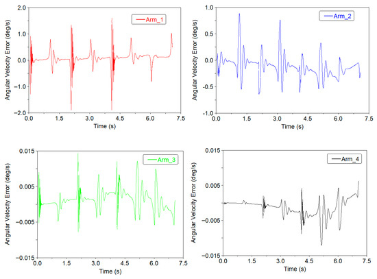
Figure 15.
Angular velocity error of each arm considering clearance in joint 1 (case 2).
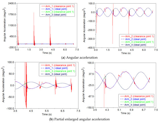
Figure 16.
Angular acceleration of each arm considering clearance in joint 1 (case 2).
Figure 14 shows that the angular velocities of arm 1 and arm 2 of manipulator 1 oscillate with higher peaks. Also, the angular velocities of arm 3 and arm 4 of manipulator have less oscillation. Figure 15 shows clearance leads to obvious angular velocity errors of each arm. The motion velocity errors of arm 1 and arm 2 of manipulator 1 are much larger than the motion velocity errors of arm 3 and arm 4 of manipulator 2 for the dual-manipulator system. The maximum absolute values of velocity error are 1.9013°/s, 0.8826°/s, 0.0144°/s, and 0.0121°/s for arm 1, arm 2, arm 3, and arm 4, respectively. Therefore, clearance has an obvious influence on the motion velocity of manipulator 1, which is because clearance exists in joint 1 of manipulator 1. Comparing Figure 15 with Figure 8, the angular velocity errors of arm 1, arm 3, and arm 4 are increasingly obvious, but the angular velocity errors of arm 2 decrease. The reason is that clearance exists in joint 1 between arm 1 and spacecraft body. Therefore, it can be found that the location of clearance joint displays different effects on the dynamic responses and motion errors.
Figure 16 shows that the motion acceleration of manipulator 1 is extreme oscillation around that of the ideal manipulator 1. The accelerations represent very large peaks, which is due to the contact and impact forces resulting from clearance joint 1. Figure 17 shows clearance leads to obvious angular acceleration errors of each arm. Also, the motion acceleration errors of arm 1 and arm 2 of manipulator 1 are much larger than the motion velocity errors of arm 3 and arm 4 of manipulator 2. The maximum absolute values of angular acceleration error are 2016.3226°/s2, 343.2609°/s2, 12.7258°/s2, and 7.4723°/s2 for arm 1, arm 2, arm 3, and arm 4, respectively. Comparing the acceleration responses and errors obtained from case 1, it shows that the motion acceleration of arm 1, arm 3, and arm 4 obtained from case 2 has much more obvious oscillation with higher peaks. This is because clearance exists in joint 1 between arm 1 and spacecraft body.
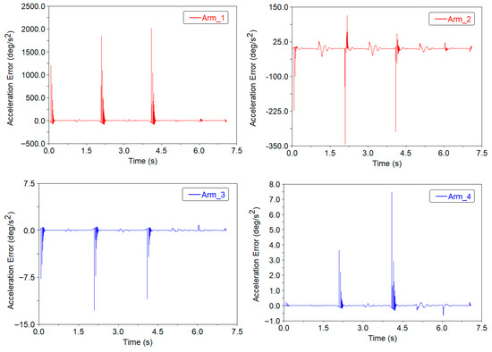
Figure 17.
Angular acceleration error of each arm considering clearance in joint 1 (case 2).
The contact forces in clearance joint for case 2 and ideal case without clearance are presented in Figure 18. It can be found that the existence of clearance leads to contact and impact forces and the contact forces oscillate with very high peaks. Also, the contact force is increased from the ideal joint. The maximum absolute values of contact and impact forces in clearance joint are 10.7556 N and 5.4648 N in x and y directions, respectively. On the contrary, the maximum absolute values of reaction forces in ideal joint are 0.8417 N and 0.3092 N in x and y directions, respectively. Comparing the contact forces obtained from case 1, it shows that the contact forces are increased. It indicates that the existence of clearance in joint 1 induces higher contact forces.
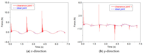
Figure 18.
Contact forces in clearance joint 1 (case 2).
In addition, the numerical results obtained in this work are compared to other studies from previous studies on clearance effects [13,14,23,31,43,44], which also showed that clearances had important effects on the dynamic responses, especially affecting the acceleration of multibody mechanical systems.
4.2.2. Results and Discussions of Case 3
Further, in the third case study (case 3), clearances exist in both the two manipulators of the dual-manipulator system. Here, we consider that each manipulator has one clearance joint. Thus, in such cases, the revolute joint 2 between arm 1 and arm 2 in manipulator 1 as well the revolute joint 4 between arm 3 and arm 4 in manipulator 2 are considered as imperfect joints with clearances. Clearance size in each imperfect joint is 0.5 mm in the dynamic simulations. The simulation results obtained from dual-manipulator system with clearances are also compared with that of ideal dual-manipulator system without clearance joints.
Figure 19 presents the angular displacements of each arm of the dual-manipulator system with clearances. Figure 20 presents the angular motion errors of each arm when considering clearances. Figure 19 shows that the angular displacements of arm 2 and arm 4 of the dual-manipulator are obviously affected by the clearances. Figure 20 clearly shows that clearances lead to obvious motion errors of each arm. Also, the motion errors of arm 2 are larger than the motion errors of arm 1 of manipulator 1. Similarly, the motion errors of arm 4 are larger than the motion errors of arm 3 of manipulator 2. The maximum absolute values of angle error are 0.3025°, 0.5417°, 0.3025°, and 0.5417° for arm 1, arm 2, arm 3, and arm 4, respectively. It should be noted that the maximum absolute values of angle errors are the same for manipulator 1 and manipulator 2, which is due to the manipulator arms being symmetrically installed and synchronous motion. Also, the clearance joints have the same clearance size and position in this case study. Compared with Figure 6, the motion errors of arm 3 and arm 4 for manipulator are increasingly obvious. It is because clearances exist in both the two manipulators; that is, joint 2 and joint 4 are considered as imperfect joints with clearances in case 3. Therefore, it indicates that the more clearances considered in the dual-manipulator system, the larger the decrease in the motion precision of the dual-manipulator system that is caused.
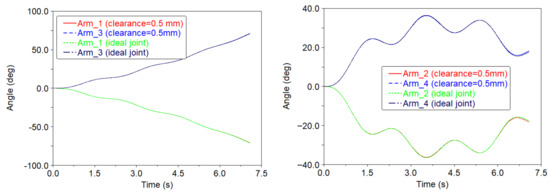
Figure 19.
Angle of each arm of the dual-manipulator system considering clearances in joints 2 and 4 (case 3).
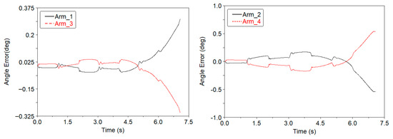
Figure 20.
Angle error of each arm considering clearances in joints 2 and 4 (case 3).
Figure 21 presents the angular velocities of each arm of the dual-manipulator system with clearances. Figure 22 presents the angular velocity errors of each arm when considering clearances. From Figure 21, it can be found that the angular velocities of each arm oscillate around the angular velocity obtained from the ideal case. The angular velocities present higher peaks. Figure 22 shows clearances lead to obvious angular velocity errors of each manipulator and all arms present large velocity errors. The maximum absolute values of velocity error are 0.9243°/s, 2.1806°/s, 0.9243°/s, and 2.1806°/s for arm 1, arm 2, arm 3, and arm 4, respectively. Comparing Figure 7 and Figure 8, the angular velocities of all arms oscillate. The motion velocity errors of arm 2 and arm 4 are larger than the motion velocity errors of arm 1 and arm 3 for the dual-manipulator system. Also, the motion velocity errors of arm 3 and arm 4 of the manipulator 2 increase significantly. This is because joint 4 between arm 3 and arm 4 is also considered as imperfect joint with clearance.
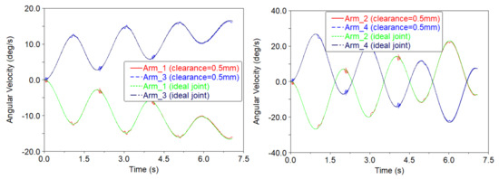
Figure 21.
Angular velocity of each arm considering clearances in joints 2 and 4 (case 3).
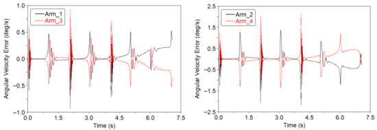
Figure 22.
Angular velocity error of each arm considering clearances in joints 2 and 4 (case 3).
Figure 23 presents the angular acceleration of each arm of the dual-manipulator system with clearances in both the two manipulators. Figure 24 presents the angular acceleration errors of each arm when considering clearances. From Figure 23, it can be found that the angular accelerations of each arm are extreme oscillations with very large peaks. Figure 24 shows clearances lead to very large angular acceleration errors of each arm. The maximum absolute values of angular acceleration error are 1150.9377°/s2, 2411.6975°/s2, 1150.9377°/s2, and 2411.6975°/s2 for arm 1, arm 2, arm 3, and arm 4, respectively. Comparing Figure 9 and Figure 10, the acceleration oscillations of arms 3 and 4 are obviously increased with very large peaks, which cause the motion acceleration errors of arm 3 and arm 4 of the manipulator 2 to also increase significantly. Additionally, acceleration errors of arm 2 and arm 4 are larger than the motion acceleration errors of arm 1 and arm 3 of the dual-manipulator system.
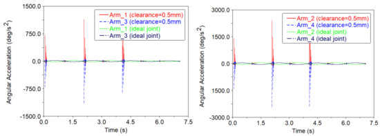
Figure 23.
Angular acceleration of each arm considering clearances in joints 2 and 4 (case 3).
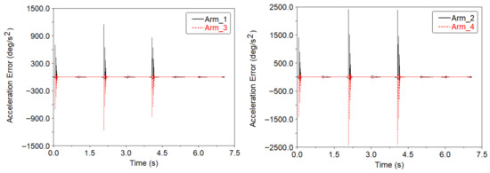
Figure 24.
Angular acceleration error of each arm considering clearances in joints 2 and 4 (case 3).
The contact forces in clearance joint 2 and joint 3 for case 3 and ideal case without clearances are presented in Figure 25 and Figure 26. It also can be found that the contact forces oscillate with very high peaks. The maximum absolute values of contact and impact force in clearance joint 2 are 8.7943 N and 4.8210 N in x and y directions, respectively. On the contrary, the maximum absolute values of reaction forces in ideal joint 2 are 0.7012 N and 0.2579 N in x and y directions, respectively. Due to the manipulator arms being symmetrically installed and that the clearance joints have the same clearance size and position, the maximum absolute values of contact and impact force in clearance joint 4 are 8.7943 N and 4.8210 N in x and y directions, respectively. Also, the maximum absolute values of reaction forces in ideal joint 4 are 0.7012 N and 0.2579 N in x and y directions, respectively.
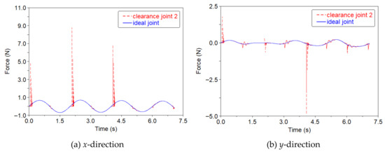
Figure 25.
Contact forces in clearance joint 2 (case 3).
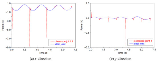
Figure 26.
Contact forces in clearance joint 4 (case 3).
4.2.3. Results and Discussions of Case 4 and Case 5
Clearance size is one of the most important factors affecting the dynamic responses of dual-manipulator system. Further, in this subsection, the effects of clearance size on the dynamic responses and motion errors of the dual-manipulator system are investigated. In the dynamic simulations, revolute joint 2 between arm 1 and arm 2 in manipulator 1 as well the revolute joint 4 between arm 3 and arm 4 in manipulator 2 are considered as imperfect joints with clearances. Consequently, the dynamic simulations of the dual-manipulator system are performed considering clearance size is 0.25 mm and 1 mm in each imperfect joint for case 4 and case 5, respectively.
Figure 27 and Figure 28 present the angular acceleration of each arm of the dual-manipulator system, where clearance size is 0.25 mm and 1 mm, respectively. Comparing Figure 23, Figure 27 and Figure 28, it can be found that as clearance size increases, the dynamic responses of the dual-manipulator display more obvious oscillations and much higher oscillation peaks. Therefore, bigger size of clearance will significantly increase the oscillations peaks of the dual-manipulator. Additionally, Figure 20, Figure 29 and Figure 30, and clearly present that the bigger size of clearance will lead to larger motion errors. The maximum absolute values of angle error are 0.2922°/s, 0.5292°/s, 0.2922°/s, and 0.5292°/s for arm 1, arm 2, arm 3, and arm 4 of case 4, respectively. The maximum absolute values of angle error are 0.3198°/s, 0.6286°/s, 0.3198°/s, and 0.6286°/s for arm 1, arm 2, arm 3, and arm 4 of case 5, respectively. Thus, the simulation results for different clearance sizes indicate that a bigger size of clearance will cause the dynamic performance of dual-manipulator system to be much worse and the motion stability and accuracy of the dual-manipulator to be reduced.
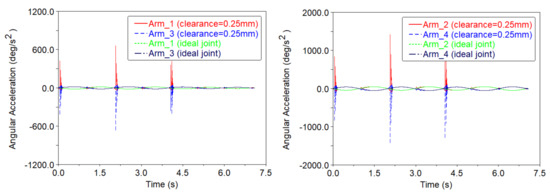
Figure 27.
Angular acceleration of each arm considering clearance size is 0.25 mm (case 4).
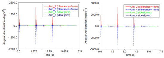
Figure 28.
Angular acceleration of each arm considering clearance size is 1 mm (case 5).
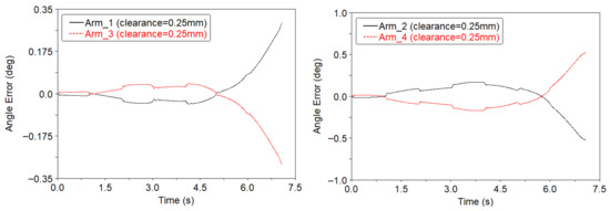
Figure 29.
Angle errors of each arm considering clearance size is 0.25 mm (case 4).
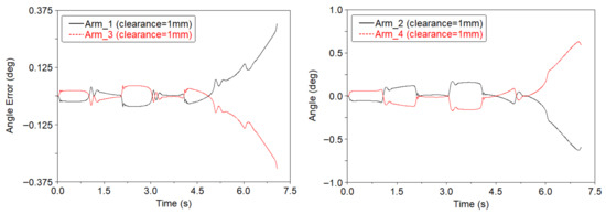
Figure 30.
Angle errors of each arm considering clearance size is 1 mm (case 5).
It should be noted that the maximum absolute peak values of motion errors are the same for manipulator 1 and manipulator 2 in case 3, case 4, and case 5, respectively, which is due to the manipulator arms being symmetrically installed and having synchronous motion. Also, the clearance joints have the same clearance size and position in each case study.
Additionally, the numerical results of clearance size obtained in this work are compared to other published studies [31,42,43,44], which also showed that bigger size of clearance causes higher oscillation peaks of the mechanical system. Therefore, the investigation results in this work are validated by other published works on the field of dynamics of mechanical systems with clearances.
5. Conclusions
In this paper, the dynamic responses and motion accuracy of dual-manipulator system on spacecraft considering clearance effect are investigated numerically. The effects of clearances are analyzed via different case studies qualitatively and quantitatively. The imperfect joint with clearance is considered as contact force constraints containing normal contact force and tangential friction force. A dual-manipulator system on a spacecraft is used as the numerical example to perform the investigation. Some findings of the presented work are as follows.
(1) The motion accuracy and stability of the dual-manipulator system are obviously reduced when considering clearances. The motion displacements of the dual-manipulator considering clearance deviate from the ideal dual-manipulator without clearances. The angular velocities of dual-manipulator are obvious oscillations around the angular velocity of the ideal dual-manipulator. The angular acceleration of dual-manipulator with clearances has obvious oscillations and the peaks are significantly increased. The resulting peaks in angular velocities and accelerations result from the contact and impact forces in clearance joints. The contact forces increase due to joint clearances and can increase more than 10 times in some cases. Therefore, the angular velocity and angular acceleration are sensitive to the clearance effect
(2) Different locations of clearance joint show different effects on the dynamic responses of the dual-manipulator system on spacecraft. Clearance existing in joint 1 between the arm and spacecraft body presents more obvious effects than clearance existing in joint 2 between arms. The maximum absolute values of angle error of each arm are 0.3037°, 0.5459°, 0.0022°, and 0.0028° for case 1, and 0.5325°, 0.7947°, 0.0111°, and 0.0105° for case 2.
(3) More clearances are considered in the dual-manipulator system; the motion accuracy and stability of the dual-manipulator system are much lower. Moreover, bigger size of clearance induces larger oscillation peaks of angular velocities and accelerations, which further causes the dynamics performance of dual-manipulator system to be much worse. The maximum absolute values of angle error of each arm are 0.3025°, 0.5417°, 0.3025°, and 0.5417° for case 3; 0.2922°/s, 0.5292°/s, 0.2922°/s, and 0.5292°/s for case 4; and 0.3198°/s, 0.6286°/s, 0.3198°/s, and 0.6286°/s for case 5.
(4) The precise operation tasks of dual-manipulator require higher precision and reliability. However, the motion accuracy and stability of the dual-manipulator system are obviously reduced due to clearances. The contact forces in clearance joints also increase significantly. Further, clearance effects even lead to the failure of working tasks of the dual-manipulator system. This work provides an effective method to investigate the dynamics responses of dual-manipulator system on spacecraft with clearances and improves the practical engineering applications. In this paper, the revolute clearance joint is considered as planar joint with dry friction. In the future, spatial revolute clearance joint, lubrication in clearance joint, and experimental test of manipulators also need to be further studied.
Author Contributions
Conceptualization, Z.B.; methodology, Y.K. and Z.B.; software, Y.K., Z.B. and C.W.; validation, C.W.; formal analysis, Y.K. and Z.B.; investigation, Y.K. and Z.B.; data curation, Y.K. and Z.B.; writing—original draft preparation, Y.K.; writing—review and editing, Z.B.; visualization, Z.B.; supervision, C.W.; project administration, Z.B.; All authors have read and agreed to the published version of the manuscript.
Funding
This work is supported by the Natural Science Foundation of Shandong Province (ZR2023ME171).
Data Availability Statement
All the data used in this investigation are presented in the paper.
Conflicts of Interest
The authors declare no conflicts of interest.
References
- Flores-Abad, A.; Ma, O.; Pham, K.; Ulrich, S. A review of space robotics technologies for on-orbit servicing. Prog. Aerosp. Sci. 2014, 68, 1–26. [Google Scholar] [CrossRef]
- Garcia-Luna, F.; Rodriguez-Ramirez, A.; Nandayapa, M.; Flores-Abad, A. Augmented Reality-Based Robotic System for In-Space Servicing. IEEE Aerosp. Electron. Syst. Mag. 2024, 39, 18–31. [Google Scholar] [CrossRef]
- Liu, D.; Chen, L. Dual-Arm Space Robot On-Orbit Operation of Auxiliary Docking Prescribed Performance Impedance Control. Aerospace 2024, 11, 867. [Google Scholar] [CrossRef]
- Subudhi, B.; Morris, A.S. Dynamic modelling; simulation and control of a manipulator with flexible links and joints. Robot. Auton. Syst. 2002, 41, 257–270. [Google Scholar] [CrossRef]
- Wei, C.; Liu, T.X.; Zhao, Y. Grasping Strategy in Space Robot Capturing Floating Target. Chin. J. Aeronaut. 2010, 23, 591–598. [Google Scholar] [CrossRef]
- Martins, J.M.; Mohamed, Z.; Tokhi, M.O.; Sa da Costa, J.; Botto, M.A. Approaches for Dynamic Modeling of Flexible Manipulator Systems. IEE Proc.-Control. Theory Appl. 2003, 150, 401–411. [Google Scholar] [CrossRef]
- Xu, B.; Fujimoto, K.; Hayakawa, Y. Control of two-link flexible manipulators via generalized canonical transformation. In Proceedings of the 2004 IEEE Conference on Robots, Automation and Mechatronics, Singapore, 1–3 December 2004; pp. 107–112. [Google Scholar]
- Park, C.; Ramirez-Serrano, A.; Bisheban, M. Adaptive incremental nonlinear dynamic inversion control for aerial manipulators. Aerospace 2024, 11, 671. [Google Scholar] [CrossRef]
- Azizkhani, M.; Godage, I.S.; Chen, Y. Dynamic control of soft robotic arm: A simulation study. IEEE Robot. Autom. Lett. 2022, 7, 3584–3591. [Google Scholar] [CrossRef]
- Shabana, A.A.; Bai, Z.F. Actuation and Motion Control of Flexible Robots: Small Deformation Problem. ASME J. Mech. Robot. 2022, 14, 011002. [Google Scholar] [CrossRef]
- Jia, S.; Shan, J. Finite-time trajectory tracking control of space manipulator under actuator saturation. IEEE Trans. Ind. Electron. 2019, 67, 2086–2096. [Google Scholar] [CrossRef]
- Cornejo, J.; Weitzendel, A.; Baca, J.; Cena, C.E.G. Aerospace Bionic Robotics: BEAM-D Technical Standard of Biomimetic Engineering Design Methodology Applied to Mechatronics Systems. Biomimetics 2025, 10, 668. [Google Scholar] [CrossRef]
- Varedi, S.M.; Daniali, H.M.; Dardel, M. Dynamic synthesis of a planar slider-crank mechanism with clearances. Nonlinear Dyn. 2015, 79, 1587–1600. [Google Scholar] [CrossRef]
- Wang, X.; Liu, G.; Ma, S.; Tong, R. Study on dynamic responses of planar multibody systems with dry revolute clearance joint: Numerical and experimental approaches. J. Sound Vib. 2019, 438, 116–138. [Google Scholar] [CrossRef]
- Tan, H.; Hu, Y.; Li, L. Effect of friction on the dynamic analysis of slider-crank mechanism with clearance joint. Int. J. Mech. Sci. 2019, 115, 20–40. [Google Scholar] [CrossRef]
- Zhao, Q.; Guo, J.; Hong, J.; Liu, Z. Analysis of angular errors of the planar multi-closed-loop deployable mechanism with link deviations and revolute joint clearances. Aerosp. Sci. Tech. 2019, 87, 25–36. [Google Scholar] [CrossRef]
- Daniel, G.B.; Cavalca, K.L. Analysis of the dynamics of a slider-crank mechanism with hydrodynamic lubrication in the connecting rod-slider joint clearance. Mech. Mach. Theory 2011, 46, 1434–1452. [Google Scholar] [CrossRef]
- Zhao, B.; Dai, X.D.; Zhang, Z.N. Numerical study of parametric effects on joint wear in the flexible multibody systems with different flexibilities and clearance sizes. Proc. Inst. Mech. Eng. Part J J. Eng. Tribol. 2014, 228, 819–835. [Google Scholar] [CrossRef]
- Olyaei, A.A.; Ghazavi, M.R. Stabilizing slider-crank mechanism with clearance joints. Mech. Mach. Theory 2012, 53, 17–29. [Google Scholar] [CrossRef]
- Li, J.; Huang, H.; Yan, S.; Yang, Y. Kinematic accuracy and dynamic performance of a simple planar space deployable mechanism with joint clearance considering parameter uncertainty. Acta Astronaut. 2017, 136, 34–45. [Google Scholar] [CrossRef]
- Brogliato, B. Feedback control of multibody systems with joint clearance and dynamic backlash, a tutorial. Multibody Syst. Dyn. 2018, 42, 283–315. [Google Scholar] [CrossRef]
- Li, Y.; Wang, Z.; Wang, C.; Huang, W. Effects of torque spring, CCL and latch mechanism on dynamic response of planar solar arrays with multiple clearance joints. Acta Astronaut. 2017, 132, 243–255. [Google Scholar] [CrossRef]
- Jiang, S.; Zhao, M.; Liu, J.; Lin, Y.; Xiao, L.; Jia, Y. Dynamic response and nonlinear characteristics of multi-link mechanism with clearance joints. Arch. Appl. Mech. 2023, 93, 3461–3493. [Google Scholar] [CrossRef]
- Erkaya, S.; Uzmay, I. Determining link parameters using genetic algorithm in mechanisms with joint clearance. Mech. Mach. Theory 2009, 44, 222–234. [Google Scholar] [CrossRef]
- Zhang, X.; Zhang, X. Minimizing the influence of revolute joint clearance using the planar redundantly actuated mechanism. Robot. Comput.-Integr. Manuf. 2017, 46, 104–113. [Google Scholar] [CrossRef]
- Li, Y.; Wang, C.; Huang, W. Dynamics analysis of planar rigid-flexible coupling deployable solar array system with multiple revolute clearance joints. Mech. Syst. Signal Process. 2019, 117, 187–209. [Google Scholar] [CrossRef]
- Amiri, A.; Dardel, M.; Daniali, H.M. Effects of passive vibration absorbers on the mechanisms having clearance joints. Multibody Syst. Dyn. 2019, 47, 363–395. [Google Scholar] [CrossRef]
- Zhan, Z.; Zhang, X.; Zhang, H.; Chen, G. Unified motion reliability analysis and comparison study of planar parallel manipulators with interval joint clearance variables. Mech. Mach. Theory 2019, 138, 58–75. [Google Scholar] [CrossRef]
- Tian, Q.; Flores, P.; Lankarani, H.M. A comprehensive survey of the analytical, numerical and experimental methodologies for dynamics of multibody mechanical systems with clearance or imperfect joints. Mech. Mach. Theory 2018, 122, 1–57. [Google Scholar] [CrossRef]
- Tsai, M.J.; Lai, T.H. Kinematic sensitivity analysis of linkage with joint clearance based on transmission quality. Mech. Mach. Theory 2004, 39, 1189–1206. [Google Scholar] [CrossRef]
- Flores, P.; Ambrósio, J.; Claro, J.C.P.; Lankarani, H.M. Dynamic behaviour of planar rigid multi-body systems including revolute joints with clearance. Proc. Inst. Mech. Eng. Part K J. Multi Body Dyn. 2007, 221, 161–174. [Google Scholar] [CrossRef]
- Dong, X.; Sun, Y.; Wu, X.; Wang, R. Dynamic modeling and performance analysis of toggle-linkage presses considering mixed clearances and flexibility. Int. J. Non-Linear Mech. 2022, 147, 104243. [Google Scholar] [CrossRef]
- Chen, X.; Pan, P.; Wang, T. Nonlinear dynamic characteristics analysis of planar mechanism multibody system considering lubrication clearances. Int. J. Precis. Eng. Manuf. 2023, 24, 2033–2055. [Google Scholar] [CrossRef]
- Gao, S.; Wang, L.; Zhang, Y. Modeling and dynamic characteristic analysis of high-speed angular contact ball bearing with variable clearance. Tribol. Int. 2023, 182, 108330. [Google Scholar] [CrossRef]
- Chen, Y.; Wu, X.; Wu, K.; Sun, Y.; Yu, C.; Xia, X. An experimental and analytical study on dynamic behaviors of high-precision mechanism including revolute clearance joints. J. Braz. Soc. Mech. Sci. 2022, 44, 120. [Google Scholar] [CrossRef]
- Bai, Z.F.; Xu, F.; Zhao, J.J. Numerical and experimental study on dynamics of the planar mechanical system considering two revolute clearance joints. Int. J. Mech. Sys. Dyn. 2021, 1, 256–266. [Google Scholar] [CrossRef]
- Bai, Z.F.; Jiang, X.; Li, J.Y.; Zhao, J.J.; Zhao, Y. Dynamic Analysis of Mechanical System Considering Radial and Axial Clearances in 3D Revolute Clearance Joints. J. Vib. Control. 2021, 27, 1893–1909. [Google Scholar] [CrossRef]
- Chen, X.; Yang, W. Dynamic Modeling and Analysis of Spatial Parallel Mechanism with Revolute Joints Considering Radial and Axial Clearances. Nonlinear Dyn. 2021, 106, 1929–1953. [Google Scholar] [CrossRef]
- Li, S.; Zheng, Y.; Wu, H.; Zhang, J.; Ohsaki, M.; Yang, C.; Luo, Y. Dynamics Analysis of Deployment Process of the Bennett Linkage with Revolute Clearance Joints. Nonlinear Dyn. 2024, 112, 10911–10935. [Google Scholar] [CrossRef]
- Wu, W.; Xiang, S. Dynamic analysis of space robot manipulator considering clearance joint and parameter uncertainty: Modeling, analysis and quantification. Acta Astronaut. 2020, 169, 158–169. [Google Scholar] [CrossRef]
- Meng, D.; She, Y.; Xu, W.; Lu, W.; Liang, B. Dynamic modeling and vibration characteristics analysis of flexible-link and flexible-joint space manipulator. Multibody Syst. Dyn. 2018, 43, 321–347. [Google Scholar] [CrossRef]
- Miao, H.; Li, B.; Liu, J.; He, A.; Zhu, S. Effects of revolute clearance joint on the dynamic behavior of a planar space arm system. Proc. Inst. Mech. Eng. Part G J. Aerosp. Eng. 2019, 233, 1629–1644. [Google Scholar] [CrossRef]
- Bai, Z.F.; Zhao, J.J.; Chen, J.; Zhao, Y. Design optimization of dual-axis driving mechanism for satellite antenna with two planar revolute clearance joints. Acta Astronaut. 2018, 144, 80–89. [Google Scholar] [CrossRef]
- Bai, Z.F.; Liu, Y.Q.; Sun, Y. Investigation on dynamic responses of dual-axis positioning mechanism for satellite antenna considering joint clearance. J. Mech. Sci. Technol. 2015, 29, 453–460. [Google Scholar] [CrossRef]
- Lankarani, H.M.; Nikravesh, P.E. A Contact Force Model with Hysteresis Damping for Impact Analysis of Multibody Systems. J. Mech. Des. 1990, 112, 369–376. [Google Scholar] [CrossRef]
- Bai, Z.F.; Zhao, Y. Dynamic behavior analysis of planar mechanical systems with clearance in revolute joints using a new hybrid contact force model. Int. J. Mech. Sci. 2012, 54, 190–205. [Google Scholar] [CrossRef]
- Nikravesh, P.E. Computer-Aided Analysis of Mechanical Systems; Prentice-Hall: Englewood Cliffs, NJ, USA, 1988. [Google Scholar]


Disclaimer/Publisher’s Note: The statements, opinions and data contained in all publications are solely those of the individual author(s) and contributor(s) and not of MDPI and/or the editor(s). MDPI and/or the editor(s) disclaim responsibility for any injury to people or property resulting from any ideas, methods, instructions or products referred to in the content. |
© 2026 by the authors. Licensee MDPI, Basel, Switzerland. This article is an open access article distributed under the terms and conditions of the Creative Commons Attribution (CC BY) license.