Abstract
The fully tailless configuration has lower observability, less structural weight and less drag, and it is considered one of the preferred designs for the next generation of efficient supersonic combat aircraft. In the conceptual design of such novel aircraft, a parametric geometry model is essential for multidisciplinary design analysis and optimization (MDAO). This paper presents a parametric three-dimensional (3D) geometry modeling methodology and tool for MDAO in the conceptual design of a notional supersonic tailless combat aircraft (STCA). The geometries of the STCA components (wing, fuselage and propulsion) are defined specifically by a set of parameters. In particular, the inlet and nozzle geometries are defined with the required details. Based on the geometric relationships among the STCA components, an approach involving master-dependent parameters is proposed. The geometry model generated by the approach has features such as the fuselage being blended smoothly with the wing and the propulsion being well integrated with the fuselage. Moreover, the geometry model can be generated by simply specifying the values of the master parameters, and the number of parameters required to generate the geometry model is reduced substantially. Based on the methodology, a parametric geometry modeling tool for the STCA conceptual design is developed using a Visual Basic (VB) script in the CATIA V5 platform. The applicability of the tool is validated with several case studies.
1. Introduction
The fully tailless aircraft eliminates the traditional horizontal and vertical tails. Such an aircraft has much lower observability, less structural weight, and less drag due to the elimination of these tails [1]. Therefore, it is considered as a preferred concept for the next generation of efficient supersonic combat aircraft [1,2]. However, the fully tailless configuration brings some new challenges, such as a need for propulsion-airframe integrated design optimization [3] and novel designs for stability and control [4]. Multidisciplinary design analysis and optimization (MDAO) provides an effective approach for such novel aircraft design [5,6,7,8]. Aircraft design is a process of progressive refinement. Typically, its process is divided into three phases [9]: conceptual design, preliminary design and detail design. During the conceptual design, promising design concepts with their configurations, draft internal layouts and uses of advanced technologies are proposed. These concepts are usually evaluated using rapid methods, and their feasibility of meeting the top-level requirements is assessed. An optimal design is selected by trade studies or MDAO methods based on the measure of merit. In the aircraft conceptual design, parametric geometry modeling [10] can facilitate the rapid generation of 3D models for design concepts and is considered a key prerequisite for implementing MDAO. By using parametric geometry modeling, three-dimensional (3D) geometry models for conceptual designs can be generated automatically through specifying a set of parameters. Based on the parametric geometry model, aerodynamic optimization [11] and MDAO [5,6,7,8] can be conducted.
Parametric geometry modeling in aircraft conceptual design has been an attractive area, and its tools have been developed by academia and industry. Generally, parametric geometry modelers can be grouped into two categories as follows.
One category is general parametric geometry modelers, which can be applied to various configurations of aircraft. For example, OpenVSP [12] is a parametric geometry tool for generating 3D aircraft models, which has been widely adopted in the MDAO of aircraft concept studies [13,14] due to its ease of use. Hwang et al. [15] developed the open-source aircraft design tool (GeoMACH), which centers on geometric modeling and is integrated into the MDAO process [16]. Boeing’s general geometry generator (GGG) [17] provides a fully programmable system with a robust geometric kernel capable of addressing parametric modeling issues such as shape control and continuous deformation. Rodriguez et al. [18] developed a rapid geometry engine (RAGE), which can be integrated with multi-fidelity aerodynamic analysis programs. TiGL [19] was developed by the German Aerospace Center (DLR) and allows the outer mold line (OML) and internal structure of an aircraft concept to be generated using the standardized exchange format CPACS [20]. Munjulury et al. [21] developed a rapid modeler based on knowledge-based engineering (KBE) methods. Banerjee et al. [22] developed a CATIA V5-based modeler, and models generated in their study can be seamlessly refined throughout the entire aircraft life cycle.
Another category of parametric geometry modelers focuses on specific aircraft concepts. For the lightweight supersonic fighter, Meckstroth [23] developed a parametric geometry modeler for MDAO based on the engineering sketch pad (ESP) [24]. This modeler can generate multi-fidelity geometric models for specific aerodynamic methods. For the efficient supersonic air vehicle (ESAV), Morris et al. [25] developed a parametric geometry code (VT-CST) by extending the class function/shape function transformation (CST) method. The VT-CST code is intended for use in the MDAO of the specific tailless configuration. Also for ESAV, Alyanak et al. [26,27] introduced the parametric modeler MstcGeom. This modeler incorporates the geometric details required for downstream multidisciplinary analysis modules, thereby bringing multiphysics-based effects forward and feeding back into the configuration itself.
This paper is aimed at a parametric geometry modeling method for MDAO in the conceptual design of supersonic tailless combat aircraft (STCA). The STCA is a type of fully tailless aircraft without traditional horizontal and vertical tails and is designed for extremely low observability. As illustrated in [26,27], incorporating geometric details from the preliminary design phase could bring relevant technologies forward into the conceptual design process. Accordingly, there are two particular requirements for the parametric geometry modeling of STCA in this study:
- The transitions between the fuselage and the wing should be smooth for radar cross section (RCS) reduction. Here, the smooth transition means the tangent at the junction between the fuselage and the wing should be continuous, which facilitates RCS reduction. Higher fidelity RCS predication methods, such as the multilevel fast multipole method (MLFMM) or the physical optics (PO) method with high-resolution meshes and full ray-tracing, will be employed in future work.
- A detailed propulsion geometry, particularly the inlet and nozzle, should be modeled and integrated with the OML of the STCA. This ensures geometric compatibility between the fuselage and propulsion and allows for aero-propulsive integrated analysis in the MDAO workflow. In addition, the S-shape inlet/nozzle geometry needs to be modeled for consideration of RCS reduction.
However, existing parametric geometry modelers are insufficient to meet these requirements for MDAO in STCA conceptual design due to the following two issues:
- In the use of the general parametric geometry modelers, the shapes of the fuselage and wing are usually generated individually. The smooth transition between the fuselage and the wing is seldom considered. Some studies, such as [12,15,28], achieve such a smooth transition by using a wing-like fuselage. However, this approach reduces the ability to control fuselage cross-sectional curves, which is hardly suitable for the STCA.
- The existing geometry modelers seldom deal with the integration of propulsion with the airframe. Especially for supersonic aircraft, the inlet and nozzle geometries lack definitions with the required details. In the study by Morris et al. [25], the internal details of the propulsion geometry were not modeled to integrate with the OML of the airframe. Consequently, the inlet/nozzle installation effects were investigated using the separate models of the airframe OML and the propulsion geometry [29,30]. Such a decoupled model does not enable a fully geometry-integrated aero-propulsive analysis.
To address the above issues, this paper develops a parametric geometry modeling methodology and tool to meet the requirements mentioned above. Compared with previous parametric modeling methods, the method presented in this study explicitly ensures a smooth transition between the fuselage and the wing, as well as a geometric integration of the propulsion with the airframe. This is accomplished through an approach of master-dependent parameters to establish geometric relationships among the components. In the approach, the master parameters are considered as the primary parameters defining the geometry for a conceptual design, and the dependent parameters are linked to the master parameters based on an analysis of their geometric relationships. With this approach, a STCA concept can be defined rapidly by specifying the master parameters, and its geometric model can be automatically generated and directly utilized in other modules (such as aerodynamics, RCS, etc.) of the MDAO workflow.
The remainder of this paper is structured as follows: In Section 2, a notional STCA is briefly described, which is used as the reference aircraft in this study. Section 3 presents parametric geometry modeling methods for the STCA components, including the wing, fuselage, and propulsion. In Section 4, the approach of master-dependent parameters is proposed based on the geometric relationships between the STCA components. Section 5 outlines a parametric geometry modeling tool that is developed based on the methods. In Section 6, the applicability of the tool is validated through several case studies. Concluding remarks are presented in Section 7.
2. A Notional Supersonic Tailless Combat Aircraft Configuration
To precisely define the specific configuration of STCA in this study, a more detailed description of the STCA is provided in this section. Fully tailless aircraft can be categorized into four types according to Torenbeek’s book [31]: all-wing, blended-wing-body, hybrid flying wing, and span loader. The STCA in this study is best characterized as a blended-wing-body configuration featuring a lifting fuselage with a high thickness and a low aspect ratio, which is inspired by the design concept of NGAD (Next Generation Air Dominance) [32]. A notional STCA configuration is shown in Figure 1 and is used as the reference configuration throughout this study. Since this study focuses on the parametric geometry modeling method specifically oriented toward a configuration similar to that shown in Figure 1, detailed STCA characteristics such as mission capabilities, size and weight are not involved.

Figure 1.
Configuration of a notional supersonic tailless combat aircraft (STCA).
The STCA configuration is grouped into fuselage, wing, propulsion, and internal modules. Its additional key features are outlined as follows:
- The fuselage is flattened and blended smoothly with the wing;
- The wing has a delta or lambda planform with a large leading-edge sweep angle;
- Two turbofans or variable cycle engines are embedded in the fuselage;
- Two diverterless supersonic inlets (DSI) [33] are located on the sides of the fuselage and beneath the wing, with an S-shape to reduce RCS;
- Two supersonic convergent-divergent nozzles feature an S-shape to reduce RCS and are deflectable to provide two-dimensional (2D) thrust vectoring for additional control ability;
- Several control surfaces are located at the trailing edge of the wing, including elevons and all-moving wing tips (AMT), providing the required aerodynamic control ability;
- The weapons bay is embedded within the fuselage, and the fuel tanks are located in the wing and the fuselage.
3. Geometric Parameters Defining Components of STCA
Typically, 3D geometry modeling of aircraft involves two main procedures: (1) generating models of aircraft components individually; and (2) assembling the component models into an entire aircraft model by positioning the components. This section presents parametric geometry descriptions for the components (wing, fuselage and propulsion) of the STCA.
The 3D geometry models of the aircraft components are generated based on a set of specified 2D curves. These 2D curves can be further described using one or more parameters. Thus, there exist mappings between the parameters and the 3D model. Once those parameters are specified, the 3D model is defined. In the following subsections, we present the geometric parameters defining the wing, fuselage and propulsion of the STCA.
3.1. Parameters Defining Wing Geometry
A 3D wing is generated based on its shape in the three-view projection and airfoil profile. When the parameters defining the wing shape in the three-view projection and airfoil profile are specified, the 3D wing can be generated.
3.1.1. Parameters Defining Wing Shape in the Three-View Projection
To provide a flexible wing planform definition, the STCA wing is described by multi-segment trapezoidal panels, with its inner panel extending toward the fuselage centerline. Taking a three-segment wing as an example, its shape in the three-view projection is depicted in Figure 2. The wing shape in the top-view projection is described by the semi-span li (i = 1, 2, 3), chord length ci (i = 1, 2, 3, 4) and leading-edge sweep angle Λi (i = 1, 2, 3) of each segment. The wing shape in the left-view projection is described by the twist angle θi (i = 1, 2, 3, 4) of each segment. The wing shape in the back-view is described by the dihedral angle Гi (i = 1, 2, 3) of each segment.
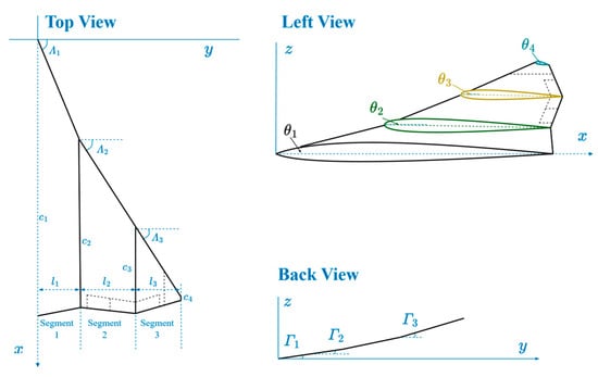
Figure 2.
Parameters defining a three-segment wing shape in the three-view projection.
3.1.2. Parameters Defining Airfoil Geometry
In this study, airfoil geometry is defined in two ways: (1) the airfoil geometry is specified directly by the NACA airfoils, including the NACA 4-digit, 5-digit and 6-series airfoils; (2) the airfoil geometry is defined using the class function/shape function transformation (CST) method by Kulfan [34], which is more flexible and versatile.
The CST method is a parametric method for airfoil description, which has been extended to the modeling of fuselage and more general cross-sectional shapes. The fundamental idea of this method is to describe the curve shape using the product of a class function and a shape function. The class function defines the basic curve classes, while the shape function modifies the curve based on the class function. Its general form is as follows:
where ψ = x/c, ξ = z/c, with c being the local chord length. The term ψN1(1 − ψ)N2 is the class function, where N1 and N2 are control parameters for the class. The term ∑bi)ψi(1 − ψ)n−i is the shape function using the Bernstein polynomial, where n is the order of the Bernstein polynomial, bi are undetermined Bernstein coefficients and ) is the binomial coefficient. The term ΔξTE = ΔzTE/c, where ΔzTE is the trailing edge thickness.
In the CST method, the airfoil profile is defined by control parameters N1 and N2, the order n for the shape function and the undetermined coefficients bi. The parameters N1 and N2 control the airfoil class. For example, N1 = 0.5 and N2 = 1 defines a NACA-type round nose and pointed aft end airfoil; N1 = 1 and N2 = 1 defines a biconvex airfoil; and N1 = 0.75 and N2 = 0.75 defines the radius distribution of a Sears–Haack body. The order n is typically set between 4 and 10 to ensure satisfactory precision for airfoil shape. The undetermined coefficients bi are related to the coordinates of the airfoil at control points, which reflect the camber and thickness distribution of the airfoil. The constraints among the leading-edge radius, boat-tail angle and bi can be found in [34]. Based on those constraints, the least squares method is applied to determine bi.
3.1.3. Parameters Defining Control Surfaces
The control surfaces include multiple elevons located along the trailing edge and all moving wing tips (AMT). These control surfaces are assumed to use the same profile of the wing element. The parameters for the elevon geometry definition are the number of elevons and the spanwise and chordwise location of each elevon. The geometric parameter for the AMT is its spanwise location.
The spanwise locations of those control surfaces are described by spanwise location ratios, as given in Equation (2). Similarly, the chordwise locations are described by chordwise location ratios at the outer y-position, as seen in Equation (3). For the control surface’s inner y-position, the chordwise location ratios are determined such that the elevon’s leading edge is parallel to the wing’s trailing edge.
where RSW is the spanwise location ratio of the control surface, including the inner ratio (j = 1) and outer ratio (j = 2), yj is the corresponding inner or outer y-position, and l is the total semi-span of the wing. The parameter RCW is the chordwise location ratio of the control surface, including the leading-edge ratio (j = 1) and trailing-edge ratio (j = 2), cj is the distance from the wing’s leading edge to the control surface’s leading or trailing edge and c is the local chord length.
3.1.4. Summary of Parameters for Wing Geometry Definition
In summary, the parameters for wing geometry definition are listed in Table 1. It should be noted that the wing reference area is defined as the projection area in the top view, as shown in Figure 2 (i.e., including the inner wing area extending to the fuselage centerline).

Table 1.
A list of parameters defining wing geometry.
3.2. Parameters Defining Fuselage Geometry
The 3D fuselage is generated based on a set of 2D curves that define the fuselage cross-sectional shape (namely, cross-sectional curves) and the fuselage longitudinal shape (namely, longitudinal curves), as depicted in Figure 3. The coordinate system for the fuselage is taken as the aircraft global coordinate system, with the x-axis parallel to the fuselage centerline and the z-axis pointing upward. In this coordinate system, the cross-sectional curves, including the curves on the upper and lower fuselage surfaces, describe key cross-section shapes in the yz-plane. The longitudinal curves consist of the upper and lower curves in the zx-plane, as well as the side curves. Once these cross-sectional and longitudinal curves are specified, the 3D fuselage geometry can be generated.
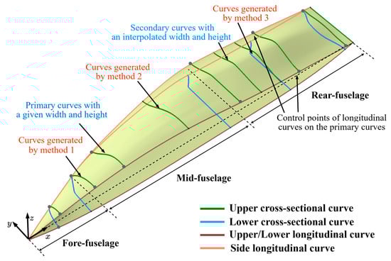
Figure 3.
Illustration for fuselage cross-sectional curves and longitudinal curves.
3.2.1. Parameters Defining Cross-Sectional Curves
In this study, the fuselage cross-sectional curves are defined for two primary purposes: (1) ensuring the geometric compatibility between the fuselage and internal layout; (2) ensuring a smooth and streamlined OML shape of the fuselage. For the first purpose, the primary cross-sectional curves are closely associated with the internal modules, such as the radar bay, cockpit and engines. Their x-positions, widths, heights and shapes are predefined in the top-level design requirements. To ensure geometric consistency between the internal layout and the fuselage shape, the x-positions of these curves are usually specified at the place where the radar bay, cockpit and engine are located. For the second purpose, the secondary cross-sectional curves are employed to help control the transition shape between those primary cross-sectional curves. In this case, only the x-positions and non-dimensional shapes of the secondary cross-sectional curves are considered, while their widths and heights are determined by the longitudinal curves (see Section 3.2.2).
The dimensions (i.e., widths and heights) and non-dimensional shapes are two fundamental parameters for defining cross-sectional curves, as shown in Figure 4. Due to the complexity of the internal layout and OML shape requirements, the non-dimensional shapes might vary significantly at different x-positions. As shown in Figure 4, the cross-sectional curves can be categorized into three types, with each type exhibiting clearly different characteristics. Accordingly, three parametric methods are used to describe the non-dimensional shapes of cross-sectional curves at different x-positions.
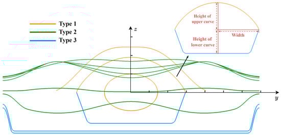
Figure 4.
Illustration for dimensions and non-dimensional shapes of fuselage cross-sectional curves.
Method 1 uses CST to define the cross-sectional curves at the fore-fuselage (see Figure 3), enabling the accommodation of regular internal modules such as the radar bay. The shape function of CST is taken as a unit function, while the class function control parameters are set as N1 = N2 = N, with N controlling the non-dimensional shape. For example, for the fore-fuselage, half of the upper cross-sectional curves defined by various values of N are shown in Figure 5a. The corresponding expression is given by
where η = y/Ws, and Ws represents the curve width.

Figure 5.
Three parametric methods defining the non-dimensional shape of fuselage cross-sectional curves: (a) half of the cross-sectional curves at the fore-fuselage; (b) half of the cross-sectional curves at the upper surface of mid- and rear-fuselage; (c) half of the cross-sectional curves at the lower surface of mid- and rear-fuselage.
Method 2 is used to describe the cross-sectional curves of the upper surface at the mid- and rear-fuselage (see Figure 3), allowing for the accommodation of the engine/nozzle and ensuring a smooth transition between the fuselage and the wing. Those curves are convex, and their tangent angles at endpoints (at η = 0 and η = 1 in Figure 5b) are constrained such that their tangent angle at η = 0 is set parallel to the y-axis and the tangent angle at η = 1 is specified to be blended smoothly with the wing. Method 2 still belongs to the CST method, in which the class function parameter N is fixed at 1, and the shape function is selected as a second-order Bernstein polynomial. To further control the non-dimensional shape of the curve, the function value of ξ(0.5) at the midpoint is introduced as the control parameter. The equation for those curves is given in Equation (5), and the shape function coefficients Ai, which represent the tangent constraints at the endpoints and the control parameter, are calculated according to Equation (6). The cross-sectional curves of the upper surface at the mid- and rear-fuselage, defined by various values of ξ(0.5) with a fixed tangent angle δ at η = 1, are shown in Figure 5b.
where Ai (i = 0, 1, 2) are the undetermined coefficients of the shape function and δ represents the tangent angle at η = 1, as shown in Figure 5b.
Method 3 is used to describe the cross-sectional curves at the lower surface of the mid- and rear-fuselage (see Figure 3), enabling the accommodation of flat internal modules, such as the weapon bay, and ensuring a smooth transition between the fuselage and the wing. These curves feature a combination of flat bottom lines and side lines. The parameters defining these curves are the angle α between the side line and the zx-plane, and the tangent angle δ at η = 1, as seen in Figure 5c. The starting point of the side line (the ending point of the flat bottom line) is determined by the side angle α. For smooth transition between flat bottom lines and side lines, the side line is defined by an interpolation spline tangent to the flat bottom line and the tangent angle δ at η = 1. The cross-sectional curves for various values of α with a fixed tangent angle δ at η = 1 are shown in Figure 5c. A larger side angle leads to a shorter flat bottom line.
3.2.2. Parameters Defining Longitudinal Curves
The fuselage longitudinal curves are determined by a set of control points. These control points are consistent with the endpoints of the primary cross-sectional curves (see Figure 3), thereby ensuring geometric compatibility between the fuselage and the internal layout. Since the lower surface primarily serves as the reference surface for positioning the internal modules, while the upper surface is adjusted to accommodate these modules, the upper longitudinal curves require more control points than the lower ones.
To achieve a streamlined fuselage, the upper and lower longitudinal curves are treated as an airfoil-like shape. Their shapes are described by N1 and N2 of the class function in the CST and a set of control points. In addition, a maximum thickness ratio, tc, defined in Equation (7), is introduced to promote a flat lower surface for weapon bay accommodation. Examples of the upper and lower longitudinal curves described with those parameters are shown in Figure 6. It is noted that the heights of these control points (the heights of fuselage cross-sectional curves) are limited within a certain range to avoid the undesired waviness.
where Hf represents the maximum distance between the lower longitudinal curve and the fuselage centerline and Lf represents the fuselage length.

Figure 6.
Fuselage longitudinal curves at the upper and lower surfaces defined by CST.
Once the side, lower and upper longitudinal curves are established, the widths and heights of the secondary cross-sectional curves are determined by the corresponding longitudinal curve along the x-positions. Specifically, the width of a secondary cross-sectional curve is obtained by intersecting its x-position plane with the side longitudinal curve and projecting the intersection line onto the xy-plane; this resulting line then defines the curve width. Similarly, the heights are determined from the intersections with the upper and lower longitudinal curves.
3.2.3. Summary of Parameters for Fuselage Geometry Definition
In summary, the parameters for fuselage geometry definition are listed in Table 2, in which the overall length of the fuselage is used to determine the absolute x-coordinates of each cross-section.
Table 2.
A List of parameters defining fuselage geometry.
3.3. Parameters Defining Propulsion Geometry
The propulsion consists of the engine, inlets and nozzle, and its geometry is depicted in Figure 7. The inlet consists of a bump compression surface with the length of L1 located in front of the inlet entrance, and an S-shaped convergent-divergent segment. This convergent-divergent segment is divided into a convergent segment (length L2) from the inlet entrance to the inlet throat, and a divergent segment (length L3) from the inlet throat to the inlet exit. The nozzle includes an S-shaped convergent segment 1 (length L4) followed by a convergent-divergent segment (length L5 + L6).
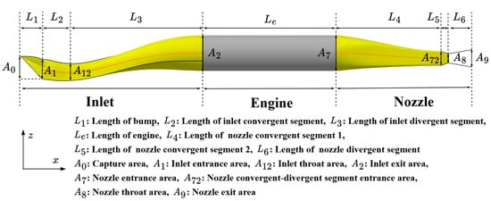
Figure 7.
Illustration of the propulsion geometry.
3.3.1. Parameters Defining Engine Size and Location
The engine shape is simplified to a cylinder. Its overall size is defined by the diameter and length. In this study, engine length ratio, defined as the ratio of the engine length to the fuselage length, is used to describe engine length relative to fuselage length.
The engine location is specified by its x, y, and z positions. The engine centerline is assumed to be parallel to the x-axis in the global coordinate system, which means that the engine centerline is parallel to the fuselage centerline. For convenience, the engine’s x-position ratio, defined as the ratio of the distance between the engine’s entrance surface and the fuselage nose to the fuselage length, is used to describe the engine’s x-position. The engine’s y-position is defined by the distance between the engine centerline and the fuselage centerline. The engine’s z-position is represented by the distance HD between the lower surface of the engine and that of the fuselage.
3.3.2. Parameters Defining Inlet Geometry
The inlet’s shape is described by the shapes of the bump compression surface, entrance lip and convergent-divergent segment, as shown in Figure 7. The parameters defining the inlet geometry are identified according to its shape generation process.
- The bump compression surface
The bump compression surface is generated based on the concept of the conical shock wave-rider [35]. It can be obtained using a streamline tracing approach based on the conical shock wave flowfield. The governing equation for the flowfield is the Taylor–Maccoll equation, given in Equation (8) [36].
where γ is the specific heat ratio, Vmax is the maximum velocity of the fluid and θ and Vr represent the polar angle and radial velocity in polar coordinates, respectively.
The streamline tracing problem is simplified to an initial value problem for ordinary differential equations. By using the velocity of the bump leading edge as the initial value, the streamlines behind the shock wave can be solved with the Runge–Kutta method. The bump compression surface is formed by those streamlines. The parameters defining bump shape are the angle and the length of the shock wave cone and bump leading edge, as shown in Figure 8 (for clarity, the z-axis direction is inverted in the figure to better display the bump shape).
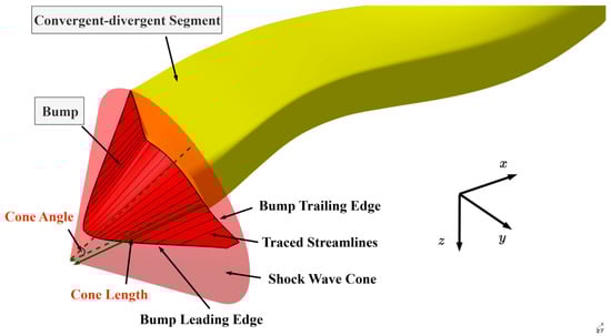
Figure 8.
Geometry of bump compression surface.
- The entrance lip
After the bump shape is generated, the next step is to design the entrance lip. The entrance lip should be designed such that, for a given capture area A0, the lip is swept forward to help push the boundary layer outboard and help the conical shock wave in sealing the inlet entrance, thus improving the inlet flow ratio. The inlet entrance is composed of the lip and the bump trailing edge. The geometry of the entrance lip is illustrated in Figure 9, in which the deflection angle of the upper lip is used to adjust the lip’s turning point and control the degree of lip forward sweep.

Figure 9.
Geometry of the entrance lip of the inlet.
The lip shape of the inlet entrance is created by the following procedure:
- A required bump width is sized to satisfy the target capture area A0, and thereby an initial lip shape is generated. The actual capture area is formed by the partial projection of the bump leading edge (controlled by the bump width) and the entrance lip. With the deflection angle of the upper lip fixed, the actual capture area varies directly with the actual bump width. Accordingly, the required bump width is calculated using the bisection method based on the target captured area A0, and the initial lip shape is thus determined.
- The initial lip shape is swept forward. The lip is divided into segments and projected onto the shock wave cone along the negative x-direction, forming a forward-swept angle on both sides.
According to the above procedure, we can see that the lip geometry is mainly determined by the capture area A0 and the deflection angle of the upper lip.
- The convergent-divergent segment
Following the lip design, the next step is to design the convergent-divergent segment. The geometry of this segment is depicted in Figure 10. Since the inlet entrance has an irregular shape (see Figure 9) and the inlet exit has a circular shape, the convergent-divergent segment has a complex transition from the irregular inlet entrance to the circular inlet exit. To generate a 3D shape of the inlet’s convergent-divergent segment, as shown in Figure 10, a series of intermediate cross-sectional curves between the inlet entrance and the inlet exit need to be designed. Those intermediate curves can be determined by three elements: (1) their non-dimensional shapes; (2) areas enclosed by those curves; (3) their centroid locations, defined by the x, y, and z coordinates in the global coordinate system.

Figure 10.
Geometry of convergent-divergent segment of the inlet.
The non-dimensional shapes of the curves are designed using a curvature-based surface generation method [37]. In this method, the non-dimensional shape of each intermediate curve is determined by its curvature function. Here, the curvature function refers to a function that defines the curvature at discretized points along the curve, with respect to the cumulative arc length from the starting discretized point. The curvature functions of the intermediate curves are interpolated based on the curvature functions of the inlet entrance and exit for a given shape distribution. Once the curvature function is obtained, a non-dimensional shape of each intermediate curve is determined. The areas enclosed by the intermediate curves can be interpolated based on the area of the inlet entrance and the area of the inlet exit for a given area distribution. Similarly, the centroid location of the intermediate curves can be interpolated based on the centroid location of the inlet entrance and the location of the exit for a given centerline offset distribution.
The distributions of shape, area and centroid location of the intermediate curves can be specified using the Lee curve [38]. The expression for the Lee curve is as follows:
where k = 1 represents the modest turning, k = 2 represents rapid turning at the end, and k = 3 represents rapid turning at the start. ψ represents the normalized x-position of each cross-section in the convergent-divergent segment. The Lee curves with different values of k are shown in Figure 11. The double-serpentine centerline can be generated by concatenating two Lee curves.

Figure 11.
Lee curves with k = 1, 2, 3.
When Equation (9) is used to define the distributions of shape, area and centerline offset of the intermediate curves, we have the following equation:
where y0, Δy and yi represent the initial values, the change relative to the initial values and the final value at the normalized x-position of each cross-section ψ, respectively. When y represents the centerline offset, the equation reflects the centerline distribution of each cross-section along the x-direction, as seen in Figure 10. When y represents the curvature function, the equation reflects the shape distribution of each cross-section along the x-direction. When y represents area, the equation reflects the area distribution of each cross-section along the x-direction.
Once the non-dimensional shape, area and centroid location of each intermediate curve are obtained, the non-dimensional shape is scaled to match its area, and each intermediate curve is positioned at its centroid and rotated to be perpendicular to the centerline, where the centerline is the line passing through the centroid of each cross-sectional curve. After that, a 3D shape of the inlet’s convergent-divergent segment can be generated based on these intermediate curves.
From the above procedure, it can be seen that the inlet’s convergent-divergent segment geometry is determined by the following parameters: its centerline offsets in y-direction and z-direction, the length of the convergent segment L2, the length of the divergent segment L3, the inlet throat area A12, the inlet exit area A2, the curvature function of the inlet exit, and the distributions of the shape, area and centerline offset (i.e., k of Lee curve).
3.3.3. Parameters Defining Nozzle Geometry
As seen in Figure 7, the nozzle consists of the convergent segment 1 and the subsequent convergent-divergent segment (including convergent segment 2 and divergent segment). The parameters defining the nozzle geometry are identified by its 3D shape-generation process.
- The convergent segment 1
The geometry of the convergent segment 1, as shown in Figure 12, is similar to that of the inlet’s convergent-divergent segment. Compared with the inlet shape, the nozzle shape is more regular and its transition surfaces are less complex. Therefore, a simpler super-ellipse method is used to generate the shapes of the nozzle’s intermediate cross-sectional curves.
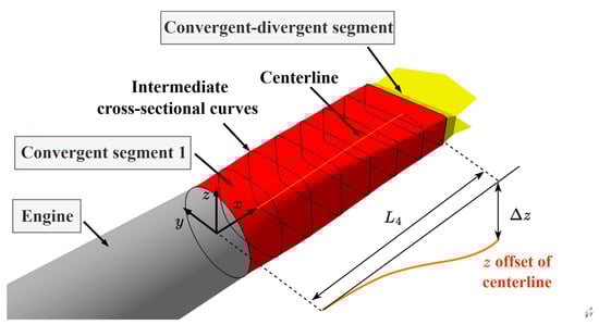
Figure 12.
Geometry of the convergent segment 1 of a nozzle.
The super-ellipse shape is formed by introducing an additional control parameter into a quadratic equation and is a family of curves that extends the ellipse. The super-ellipse is widely used in nozzle design [39]. It can be defined by the following equation:
where a and b are the lengths of the curve’s major axis and minor axis, respectively, and s is the shape control parameter of the curve.
The shape distribution of the intermediate cross-sectional curves depends on the aspect ratio and control parameter s in Equation (11) of those curves, where the aspect ratio, marked by WH, is a ratio of the curve’s width in the y-direction to its height in the z-direction. The distributions of area and centroid location of the intermediate curves are defined similarly to those of the inlet’s convergent-divergent segment.
From Figure 7 and Figure 12, the shape of the nozzle’s convergent segment 1 is defined by the following parameters: the centerline offset in the z-direction, the length of nozzle convergent segment 1 L4, the nozzle entrance area A7, the nozzle convergent-divergent segment entrance area A72, the super-ellipse parameter s, the aspect ratio WH of the convergent-divergent segment entrance curve, and the distributions of the shape, area and centerline offset (i.e., k of Lee curve).
- The convergent-divergent segment
Similarly, as shown in Figure 13, the parameters defining the convergent-divergent segment of the nozzle are the convergence angle, divergence angle, nozzle throat area A8, and nozzle exit area A9. The width of the convergent-divergent segment remains constant. Therefore, the convergent-divergent segment entrance height H72, nozzle throat height H8, and nozzle exit height H9 can be determined from the constant width and the corresponding areas. The convergent segment 2 length L5 and divergent segment length L6 can be calculated based on the heights H72, H8 and H9; the convergence angle; and the divergence angle.
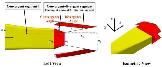
Figure 13.
Geometry of the convergent-divergent segment.
3.3.4. Summary of Parameters for Propulsion Geometry Definition
In summary, the parameters for the propulsion geometry definition are listed in Table 3.
Table 3.
A list of parameters defining propulsion geometry.
4. Approach of Master-Dependent Parameters to Entire STCA Modeling
The parameters defining the wing, fuselage and propulsion of the STCA were identified and listed in Section 3. To create a whole STCA geometric model, additional parameters are required to define the positions of the components in a global coordinate system. When all the above parameters are specified, a whole STCA geometric model can be generated. But this approach has some drawbacks:
- The geometric parameters of the wing and fuselage are specified individually. As a result, the geometric relationships at the fuselage-wing junction cannot be established, and the smooth transition between the fuselage and the wing is hardly satisfied.
- The parameters defining the fuselage and the propulsion are specified individually. When propulsion geometry is changed, the fuselage shape may not be compatible with the propulsion geometry. An example is illustrated in Figure 14, where the fuselage cannot accommodate the inlet, engine and nozzle without considering geometric relationships between the fuselage and propulsion.
 Figure 14. An example illustrating geometric incompatibility between the fuselage and propulsion.
To address the above issues, we propose an approach of master-dependent parameters based on the geometric relationships between the fuselage, the wing and the propulsion of the STCA. The idea behind this approach is rooted in geometric modeling using knowledge-based engineering [21], automatic scheme adjustment [40] and self-design approaches [41]. In our approach, the parameters in Section 3, which define the wing, the fuselage and the propulsion, are grouped into master parameters, dependent parameters and default parameters. Master parameters are the key geometric parameters that directly reflect the main geometric features in the conceptual design. Default parameters are those describing local geometric features, and their values can be predefined by the designer’s experience or tests performed beforehand. Dependent parameters are those associated with the master parameters and the default parameters through functions or design rules, and their values are automatically adjusted with those of the master parameters and default parameters.
The complete set of master, dependent and default parameters for the STCA configuration is shown in Figure 15, where arrows indicate the dependency relationship. Parameters of different components are indicated by the corresponding colors, and the arrow colors denote the component on which this parameter depends. If the color of a dependent parameter differs from that of the arrow, this means a cross-component dependency has been established.

Figure 15.
Master parameters, dependent parameters and default parameters.
The relationships among the master, dependent and default parameters explicitly reflect the design’s intent to meet specific requirements (such as the geometric compatibilities among the components) and common design rules (such as required structure depths for the accommodation of the internal modules). These relationships represent design knowledge [21] and can be updated if the design knowledge evolves. This knowledge is encoded in parametric geometry modeling. Due to the consideration of the relationships among the master, dependent and default parameters, the geometry model generated using this approach ensures a smooth transition between the fuselage and the wing, as well as a geometric integration between the fuselage and propulsion. Moreover, this approach brings an additional benefit that only the master parameters’ values need to be specified for generating the geometry model. Since the number of master parameters is much smaller compared to the number of total parameters listed in Section 3, the geometry definition is simplified to focus on the key parameters in the STCA definition, and consequently, the complexity of the optimization problem in the STCA conceptual design can be reduced.
In the following subsections, the master, dependent and default parameters are explained in detail, and their relationships are identified and formulated.
4.1. Master Parameters
The master parameters in Figure 15 serve as the key design variables in the MDAO process. From the view of airframe-propulsion integrated design, they can be categorized into two major groups:
- Airframe-related parameters: For the wing, the master parameters include semi-span, chord, leading-edge sweep angle, twist angle, dihedral angle and airfoil of each wing segment, as well as control surface parameters. These parameters together determine the wing shape of STCA. For the fuselage, the master parameters include overall length and width, as well as the heights of each fuselage cross-sectional curve. These parameters directly determine the available internal volume at different locations.
- Propulsion-related parameters: For the engine, the master parameters include the engine’s positions and size. For the inlet, the master parameters include shock wave cone angle and capture area, as well as shock wave cone x-position ratio (the ratio of the distance between the cone vertex and the fuselage nose to the fuselage length) to define the inlet entrance x-position. For the nozzle, master parameters include the throat and exit areas, which strongly influence the nozzle performance.
4.2. Default Parameters
The default parameters in Figure 15 generally have local influences on the geometry rather than significant effects on the whole configuration. Their values can be predefined by the tests performed beforehand. The default parameters can be categorized into several groups:
- Those associated with the internal layout (radar bay, cockpit, weapon bay and engine), such as the number and x-positions of fuselage cross-sectional curves, shape control parameters at fore-fuselage and the lower surface of mid-fuselage and rear-fuselage, etc.
- Those describing the local shape of the curves, such as the parameters in the CST method for defining fuselage longitudinal curve, inlet lip deflection angle, k of Lee curve, super-ellipse parameter s, aspect ratio of nozzle convergent-divergent segment, and nozzle convergence angle and divergence angle.
- Those describing local positions of the components, such as the y and z positions of the wave cone, and nozzle exit x-position ratio.
- Those describing the local size of the components, such as shock wave cone length L1, inlet convergent segment length L2, inlet throat area A12 and nozzle convergent-divergent segment entrance area A72.
Generally, the values of the default parameters remain unchanged in the conceptual design optimization, while the master parameters are considered as design variables. However, the master parameters and default parameters might be interchangeable in specific applications. As an example, the length of the shock wave cone m be treated as a master parameter if we concentrate on airframe-propulsion integrated design.
4.3. Dependent Parameters
The dependent parameters are associated with the master parameters and default parameters based on the geometric relationships among the components. For clarity, Figure 16, Figure 17 and Figure 18 illustrate the geometric relationships between the fuselage and the wing, the fuselage and the inlet and the fuselage and the nozzle.
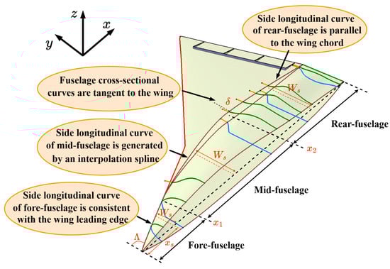
Figure 16.
Illustration of the geometric relationships between the fuselage and the wing.
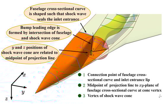
Figure 17.
Illustration of geometric relationships between the fuselage and the inlet.

Figure 18.
Illustration of geometric relationships between the fuselage and the nozzle.
The wing root chord length is equal to the fuselage length. As the vertex of the wing is aligned with the vertex of the fuselage nose, the wing root chord is consistent with the fuselage centerline for better transition, as shown in Figure 16.
The widths of fuselage cross-sectional curves depend on the leading-edge sweep angle and fuselage maximum half-width. For convenience of descriptions, the fuselage is grouped into three segments (fore-fuselage, mid-fuselage, and rear-fuselage) along the x-direction. As the side longitudinal curve of the fore-fuselage is consistent with the leading edge of the inner wing, the width of the fore-fuselage cross-sectional curves is determined by the inner wing leading-edge sweep angle. The width of the rear-fuselage cross-sectional curves is specified to be equal to the fuselage maximum half-width. For the mid-fuselage, the width of its cross-sectional curves is determined by the side longitudinal curves along the x-direction positions. Thus, the widths of the fuselage cross-sectional curves are determined by the following equation:
where Ws and xs represent the width and the x-coordinate of the fuselage cross-sectional curves, respectively. Λ represents the inner wing leading-edge sweep angle. Wf represents the fuselage maximum half-width. x1 and x2 are the x-coordinates at the starting and ending sections of the mid-fuselage, respectively. f(xs) is the y-coordinate of the interpolation spline for the middle segment of the side longitudinal curves.
The tangent angles of the fuselage cross-sectional curves depend on the wing shape, and therefore depend on all the wing master parameters. To ensure a smooth blend of the fuselage with the wing, the tangent angle (δ) of the fuselage cross-sectional curve (defined in Section 3.2.1) should be equal to the tangent angle of the intersection line between the wing and the fuselage cross-sections (see Figure 16).
The x-positions of fuselage segment points (x1 and x2) depend on the predefined positions of the cockpit and the engine. The x-positions of fuselage cross-sectional curves at the engine/nozzle depend on the x-positions ratio of the corresponding component. For the nozzle, the fuselage cross-sectional curve is positioned at the nozzle exit. For the engine, four fuselage cross-sectional curves from the engine’s entrance to its exit are set to ensure geometric compatibility; therefore, those x-positions also depend on the engine length ratio.
The required structural depth of the fuselage cross-sections depends on the cross-sectional equivalent area based on the empirical data [42]. Thus, it depends on the height, width and shape control parameters of the fuselage cross-sectional curve. The shape control parameters of the fuselage cross-sectional curves at the engine’s location depend on the engine diameter, engine z-position (HD) and engine distance (HU). To accommodate an engine with a required structural depth in the fuselage, the shape control parameter ξ(0.5) (see Section 3.2.1) is adjusted. The required structural depths for the engine are defined by two parameters (HD and HU). Here, HD is the required structural depth at the bottom of the fuselage and was defined for the engine’s z-position in Section 3.3.1, and HU is the required structural depth at the top of the fuselage, defined as the distance between the upper surface of the engine and that of the fuselage. The shape control parameters of the fuselage cross-sectional curves at the nozzle’s location depend on the nozzle’s height and the required structural depth. The nozzle height is determined by the nozzle convergent-divergent segment entrance area and the nozzle aspect ratio. The required structural depth at the nozzle’s location is obtained in the same manner as that at the engine’s location.
The bump leading edge depends on the position, size and angle of the shock wave cone, as shown in Figure 17. To achieve geometric integration between the fuselage and inlet, the bump leading edge is generated from the intersection between the fore-fuselage and the shock wave cone. In Figure 17, it is also noted that the entrance lip of the inlet serves as a part of the fuselage cross-sectional curve, ensuring an integration between the inlet and the fore-fuselage. Therefore, the parameters of the fuselage cross-sectional curve at the inlet entrance are also dependent parameters.
Since the engine entrance aligns with the inlet exit, the inlet centerline offset in the y-direction depends on the shock wave cone’s y-position and the engine’s y-position, and the inlet centerline offset in the z-direction depends on the shock wave cone’s z-position and the engine’s z-position. The inlet overall length depends on the shock wave cone’s x-position and the engine’s x-position, and therefore the length of the inlet divergent segment (L3) depends on these two parameters and the lengths of the other segments. The inlet exit curvature and the inlet exit area (A2) depend on the engine diameter.
Similarly, since the engine exit aligns with the nozzle entrance, the nozzle exit’s y-position depends on the engine’s y-position, as the 2D nozzle has no offset in the y-direction. The nozzle exit’s z-position depends on the shape control parameters of the fuselage cross-sectional curves at the nozzle, ensuring the nozzle exit shape is centered within the aft-fuselage, as shown in Figure 18. The nozzle centerline offset in the z-direction depends on the engine’s z-position and the nozzle exit’s z-position. The nozzle entrance area (A7) depends on the engine diameter. The nozzle’s overall length depends on the engine’s x-position, engine length and the nozzle’s exit x-position, so the length of nozzle divergent segment 1 (L4) depends on these three parameters and the lengths of the other nozzle segments.
5. A Tool for Parametric Geometry Modeling of STCA
Based on the method described in Section 3 and Section 4, a parametric geometry modeling tool for STCA conceptual design has been developed using a Visual Basic (VB) script in the CATIA V5 platform. This tool functions as a 3D geometric modeler and analyzer for MDAO in STCA conceptual design. The approach of master-dependent parameters is coded into the tool using a VB script. When using the tool, users simply specify values of the master parameters and the default parameters according to an STCA concept, and a 3D geometric model of the design concept is then generated automatically. Additionally, this tool can calculate geometric quantities, such as the wetted areas of the airframe and volumes of the internal bays. Those geometric quantities are usually quite concerned in STCA concept design.
The CATIA V5-based parametric aircraft geometry modeler has been adopted in the aircraft industry and in academia [21,22,43]. The benefits of the CATIA V5-based method demonstrated in our study include the following:
- CATIA V5 offers extensive geometric modeling functions, such as surface generation, Boolean operations and intersection analysis. This allows us to focus on coding for the parametric method, such as the master-dependent parameters approach, rather than dealing with complex graphical computations;
- Since CATIA V5 is widely used in the aircraft industry, the geometric models generated in CATIA V5 during the conceptual design can seamlessly transition into downstream design stages (preliminary design) by adding details to the models;
- Measurement functions in CATIA V5 make it easy to calculate the relevant geometric quantities. For example, the volumes available for the fuel tank and weapon bay can be calculated by the measurement functions when their locations are given, as shown in Figure 19;
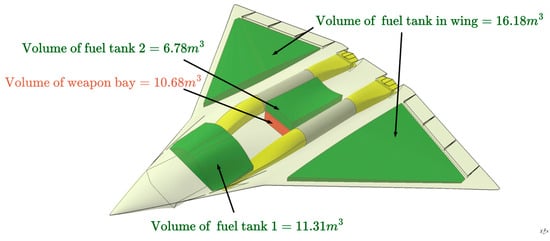 Figure 19. Volume calculation of the fuel tank and the weapon bay based on their specified locations.
- 4.
- The entrance or exit surface of the engine might be shielded by the inlet or nozzle if the inlet and nozzle have a centerline offset, which is beneficial for low observability of the propulsion. The total line-of-sights to the entrance/exit surface of the engine are grouped into those shielded and unshielded by the inlet/nozzle, as shown in Figure 20. Based on the geometric model generated in CATIA, the shielding degree of the inlet/nozzle to the engine can be measured using a specific quantity, namely the ratio of shielded line-of-sights. The shielded line-of-sights refer to the line-of-sights that are blocked by the inlet/nozzle and cannot reach the entrance/exit surface of the engine. The ratio of shielded line-of-sights is defined as a ratio of the number of shielded line-of-sights to the total number of line-of-sights, which can be calculated using a VB script in CATIA V5.
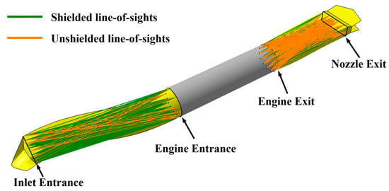 Figure 20. Line-of-sights calculation based on the inlet and nozzle geometry.
The process of generating the entire geometric model within the MDAO framework is briefly depicted in Figure 21. In this framework, the initial design variables, including the geometric master parameters, are transferred into the modeling tool. The modeling process starts with generating a wing configuration. Then, an initial fuselage is generated to be blended smoothly with the wing based on the geometric relationships between the fuselage and the wing. Next, the engine is positioned in the fuselage, followed by generating the shape of the inlet and nozzle. After that, the fuselage shape is automatically adjusted to be compatible with the propulsion geometry according to the geometric relationships between the fuselage and the propulsion (engine, inlet and nozzle). Finally, the geometric quantities, such as the ratio of the shielded line-of-sights of the inlet/nozzle to the engine, the volumes available for the fuel tank, etc., are computed. These geometric quantities, along with the entire model, are passed to the multidisciplinary design analysis (MDA). For example, the model can be used for automatic meshing and aerodynamic computations, and the geometric quantities, such as the volumes available for the fuel tank, can be used to calculate the center of gravity. The results of MDA, including the objectives and constraints defined in the optimization formulation, are subsequently passed to an optimization solver to update the design variables.
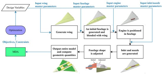
Figure 21.
Process of generating the entire geometric model within the MDAO framework.
With the CATIA V5-based VB script method, the considered constraints are ensured through the parameter dependencies by the approach of master-dependent parameters and the surface generation functions in CATIA V5. These constraints include the smooth transition between the fuselage and the wing, characterized by fuselage-wing tangent continuity, and the geometric integration between the fuselage and the propulsion. The latter is reflected in the required structural depth for accommodating the engines and nozzles, as well as the geometrical connectivity between the fuselage and the inlet/nozzle for continuous flow.
To meet the requirement of the fuselage-wing smooth transition, the tangent angles of the fuselage cross-sectional curves (defined in Section 3.2.1) should be equal to the tangent angles of the intersection line between the wing and the fuselage cross-sections. The latter angles are obtained with the “Measure” function in CATIA V5 and are assigned to the former angles in the VB script. The “Multi-Sections Surface” function in CATIA V5 is then used with these cross-sectional curves to ensure the overall surface tangent continuity.
To meet the requirement of the fuselage-propulsion geometric integration, the shape control parameters of the fuselage cross-sectional curves (defined in Section 3.2.1) are adjusted to satisfy the required structural depth, which is compared to the actual distance between the fuselage and engine (obtained with the “Measure” function in CATIA V5). Additionally, the fore-fuselage and inlet, as well as the aft-fuselage and nozzle, share the corresponding curves in CATIA V5 for geometrical connectivity.
6. Validations
The applicability of the tool developed in this study is validated with two scenarios. In Scenario 1, 3D geometric models of the STCA with different wing and fuselage configurations are generated by the tool. In Scenario 2, the impacts of the propulsion geometry on the overall configuration of the STCA are demonstrated.
6.1. Scenario 1
Two STCA configurations with different wing and fuselage configurations, namely configuration A and B, are considered in Scenario 1. Configuration A has a lambda wing planform with three wing segments. The control surfaces consist of two elevons. AMT is not adopted in this configuration. Two engines are placed near the fuselage centerline. The inlet features an S-shape in the z-direction. Its fuselage has a narrower width, in which a smaller fuel tank and weapon bay are located. The fuselage exhibits a bulging shape on its upper surface. Configuration B has a delta planform wing consisting of inner and outer wing segments. The wing has three elevons and an AMT placed at the trailing edge of the outer wing. Two engines are positioned farther from the fuselage centerline. The inlet features a combined S-shape in both the y and z directions. The fuselage width is increased to provide larger volumes for the weapon bay. The fuselage exhibits a flatter upper surface.
The values of the master parameters for the two configurations are specified in Table 4, defining the overall size of the wing and fuselage, the position and size of the engine and the main parameters of the inlet and nozzle. These values were roughly selected, with reference to the overall dimensions of an F-22-like fighter and advanced design concepts such as NGAD [32]. The values of the default parameters are specified based on tests performed beforehand, which are not listed here to save space.
Table 4.
Values of master parameters for the two configurations.
The tool successfully generated 3D geometric models of configurations A and B, as shown in Figure 22 and Figure 23, respectively. The process of modeling and calculation for each configuration takes approximately ten seconds on a workstation with an I7-14700K CPU. This time efficiency significantly supports the rapid iteration and analysis in the MDAO workflow. As seen from those figures, the fuselage is blended smoothly with the wing. To provide measurable evidence, the “Extract” function in CATIA V5 is employed to evaluate the fuselage-wing transition smoothness, as shown in Figure 24, where the tangent-continuous surfaces of configuration B are highlighted in green until extending to the tangent-discontinuous surface. From Figure 24, it can be claimed that the requirement of smooth transition between the fuselage and the wing is satisfied effectively.
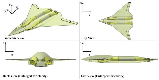
Figure 22.
Three-dimensional geometric model of configuration A, generated by the tool.

Figure 23.
Three-dimensional geometric model of configuration B, generated by the tool.

Figure 24.
Measurable evidence for proving the smooth transition between the fuselage and the wing: (a) tangent-continuous surface highlighted in green color on the upper surface of the fuselage and wing; (b) tangent-continuous surface highlighted in green color on the lower surface of the fuselage and wing.
The values of the geometric quantities of the two configurations are shown in Table 5. We can see that configurations A and B have an aspect ratio of around 2.5, but configuration B has a larger reference area. In configuration B, the engine is positioned farther from the fuselage centerline, resulting in a wider fuselage and an increase in the available fuselage volume. However, this leads to a larger fuselage wetted area. The two configurations have different inlet centerline offsets in the y and z directions. But in effect, the inlets of the two configurations have a similar ratio of shielded line-of-sights. The nozzle centerline offset of configuration A is larger than that of configuration B. Consequently, the nozzle of configuration A has a higher ratio of shielded line-of-sights.
Table 5.
Geometric quantities computed by the tool.
6.2. Scenario 2
For the STCA configuration, close relationships exist between fuselage shape, engine position, engine size and the shape of the inlet and nozzle. The engine’s position and size have a considerable impact on the shape of the fuselage and the inlet/nozzle. On the other hand, the fuselage length has a significant impact on the inlet/nozzle geometry. In this subsection, we take configuration B as a baseline to demonstrate the tool’s applicability for integrated geometric modeling of the fuselage, engine, inlet and nozzle.
6.2.1. Impact of Engine Position on the Overall Geometric Model
When the engine x-position ratio (defined in Section 3.3.1) increases from 0.54 (the baseline) to 0.59 or decreases to 0.49, the geometric models are generated as shown in Figure 25, in which the baseline model is included for comparison. Moving the engine rearward results in an increase in inlet length and a decrease in nozzle length. The increase in inlet length promotes a more gradual variation of the internal flow, but it reduces the shielding effect of the inlet to the engine. The z-coordinate of the engine centerline in the global coordinate system is adjusted slightly to maintain the required structural depth HD between the engine and the fuselage. This leads to changes in the inlet/nozzle centerline offsets in the z-direction. Additionally, the fuselage cross-sectional curves at the engine shift in the x-direction, thus affecting the cross-sectional area distribution of the fuselage along the x-direction and the supersonic wave drag. Finally, the aircraft’s center of gravity also shifts with changes in the engine’s position.
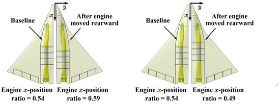
Figure 25.
Comparisons of the geometric model with changes in the engine x-position ratio.
When the engine’s y-position increases from 2 m (the baseline) to 3 m (the engine moves farther from the fuselage centerline), the fuselage maximum half-width increases from 3.5 m (baseline) to 4.1 m. Conversely, if the engine’s y-position decreases from 2 m (the baseline) to 1 m (the engine moves closer to the fuselage centerline), the fuselage’s maximum width does not need to be changed. The geometric models for different engine y-positions are shown in Figure 26. The change of the engine’s y-position results in a change in the inlet’s centerline offset in the y-direction, affecting the inlet’s ratio of shielded line-of-sights. The engine’s y-position also determines the y-direction spacing between the twin nozzles, affecting the interference drag between the twin nozzles. In addition, this change affects the shapes of the fuselage cross-sectional curves at the engine. Finally, the available volumes for the weapon bay and fuel tank in this study also relate to the engine’s y-position.
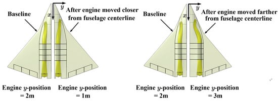
Figure 26.
Comparisons of the geometric model with changes in engine y-position.
When the engine’s z-position (defined by HD in Section 3.3.1) increases from 0.4 m (baseline) to 0.8 m, the geometric models generated after the change in HD are shown in Figure 27 and Figure 28. With an increase in HD, the engine moves upward, correspondingly leading to an increase in the inlet/nozzle centerline z-offsets, leading to a sharper variation of the internal flow and enhancing the shielding effect of both the inlet and the nozzle. The fuselage cross-sectional curves at its upper surface are more bulging, which increases the wetted area and cross-sectional area, and consequently leads to higher drag. Additionally, the available volumes for the weapon bay and fuel tank increase due to the enlarged fuselage volume.
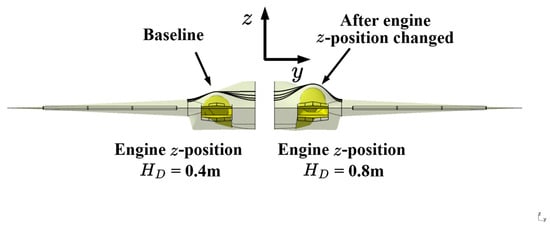
Figure 27.
Comparisons of the geometric model with a change in engine z-position HD.

Figure 28.
Comparisons of the fuselage cross-sectional curves with a change in engine z-position HD.
6.2.2. Impact of Engine Size on the Overall Geometric Model
The geometric models generated after the engine length ratio (defined in Section 3.3.1) increases from 0.22 (the baseline) to 0.25 or decreases from 0.22 to 0.19 are shown in Figure 29. In these cases, the inlet length remains unchanged because the engine x-position ratio and shock wave cone x-position ratio do not change. When the engine length ratio increases, the engine’s exit surface moves rearward, resulting in a decrease in nozzle length. This leads to a sharper variation in the nozzle internal flow while enhancing the shielding effect of the nozzle. Additionally, this change causes x-position shifts in the fuselage cross-sectional curves, thus affecting the fuselage cross-sectional area distribution along the x-direction and the supersonic wave drag. Finally, similar to the change in the engine x-position ratio, the aircraft center of gravity also shifts.

Figure 29.
Comparisons of the geometric model with changes in engine length ratio.
The geometric models generated after the engine diameter increases from 1.3 m (the baseline) to 2 m or decreases from 1.3 m to 0.6 m are shown in Figure 30 and Figure 31. When the engine diameter increases, the engine’s z-position moves upward to ensure the required depth HD. This adjustment increases the inlet/nozzle centerline offset in the z-direction, leading to a comprehensive effect on the shielding effect. Additionally, the fuselage cross-sectional curves exhibit a more bulging shape with the increase in the engine diameter, leading to a higher drag and larger volumes for the weapon bay and fuel tank, similar to the changes in the engine z-position.

Figure 30.
Comparisons of the geometric model with changes in engine diameter.
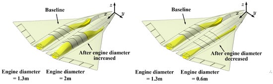
Figure 31.
Comparisons of the fuselage cross-sectional curves with changes in engine diameter.
6.2.3. Impact of Fuselage Length on the Geometry of the Inlet and the Nozzle
If there is a need to increase or decrease the lengths of the inlet and the nozzle, this can be achieved by adjusting the fuselage length. For a given engine’s x-position ratio, when fuselage length increases from 22.25 m (the baseline) to 25 m, the inlet length will increase from 6.7 m (the baseline) to 7.56 m, and the nozzle length will increase from 5 m (the baseline) to 5.6 m. Conversely, when fuselage length decreases from 22.25 m to 20 m, the inlet length will decrease from 6.7 m to 6.01 m, and the nozzle length will decrease from 5 m to 4.49 m. The geometric models generated after those changes are shown in Figure 32. From this figure, we can see that the change in the fuselage length results in changes in the overall size of the model due to parameter dependencies, affecting the shielding effect of the inlet/nozzle, the wetted area and cross-sectional area for drag and the volume for the weapon bay and fuel tank. Additionally, the wing size also changes, leading to variations in the quantities of wing, such as the reference area.
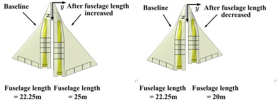
Figure 32.
Comparisons of the geometric model with changes in fuselage length.
From the demonstrations of Scenario 2, we can see that the fuselage shapes are automatically modified with changes in engine position and size, providing measurable evidence for fuselage-propulsion integration. Therefore, by using the master-dependent parameters approach, the geometric incompatibility between the fuselage and the propulsion, as shown in Figure 14, is avoided. In addition, the above examples demonstrate that engine position and size have significant impacts on fuselage shape and inlet/nozzle centerline offsets. Modifications in fuselage shape, resulting from changes in the engine, influence the zero-lift drag and, consequently, key performance, such as the maximum speed and designed combat radius. Variations in the inlet/nozzle centerline offsets in the y- or z-direction alter the shielding degree of the inlet/nozzle to the engine and, consequently, affect the low observability of the propulsion system. Also, the inlet/nozzle centerline offsets significantly affect propulsive performance. Therefore, the engine’s positions and sizes require a trade-off study from the perspective of low observability, propulsive performance, aerodynamic drag, and center of gravity, which should be performed within an MDAO framework.
7. Conclusions
This paper presents the parametric geometry modeling methodology for MDAO in the conceptual design of a notional supersonic tailless combat aircraft (STCA). The geometries of the wing, fuselage and propulsion are defined by a set of parameters. In particular, the inlet and nozzle geometries are defined with the required geometric details for aero-propulsive analysis. In this study, we propose a master-dependent parameters approach to facilitate the smooth transition between the fuselage and the wing, as well as the integration of the propulsion geometry with the fuselage. Based on the methodology, the parametric geometry tool for the conceptual design of the STCA was developed using a VB script in CATIA V5. Several case studies are used to validate the applicability of the tool. The following points are concluded:
- The tool is flexible enough to generate different configurations for the STCA, allowing early-stage comparison of alternative configurations. In addition, the tool is easy to integrate into different design frameworks due to its clear interfaces, which are defined by the list of master parameters, dependent parameters and default parameters with explicit couplings.
- The geometric models generated have the geometric characteristic that the fuselage is blended smoothly with the wing, and the tangent at the connection between the fuselage and the wing is continuous, facilitating radar cross section (RCS) reduction and allowing more accurate RCS evaluation by use of high-fidelity methods.
- The geometries of the inlet and the nozzle are defined with required geometric details and are integrated with the fuselage geometry. The geometric model with such capacity can be applied to aero-propulsive integrated analysis in the conceptual design of the STCA.
- The modeling process is simplified through the use of the tool. The case studies for the STCA modeling utilize a total of 65 geometric parameters, comprising 20 master parameters, 20 dependent parameters and 25 default parameters. By specifying only the master parameters, 3D geometric models of various STCA configurations can be generated rapidly, significantly reducing the number of design variables and, consequently, the complexity of the conceptual design optimization problem.
- The tool can calculate geometric quantities concerned in the conceptual design, such as wetted area of the wing and fuselage, the volumes available for the fuel tank and weapon bay and the ratio of shielded line-of-sights of the inlet/nozzle to the engine. These geometric quantities can be integrated into the MDAO process as constraints, allowing for rapid geometric evaluation.
It is noted that this tool focuses on modeling for the conceptual design of supersonic combat tailless aircraft. The high-lift configuration of the STCA is not considered in this tool, which will be modeled in the subsequent design phase (preliminary design). In our future work, the geometric models generated with this tool will be applied to an integrated aero-propulsive analysis and an MDAO framework in the STCA conceptual design. In the integrated aero-propulsive analysis, an Euler solver will be used to predict aerodynamic performance, and a zero-dimensional steady thermodynamics analysis model will be used to estimate propulsive performance. The MDAO framework will include modules of geometry, aerodynamics, propulsion, weight, performance, RCS, control and stability, with the geometry module serving as the foundation for other modules.
Author Contributions
Conceptualization, J.X. and X.Y.; methodology, J.X. and X.Y.; software, J.X.; validation, J.X.; formal analysis, J.X.; investigation, J.X.; resources, J.X.; data curation, J.X.; writing—original draft preparation, J.X.; writing—review and editing, J.X. and X.Y.; visualization, J.X.; supervision, X.Y.; project administration, X.Y.; funding acquisition, X.Y. All authors have read and agreed to the published version of the manuscript.
Funding
This research received no external funding.
Data Availability Statement
The data presented in this study are available from the corresponding author upon request.
DURC Statement
Current research is limited to the parametric geometry modeling methodology for the supersonic tailless combat aircraft, which is beneficial for configuration exploration at the conceptual design stage and does not pose a threat to public health or national security. Authors acknowledge the dual-use potential of the research involving parametric geometry modeling methodologies for the supersonic aircraft conceptual design and confirm that all necessary precautions have been taken to prevent potential misuse. As an ethical responsibility, authors strictly adhere to relevant national and international laws about dual-use research of concern (DURC). Authors advocate for responsible deployment, ethical considerations, regulatory compliance, and transparent reporting to mitigate misuse risks and foster beneficial outcomes.
Conflicts of Interest
The authors declare no conflicts of interest.
Abbreviations
The following abbreviations are used in this manuscript:
| MDAO | Multidisciplinary Design Analysis Optimization |
| GGG | General Geometry Generator |
| RAGE | Rapid Geometry Engine |
| OML | Outer Mold Line |
| KBE | Knowledge-Based Engineering |
| ESP | Engineering Sketch Pad |
| ESAV | Efficient Supersonic Air Vehicle |
| CST | Class function/Shape function Transformation |
| STCA | Supersonic Tailless Combat Aircraft |
| RCS | Radar Cross Section |
| MLFMM | Multilevel Fast Multipole Method |
| PO | Physical Optics |
| NGAD | Next Generation Air Dominance |
| DSI | Diverterless Supersonic Inlet |
| 2D | Two Dimensional |
| 3D | Three Dimensional |
| AMT | All-Moving Wing Tips |
| VB | Visual Basic |
| MDA | Multidisciplinary Design Analysis |
References
- Friehmelt, H. Thrust Vectoring and Tailless Aircraft Design-Review and Outlook. In Proceedings of the 21st Atmospheric Flight Mechanics Conference, San Diego, CA, USA, 29–31 July 1996. [Google Scholar]
- Tirpak, J.A. The Sixth Generation Fighter. Air Force Mag. 2009, 92, 38–42. [Google Scholar]
- Takahashi, T.T.; Kady, C.T. Planform Selection for an Efficient Supersonic Air Vehicle. In Proceedings of the 14th AIAA Aviation Technology, Integration, and Operations Conference, Atlanta, GA, USA, 16–20 June 2014. [Google Scholar]
- Wang, Z.; Hu, L.; Fei, W.; Zhou, D.; Yang, D.; Ma, C.; Gong, Z.; Wu, J.; Zhang, C.; Yang, Y. High-Performance Attitude Control Design of Supersonic Tailless Aircraft: A Cascaded Disturbance Rejection Approach. Aerospace 2023, 10, 198. [Google Scholar] [CrossRef]
- Davies, C.; Stelmack, M.; Zink, P.S.; De La Garza, A.; Flick, P. High Fidelity MDO Process Development and Application to Fighter Strike Conceptual Design. In Proceedings of the 12th AIAA Aviation Technology, Integration, and Operations (ATIO) Conference and 14th AIAA/ISSMO Multidisciplinary Analysis and Optimization Conference, Indianapolis, IN, USA, 17–19 September 2012. [Google Scholar]
- Hurwitz, W.; Donovan, S.; Camberos, J.; German, B. A Systems Engineering Approach to the Application of Multidisciplinary Design, Analysis and Optimization (MDAO) for Efficient Supersonic Air-Vehicle Exploration (ESAVE). In Proceedings of the 12th AIAA Aviation Technology, Integration, and Operations (ATIO) Conference and 14th AIAA/ISSMO Multidisciplinary Analysis and Optimization Conference, Indianapolis, IN, USA, 17–19 September 2012. [Google Scholar]
- Allison, D.; Morris, C.; Schetz, J.; Kapania, R.; Sultan, C.; Deaton, J.; Grandhi, R. A Multidisciplinary Design Optimization Framework for Design Studies of an Efficient Supersonic Air Vehicle. In Proceedings of the 12th AIAA Aviation Technology, Integration, and Operations (ATIO) Conference and 14th AIAA/ISSMO Multidisciplinary Analysis and Optimization Conference, Indianapolis, IN, USA, 17–19 September 2012. [Google Scholar]
- Jasa, J.P.; Brelje, B.J.; Gray, J.S.; Mader, C.A.; Martins, J.R.R.A. Large-Scale Path-Dependent Optimization of Supersonic Aircraft. Aerospace 2020, 7, 152. [Google Scholar] [CrossRef]
- Nicolai, L.M.; Carichner, G. Fundamentals of Aircraft and Airship Design; American Institute of Aeronautics and Astronautics: Reston, VA, USA, 2010; pp. 23–26. [Google Scholar]
- Samareh, J.A. Status and Future of Geometry Modeling and Grid Generation for Design and Optimization. J. Aircr. 1999, 36, 97–104. [Google Scholar] [CrossRef]
- Agarwal, D.; Marques, S.; Robinson, T.T. Aerodynamic Shape Optimisation Using Parametric CAD and Discrete Adjoint. Aerospace 2022, 9, 743. [Google Scholar] [CrossRef]
- McDonald, R.A.; Gloudemans, J.R. Open Vehicle Sketch Pad: An Open Source Parametric Geometry and Analysis Tool for Conceptual Aircraft Design. In Proceedings of the AIAA SCITECH 2022 Forum, San Diego, CA, USA & Virtual, 3–7 January 2022. [Google Scholar]
- Garcia, J.A.; Bowles, J.V.; Kinney, D.J.; Melton, J.E.; Jiang, X.J. VIPER Integrated MDAO Analysis for Conceptual Design of Supersonic X-Plane Vehicles; NASA/TM-2019-220239; NASA: Washington, DC, USA, 2019. [Google Scholar]
- Ghoman, S.S.; Sarhaddi, D.; Wang, Z.; Chen, P. ModelCenter-Integrated Reduced Order Multi-Fidelity Optimization Scheme for NASA MDAO Framework. In Proceedings of the 54th AIAA/ASME/ASCE/AHS/ASC Structures, Structural Dynamics, and Mate-rials Conference, Boston, MA, USA, 8–11 April 2013. [Google Scholar]
- Hwang, J.; Martins, J.R.R.A. GeoMACH: Geometry-Centric MDAO of Aircraft Configurations with High Fidelity. In Proceedings of the 12th AIAA Aviation Technology, Integration, and Operations (ATIO) Conference and 14th AIAA/ISSMO Multidisciplinary Analysis and Optimization Conference, Indianapolis, IN, USA, 17–19 September 2012. [Google Scholar]
- Heath, C.; Gray, J. OpenMDAO: Framework for Flexible Multidisciplinary Design, Analysis and Optimization Methods. In Proceedings of the 53rd AIAA/ASME/ASCE/AHS/ASC Structures, Structural Dynamics and Materials Conference, Honolulu, HI, USA, 23–26 April 2012. [Google Scholar]
- Vandenbrande, J.; Grandine, T.; Hogan, T. The Search for the Perfect Body: Shape Control for Multidisciplinary Design Optimization. In Proceedings of the 44th AIAA Aerospace Sciences Meeting and Exhibit, Reno, NV, USA, 9–12 January 2006. [Google Scholar]
- Rodriguez, D.; Sturdza, P. A Rapid Geometry Engine for Preliminary Aircraft Design. In Proceedings of the 44th AIAA Aerospace Sciences Meeting and Exhibit, Reno, NV, USA, 9–12 January 2006. [Google Scholar]
- Siggel, M.; Kleinert, J.; Stollenwerk, T.; Maierl, R. TiGL-An Open Source Computational Geometry Library for Parametric Aircraft Design. Math. Comput. Sci. 2019, 13, 367–389. [Google Scholar] [CrossRef]
- Nagel, B.; Böhnke, D.; Gollnick, V.; Schmollgruber, P.; Rizzi, A.; La Rocca, G.; Alonso, J.J. Communication in Aircraft Design: Can We Establish a Common Language. In Proceedings of the 28th International Congress of the Aeronautical Sciences, Brisbane, QLD, Australia, 23–28 September 2012. [Google Scholar]
- Munjulury, R.C.; Staack, I.; Berry, P.; Krus, P. A Knowledge-Based Integrated Aircraft Conceptual Design Framework. CEAS Aeronaut. J. 2016, 7, 95–105. [Google Scholar] [CrossRef]
- Banerjee, S.K.; Thomas, P.; Cai, X. CATIA V5-Based Parametric Aircraft Geometry Modeler. SAE Int. J. Aerosp. 2013, 6, 311–321. [Google Scholar] [CrossRef]
- Meckstroth, C.M. Parameterized, Multi-Fidelity Aircraft Geometry and Analysis for MDAO Studies Using CAPS. In Proceedings of the AIAA Scitech 2019 Forum, San Diego, CA, USA, 7–11 January 2019. [Google Scholar]
- Haimes, R.; Dannenhoffer, J. The Engineering Sketch Pad: A Solid-Modeling, Feature-Based, Web-Enabled System for Building Parametric Geometry. In Proceedings of the 21st AIAA Computational Fluid Dynamics Conference, San Diego, CA, USA, 24–27 June 2013. [Google Scholar]
- Morris, C.C.; Allison, D.L.; Schetz, J.A.; Kapania, R.K.; Sultan, C. Parametric Geometry Model for Design Studies of Tailless Supersonic Aircraft. J. Aircr. 2014, 51, 1455–1466. [Google Scholar] [CrossRef]
- Alyanak, E. Modeling for Conceptual Design: An Aeroelastic Approach. In Proceedings of the 53rd AIAA/ASME/ASCE/AHS/ASC Structures, Structural Dynamics and Materials Conference, Honolulu, HI, USA, 23–26 April 2012. [Google Scholar]
- Alyanak, E.; Kolonay, R. Efficient Supersonic Air Vehicle Structural Modeling for Conceptual Design. In Proceedings of the 12th AIAA Aviation Technology, Integration, and Operations (ATIO) Conference and 14th AIAA/ISSMO Multidisciplinary Analysis and Optimization Conference, Indianapolis, IN, USA, 17–19 September 2012. [Google Scholar]
- Straathof, M.H.; Koren, B. Aerodynamic Shape Parameterisation and Optimisation of Novel Configurations. In Proceedings of the 2008 Royal Aeronautical Society Annual Applied Aerodynamics Research Conference, London, UK, 27–28 October 2008. [Google Scholar]
- Allison, D.L.; Alyanak, E.J. Development of Installed Propulsion Performance Model for High-Performance Aircraft Conceptual Design. In Proceedings of the 15th AIAA/ISSMO Multidisciplinary Analysis and Optimization Conference, Atlanta, GA, USA, 16–20 June 2014. [Google Scholar]
- Allison, D.L.; Alyanak, E.J.; Bhagat, N.D. High Fidelity, Nonlinear, Integrated Nozzle Installation Effects for Numerical Propulsion System Simulation. In Proceedings of the 56th AIAA/ASCE/AHS/ASC Structures, Structural Dynamics, and Materials Conference, Kissimmee, FL, USA, 5–9 January 2015. [Google Scholar]
- Torenbeek, E. Advanced Aircraft Design: Conceptual Design, Analysis, and Optimization of Subsonic Civil Airplanes; John Wiley & Sons: Chichester, West Sussex, UK, 2013; pp. 140–149. [Google Scholar]
- Next Generation Air Dominance. Available online: https://en.wikipedia.org/w/index.php?title=Next_Generation_Air_Dominance&oldid=1313686237 (accessed on 27 November 2025).
- Gridley, M.; Cahill, M. ACIS Air Induction System Trade Study. In Proceedings of the 32nd Joint Propulsion Conference and Exhibit, Lake Buena Vista, FL, USA, 1–3 July 1996. [Google Scholar]
- Kulfan, B.M. Universal Parametric Geometry Representation Method. J. Aircr. 2008, 45, 142–158. [Google Scholar] [CrossRef]
- Gridley, M.C.; Walker, S.H. Inlet and Nozzle Technology for 21st Century Fighter Aircraft. In Proceedings of the ASME 1996 International Gas Turbine and Aeroengine Congress and Exhibition, Birmingham, UK, 10–13 June 1996. [Google Scholar]
- Anderson, J.D. Fundamentals of Aerodynamics, 6th ed.; McGraw-Hill Education: New York, NY, USA, 2017; pp. 858–865. [Google Scholar]
- Zhou, H.C.; Tan, H.J.; Li, X.P. Unique Design Method of Subsonic Inlet with Complex Cross-sectional Shape. J. Aerosp. Power 2009, 24, 1357–1363. (In Chinese) [Google Scholar]
- Lee, C.; Boedicker, C. Subsonic Diffuser Design and Performance for Advanced Fighter Aircraft. In Proceedings of the Aircraft Design Systems and Operations Meeting, Colorado Springs, CO, USA, 14–16 October 1985. [Google Scholar]
- Burley, J.R., II; Carlson, J.R. Circular-to-Rectangular Transition Ducts for High-Aspect Ratio Nonaxisymmetric Nozzles. In Proceedings of the 21st Joint Propulsion Conference, Monterey, CA, USA, 8–10 July 1985. [Google Scholar]
- Liu, H.; Wu, Z.; Raymer, D.P. Automated Scheme Adjustment for Conceptual Aircraft Design and Optimization. J. Aircr. 2006, 43, 825–831. [Google Scholar] [CrossRef]
- Sobester, A. Self-Designing Parametric Geometries. In Proceedings of the 56th AIAA/ASCE/AHS/ASC Structures, Structural Dynamics, and Materials Conference, Kissimmee, FL, USA, 5–9 January 2015. [Google Scholar]
- Roskam, J. Airplane Design; Roskam Aviation and Engineering Corporation: Lawrence, KS, USA, 1985; pp. 108–109. [Google Scholar]
- Carty, A.; Davies, C. Fusion of Aircraft Synthesis and Computer Aided Design. In Proceedings of the 10th AIAA/ISSMO Multidisciplinary Analysis and Optimization Conference, Albany, NY, USA, 30 August–1 September 2004. [Google Scholar]
Disclaimer/Publisher’s Note: The statements, opinions and data contained in all publications are solely those of the individual author(s) and contributor(s) and not of MDPI and/or the editor(s). MDPI and/or the editor(s) disclaim responsibility for any injury to people or property resulting from any ideas, methods, instructions or products referred to in the content. |
© 2025 by the authors. Licensee MDPI, Basel, Switzerland. This article is an open access article distributed under the terms and conditions of the Creative Commons Attribution (CC BY) license.