Abstract
Accurate kinematic parameter identification is essential for space manipulators to attain millimeter-level positioning accuracy and robust motion control. This study develops a universal strategy for comprehensive parameter identification by establishing a generalized geometric error model using Denavit–Hartenberg (DH) parameterization. For robotic calibration, the Fibonacci spiral sampling technique optimizes pose selection, ensuring end-effector poses fully cover the manipulator’s workspace to enhance identification convergence. By combining the local convergence capability of the Levenberg–Marquardt (LM) algorithm with the global search characteristics of Particle Swarm Optimization (PSO), we propose a novel hybrid PSO-LM optimization algorithm, achieving synergistic enhancement of global exploration and local refinement. An experimental platform using a laser tracker as the metrology reference was constructed, with a 6-degree-of-freedom (6-DOF) space manipulator selected as a validation case. Experimental results demonstrate that the proposed method significantly reduces the average positioning error from 10.87 mm to 0.47 mm, achieving a 95.7% improvement in relative accuracy. These findings validate that the parameter identification approach can precisely determine the actual geometric parameters of space manipulators, providing critical technical support for high-precision on-orbit operations.
1. Introduction
Precise kinematic parameter identification is critical for space robotics. Space manipulators are critical components in aerospace systems, and their positioning accuracy directly determines the success of on-orbit missions. As the core executive unit for high-value on-orbit services such as satellite capture and module replacement, the absolute positioning accuracy of space manipulators directly determines mission success. However, kinematic parameters are subject to temporal deviations due to manufacturing and assembly tolerances, severe vibrational and shock loads during launch, and extreme thermal fluctuations in orbit [1,2,3]. These space-specific environmental factors lead to deviations between the actual kinematic model and the theoretical model, making high-precision calibration an urgent technical bottleneck that must be overcome for space applications. In-depth analyses reveal that the time-varying characteristics of kinematic parameters demonstrate Multiphysics coupled features: these encompass not only geometric error propagation during manufacturing processes but also parameter drift induced by complex dynamic loads (e.g., broadband vibrations, transient shocks, and noise disturbances) during launch phases, and further involve parameter mismatch caused by disparities between terrestrial gravity and spaceborne microgravity/thermal cycling environments [4,5,6,7]. These variations render preconfigured motion control parameters ineffective, compromising the manipulator’s operational precision [8,9]. Thus, developing a generalized, efficient, and accurate kinematic parameter identification method for space manipulators is both urgent and imperative.
Space robotic manipulators, as critical components of spacecraft, play a pivotal role in on-orbit servicing, satellite capture, and space station assembly missions. The space robotic system demonstrates positioning accuracy at the millimeter to submillimeter scale [10,11,12]. Representative applications include the Special Purpose Dexterous Manipulator (SPDM) developed by Canada for fine manipulation and payload handling [13]; the Robot Technology Experiment (ROTEX) by the German Aerospace Center (DLR) for object grasping and plug-in tasks [14]; and the NASA-developed SPIDER for extravehicular inspection and repair [15].
Space manipulators operate in fundamentally distinct environments compared to terrestrial industrial robots, with microgravity being the most prominent distinguishing condition [16,17]. Although kinematic parameters are inherently geometric properties and thus independent of gravitational influence, the parameter identification process is indirectly affected by gravity-dependent factors. These include variations in joint friction characteristics, structural deformations due to self-weight loading, and dynamic coupling effects between links. Consequently, these environment-specific considerations necessitate the development of specialized calibration methodologies for space applications. Nevertheless, the fundamental methodology for kinematic parameter identification remains universally valid across different operational environments, as it addresses the core mathematical relationship between joint coordinates and end-effector pose. Since the 1980s, research on improving robotic manipulator accuracy through kinematic parameter identification has advanced significantly Since the 1980s, research on improving robotic manipulator accuracy through kinematic parameter identification has advanced significantly [18,19]. The identification process generally involves four steps: error modeling, data measurement, parameter identification, and compensation verification. Two dominant kinematic modeling methods are the DH method [20] and screw theory [21,22]. The DH method uses four parameters to describe transformations between adjacent links, offering intuitiveness and computational efficiency, making it an industrial standard for serial manipulator calibration. In contrast, screw theory, as comprehensively presented in the modern robotics framework by Lynch and Park [22], describes rigid-body motions using exponential coordinates and the product of exponentials formula. While it excels in parallel mechanism modeling and singularity analysis, and provides a globally parameterization-free framework that avoids the singularities inherent to some DH conventions, it offers less immediate physical interpretability of its parameters and often requires higher computational complexity than the DH method for the specific application of parameter identification in serial manipulators, which is the focus of this work. The well-established physical interpretability of DH parameters is particularly beneficial for analyzing error sources and implementing practical compensation in engineering applications.
For measurement, laser trackers [23] and vision systems [24] are most common. Vision systems enable non-contact measurement but suffer performance degradation under extreme lighting, high radiation, or shadows—common in space—and impose high computational costs, challenging real-time on-orbit use. Laser trackers, with high accuracy and large-range dynamic tracking, are often preferred for space manipulator calibration. For example, Dzubba [25] used a laser tracker to calibrate a KUKA robot, reducing average positioning error by 54.9% with a feedforward compensation model, highlighting the critical role of kinematic parameter identification.
Kinematic parameter identification is inherently a nonlinear optimization problem. To comprehensively evaluate the performance of various algorithms, a systematic comparative analysis of classical calibration methods, evolutionary optimization algorithms, and hybrid approaches is essential. Established techniques include Least Squares (LS), the Levenberg–Marquardt (LM) algorithm, Backpropagation (BP) Neural Networks, Kolmogorov-Arnold Networks (KAN), and standard Particle Swarm Optimization (PSO). As one of the earliest methods applied to kinematic calibration, LS gained widespread adoption due to its computational simplicity. However, its identification accuracy is susceptible to measurement noise and model linearization errors, often leading to convergence to local optima. Antonelli et al. [26] developed an LS-based calibration method for mobile robots and experimentally validated its effectiveness. To address persistent accuracy degradation in industrial robots post-calibration, [27] introduced a continuous calibration approach utilizing Recursive Least Squares (RLS), enhancing both precision and efficiency.
Evolutionary optimization algorithms, such as standard PSO and Genetic Algorithms (GA), exhibit strong global search capabilities and are effective in handling nonlinear problems. Reference [28] formulated a DH parameter error model and solved it using GA, with experimental validation. Reference [29] proposed an information-value-based PSO method for incremental parameter identification. Yu et al. [30] developed an enhanced PSO variant that improved average positioning accuracy by 22.26% compared to LS. Nevertheless, these algorithms generally suffer from slow convergence rates and high computational costs, posing significant challenges for real-time on-orbit applications. In recent years, hybrid optimization strategies have demonstrated increasing promise. Deng et al. [31] combined the LM algorithm with particle filtering for kinematic parameter identification, exemplifying the hybrid methodology. Hang et al. [32] pioneered the application of KAN to power system parameter identification, achieving a 5% error reduction, while a hybrid LS-KAN model further decreased the mean absolute error to below 0.412% in lithium-ion battery health monitoring [33]. Neural Networks (NN) have also been employed for kinematic parameter identification in hybrid serial-parallel manipulators [34], and Huber et al. [35] leveraged NNs to solve inverse parameter identification problems, establishing explicit relationships among strain, stress, time, and material parameters. These hybrid methods integrate global search with local refinement, aiming to enhance convergence efficiency while maintaining identification accuracy.
Kinematic parameter identification serves as the foundation for high-precision control of space manipulators. Although the microgravity environment alters dynamic characteristics, such as joint friction and structural flexibility, the kinematic parameters themselves are geometric properties. Consequently, the core logic of the identification algorithm remains consistent and is independent of the operational environment. Therefore, validating the core algorithm’s effectiveness on ground is a essential prerequisite before its application in any complex environment, including advanced ground-testing facilities or the actual on-orbit setting [36].The hybrid PSO-LM algorithm proposed in this study aims to provide a superior solution to this universal problem, with its ground-based verification constituting the cornerstone for future space applications.
Despite these advances, existing hybrid methods remain insufficiently robust and generalizable when applied to the strongly coupled, highly nonlinear parameter identification problems inherent in space manipulators. While LS tends to converge to local optima, LM is sensitive to initial values, NNs demand substantial training data, and standard PSO entails high computational cost. To address these limitations, this work proposes a PSO-LM hybrid algorithm that synergistically combines the global exploration capacity of PSO with the rapid local convergence of LM. This approach provides a more accurate and efficient parameter identification solution tailored to space manipulators, addressing the critical need for highly efficient and precise algorithms designed for space applications.
Space manipulators present unique challenges for on-orbit parameter identification, including limited calibration sampling points, strongly coupled DH parameters, and highly nonlinear characteristics. To address these challenges, this study focuses on three key aspects:
- Establishment of a generalized kinematic parameter identification framework
To address the common requirements for parameter calibration of heterogeneous manipulator configurations, this study aims to develop a generalized identification framework independent of specific structures. By integrating sampling strategy optimization with intelligent optimization theory, we establish a highly accurate parameter identification methodology with broad adaptability.
- 2.
- An efficient DH parameter identification method for space manipulators
Focusing on the special operational conditions and precision requirements of space manipulators during on-orbit operations, this paper proposes an efficient DH parameter identification algorithm through systematic analysis of existing methods’ limitations. The proposed algorithm optimizes both sampling strategies and computational architecture, significantly improving identification efficiency while effectively accommodating engineering constraints such as limited sampling points and stringent real-time requirements for on-orbit calibration.
- 3.
- Spatial analysis-based optimized sampling theory
Moving beyond traditional empirical pose sampling paradigms, we develop a mathematically guaranteed theory for optimal sampling point distribution based on workspace geometric characteristics. This theory provides optimal excitation conditions for parameter identification, fundamentally enhancing the numerical stability and convergence efficiency of the calibration process.
The paper is organized as follows: Section II formulates the geometric error model and identification strategy; Section III presents the simulation framework for multi-algorithm evaluation; Section IV details the PSO-LM hybrid algorithm; Section V introduces Fibonacci spiral-based sampling; Section VI validates the method experimentally; and Section VII concludes the work.
2. Establishment of Geometric Error Model
On-orbit operations exhibit high complexity and significant operational uncertainty. The degrees of freedom (DOF) configuration of space manipulators is determined by their design objectives and mission requirements. While 6 or 7 DOF designs are commonly adopted to achieve arbitrary end-effector positioning and orientation in three-dimensional space, additional DOF may be required for complex specialized tasks to enhance obstacle avoidance capabilities and optimize motion trajectories. The development of a universal geometric error model for space manipulators has become an urgent research priority.
To analyze the impact of kinematic parameter errors on end-effector positioning accuracy, a mathematical model is required that describes positioning errors as functions of kinematic parameter deviations. This study employs the DH convention for modeling, which effectively characterizes the spatial transformation relationships between adjacent links and is particularly suitable for forward/inverse kinematics analysis of serial manipulators [37]. The end-effector pose is computed through consecutive transformations:
where
represents the homogeneous transformation matrix of the
-th link coordinate frame relative to the (
)-th link coordinate frame.
The positional components are obtained from the transformation matrix:
where
denotes the element at row
, column
of the matrix. The manipulator’s end-effector position can be represented as a function of kinematic parameters:
where the ideal position is given by forward kinematics with nominal parameters. Considering DH parameter errors (,
,
,
), the actual position becomes:
The mapping between joint velocities and end-effector velocities of a manipulator is derived through velocity-level kinematics, where errors in each DH parameter induce deviations in the end-effector position. By formulating the differential kinematics, the Jacobian matrix is computed to establish a linear relationship between geometric parameter errors
and positional errors
,which can be simplified as:
where
is the (3 × 4n) Jacobian matrix of position with respect to DH parameters
is the (4n × 1) parameter error vector
The established geometric error model provides the theoretical framework for parameter identification. Chapter III develops a comprehensive kinematic parameter identification strategy.
3. Kinematic Parameter Identification Strategy
The kinematic error model of the space manipulator is formulated such that each end-effector pose corresponds to a set of kinematic error equations [38]. By collecting approximately
sets of end-effector position measurements, we construct
kinematic error equations to solve for the
DH parameters
across
joints. The post-calibration positional error is:
The calibrated positional error is denoted as
, representing the residual deviation between the measured and model-predicted end-effector positions after kinematic parameter identification.
: The calibrated end-effector position computed using the updated kinematic model. To meet the task requirements and control precision specifications of the manipulator, the following conditions must be satisfied for pre and post-calibration errors:
represents the absolute error threshold, which specifies the maximum permissible deviation for the manipulator.
The closed-loop optimization framework for robotic arm kinematic calibration, as illustrated in Figure 1, establishes a systematic parameter identification and validation process. First, sampling points are arranged according to the optimal sampling strategy. Then, when the desired end-effector pose
is commanded to the manipulator system, high-precision metrology equipment measures the actual achieved pose
from which the initial positional deviation
is computed to quantify current kinematic model inaccuracies. This deviation metric serves as the basis for subsequent parameter corrections, where a precise mapping between geometric parameter errors and end-effector pose deviations is established to generate systematic DH parameter adjustments.
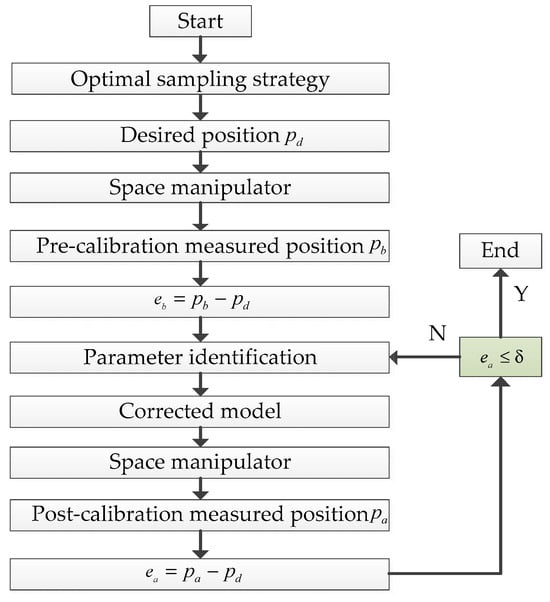
Figure 1.
Iterative flowchart of kinematic parameter identification.
Following parameter calibration, validation motions are executed to acquire updated pose measurements
, enabling evaluation of residual errors
. The iterative optimization process continues until meeting two key convergence criteria: stabilization of error reduction, where the relative change between successive iterations satisfies the threshold defined in Equation (8). This rigorous approach ensures both the relative improvement of calibration effectiveness and the absolute positioning accuracy required for precision robotic operations.
4. Hybrid PSO-LM Algorithm for Parameter Identification
4.1. Hybrid PSO-LM Algorithm
PSO is a population-based global optimization algorithm inspired by the collective behavior of biological systems such as bird flocks or fish schools [39]. The LM method is an iterative technique for nonlinear least-squares optimization that combines the global convergence properties of gradient descent with the local fast convergence of Gauss-Newton [40]. PSO avoids local optima through swarm intelligence mechanisms, albeit with slower convergence rates, whereas the LM algorithm achieves quadratic convergence when initial estimates reside in the basin of attraction of the global optimum, demonstrating strong dependence on initial parameter selection.
This study proposes a novel PSO-LM cooperative algorithm that synergistically combines the local convergence capability of LM with the global exploration characteristics of PSO, enhance identification accuracy and computational efficiency. This hybrid strategy is specifically designed to address the unique challenges of space manipulator calibration: the PSO component provides robust global search capability to handle strong parameter coupling and limited sampling points available on-orbit, while the LM component enables rapid local convergence to meet the stringent requirements for computational efficiency and speed in spaceborne processors.
The kinematic parameter identification problem can be transformed into an optimization problem of the objective function, whose core lies in adjusting model parameters through optimization algorithms to minimize the error between theoretical model outputs and actual observed data. The objective function is constructed as follows:
where
denotes the number of sampling points.
The goal is to find the optimal parameters
that minimize the objective function:
This metaheuristic technique employs cooperative search mechanisms within the parameter space to locate optimal solutions. Each particle represents a 4n-dimensional vector of DH parameters.
Initially, the PSO algorithm initializes a swarm of
particles to perform global exploration within the parameter space.
To balance computational efficiency while ensuring at least 5 particles per dimension for effective exploration, the swarm size
for a 4n-dimensional DH parameter optimization problem is typically set to:
Through iterative updates of particle positions and velocities, the optimal solution is selected based on fitness evaluation and serves as the initial value for the subsequent LM algorithm.
The velocity update rule governing particle motion is formulated as:
where
is the velocity vector of particle
represents a linearly decreasing inertia weight
and
are cognitive and social learning factors respectively
denotes the historical best solution of particle
and
are drawn independently from
represents the global historical best solution
The position update rule governing particle motion is formulated as:
where
represents the updated position vector of particle
at iteration
denotes the current position of particle
is the velocity vector computed from Equation (13)
The termination criteria are triggered when either the maximum iteration count
is reached or the condition
is satisfied, where
denotes the transition scaling factor between PSO and LM phases.
The optimal solution
output from PSO serves as the initial parameter vector
for subsequent LM refinement.
The LM algorithm then refines the parameters via Jacobian matrix computation and adaptive damping factor adjustment to achieve rapid local convergence.
The LM update rule is:
where
is the Jacobian matrix of residuals
denotes the identity matrix
The damping factor
is adaptively regulated:
If
: update
to
If
, update
to
, then recompute the step size.
The identification process terminates when
is satisfied. If the PSO-LM algorithm converges, the optimal parameter solution is output. Otherwise, the current optimization results are fed back to the PSO process, where particles with poorer fitness are replaced, and new particles are generated in the neighborhood of the current solution to restart the global search.
The workflow of the PSO-LM hybrid optimization algorithm, as illustrated in Figure 2, adopts a modular two-phase design. Initially, the PSO algorithm (gray module) performs global exploration in the 4n-dimensional parameter space, where the swarm is initialized and iteratively updated through position and velocity adjustments. During this phase, individual best solutions (
) and the global best solution (
) are continuously refined based on fitness evaluation until either the error threshold
or the maximum iteration count
is met.
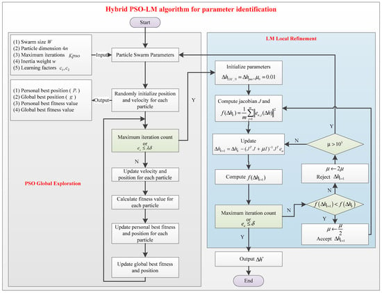
Figure 2.
Flowchart of two-phase PSO-LM hybrid optimization algorithm.
Subsequently, the algorithm transitions to the LM phase (blue module), utilizing the PSO-optimized solution
as the initial guess. Here, second-order convergence is achieved via residual Jacobian matrix (
) computation, with adaptive damping factor μ dynamically regulated, if
103, the LM phase is deemed ineffective, triggering a restart of the PSO loop. The process terminates upon meeting the convergence criterion
or reaching the LM specific maximum iterations KLM, yielding the final optimized parameters
.
To ensure robustness, if convergence is not attained within the prescribed PSO-LM iteration limit, the current solution serves as the initial guess to reinitialize the entire optimization cycle. This fail-safe mechanism guarantees progressive refinement toward the global optimum.
4.2. Simulation-Based Evaluation of Optimal Parameter Identification Algorithms
This study establishes a Python-based (version 3.12) evaluation platform for assessing kinematic parameter identification algorithms, where the nominal DH parameters
provided by the robotic arm are compared against actual parameters
treated as known ground truth. The platform generates m sets of theoretical end-effector positions using the nominal parameters h, while computing corresponding actual positions through the perturbed parameters
. These position pairs yield 45 error components (
) that serve as input for various calibration algorithms. The evaluation framework systematically processes these numerical experiments to objectively quantify each algorithm’s capability in recovering the true DH parameters from the generated error data.
Six distinct approaches are implemented and evaluated through numerical simulations. The comparative analysis examines multiple performance dimensions including convergence accuracy, computational efficiency, and robustness, with detailed results visualized in Figure 3.
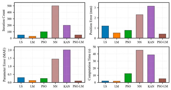
Figure 3.
Comparative performance evaluation of parameter identification algorithms.
In terms of convergence accuracy, the proposed PSO-LM hybrid algorithm demonstrates the most superior performance, achieving an end-effector position error of merely 0.41 mm, which significantly outperforms all other comparative algorithms. Specifically, it exhibits a 21.2% improvement in positioning accuracy over the conventional LM algorithm (0.52 mm) and a 47.4% enhancement over the standard PSO method (0.78 mm). The improvement is even more pronounced when compared to neural network-based approaches such as NN and KAN. Furthermore, the average parameter estimation error is reduced to a notably low level of 0.09, confirming that the identified kinematic parameters are closer to the actual values.
With regard to computational efficiency, the PSO-LM algorithm achieves an exceptional balance between precision and time cost. Although its computation time (5.3 s) is slightly longer than that of the LM algorithm (1.8 s), it achieves a 57.6% reduction in runtime compared to the standalone PSO (12.5 s). Moreover, when compared to neural network-based methods, which require more than 38 s, the proposed method attains an efficiency improvement exceeding 86%, effectively addressing the computational bottleneck that hinders the real-time application of such methods in practical engineering scenarios.
In conclusion, the PSO-LM algorithm is not a mere compromise but a synergistic enhancement: it preserves the fast local convergence of the LM algorithm while effectively mitigating its sensitivity to initial conditions through the global exploration capability of PSO, resulting in comprehensive performance superiority over all standalone algorithms. It is important to emphasize that parameter estimation constitutes the core of the kinematic identification process. While error modeling and data measurement provide the necessary inputs, the ultimate accuracy of kinematic parameter identification is fundamentally determined by the performance of the optimization algorithm when experimental conditions are fixed.
5. Fibonacci Spiral-Driven Optimal Sampling Methodology
The accuracy of manipulator kinematic parameter identification exhibits strong dependence on the spatial distribution characteristics of end-effector sampling poses. Conventional random sampling methods present inherent limitations: (1) incomplete workspace coverage leading to partial parameter identification, and (2) non-uniform point distribution causing numerical instability in computations. To address these issues, this study proposes a systematic optimized sampling strategy.
5.1. Radial Layering Rule
The spacing between adjacent spherical layers should be carefully selected to achieve balanced workspace coverage. An excessively large interval may result in incomplete coverage of the operational volume, while an overly small interval leads to unnecessary computational overhead and point redundancy.
The equidistant layering strategy for the workspace radius
can be expressed by the following unified formula:
where
: radius value of the
-th spherical boundary layer
: maximum/minimum radius of the workspace
: total number of layers
The number of spherical layers
is determined based on the manipulator’s physical dimensions and task precision requirements. For high-precision applications such as precision assembly or surgical robotics, a larger value (e.g., m ≥ 10) is recommended to ensure comprehensive workspace coverage. Conversely, for tasks with limited computational resources and moderate accuracy demands, a reduced number of layers (m = 3∼5) may be adopted.
5.2. Sampling Point Density Allocation
This study proposes an advanced sampling strategy employing a Fibonacci spiral-based distribution with progressive “outer-dense, inner-sparse” allocation, governed by three fundamental principles:
The stratified allocation is implemented through an exponential attenuation model:
where
: total sampling points, subject to N ≥ m(m + 1)/2
: attenuation coefficient governing inter-layer reduction rate
: layer index
: ceiling function
- For a total of m layers, the sampling points at each layer (where k = 1 denotes the outermost layer) adhere to the strictly decreasing relationship , ensuring higher sampling density in outer regions.
- Geometric Attenuation Mechanism: A fixed attenuation coefficient controls the inter-layer sampling reduction ratio, with recommended values of 0.6–0.8. For high-precision applications, is suggested, while is recommended for real-time requirements.
- Dual Boundary Constraints: The outermost layer sampling is bounded by the manipulator’s motion resolution limit, while the innermost layer maintains a minimum sampling threshold (typically ) to ensure parameter identification validity.
5.3. Fibonacci Spiral-Based Optimal Sampling Method
To achieve optimal coverage of sampling points within the manipulator’s workspace, this study employs a deterministic sampling strategy based on the Fibonacci spiral [41], with the spherical coordinate transformation formulated as:
Azimuth angle (
) follows a golden-ratio-based distribution to maximize directional uniformity:
Inclination angle (
) employs an arccosine-based distribution to prevent clustering near the poles:
The 3D coordinates of sampling points
are derived via spherical-to-Cartesian transformation:
The proposed method optimizes the azimuthal angle distribution using the golden ratio principle while employing an arccosine-based distribution for elevation angles, effectively preventing polar clustering and enhancing the representativeness of end-effector sampling positions.
The robotic arm base is fixed to the spacecraft cabin panel (XY-plane), with its operational workspace constrained to the positive Z-hemisphere (Z ≥ 0). Within this hemispherical domain, uniformly distributed Fibonacci spiral points are generated for kinematic parameter identification. As illustrated in Figure 4, the sampling points are visualized in Cartesian space, with distinct markers denoting
different radial layers. A cross symbol at the origin of the base coordinate frame indicates the manipulator’s mounting position.
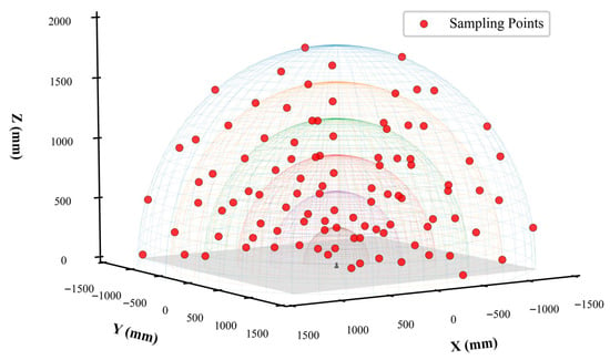
Figure 4.
Kinematic parameter identification robot-arm end position diagram.
6. Experimental Validation
6.1. Experimental Platform Setup
The experiments conducted in this study were performed in a standard laboratory environment. The primary objective is to accomplish a principle verification of the core functionality of the PSO-LM algorithm. The results demonstrate that the proposed algorithm significantly enhances the accuracy of the kinematic model, which robustly validates its strong potential for solving the parameter identification problem. This successful ground-based verification lays a solid foundation for the next logical step: integrating this algorithm as a core module into advanced ground facilities, such as those mentioned by the reviewer, which can emulate microgravity dynamics for closed-loop, system-level testing.
This study proposes a novel kinematic parameter identification method integrating Fibonacci sphere sampling with a PSO-LM hybrid algorithm. To validate its effectiveness under operational conditions, a 6-DOF space manipulator was employed as the test platform, with its DH parameters detailed in Table 1.

Table 1.
DH parameters of the robotic manipulator.
An experimental measurement system was established using a Radian Pro laser tracker (Automated Precision Inc., Rockville, MD, USA), which has a specified accuracy of 0.001 mm and was equipped with a retroreflector target ball to capture the end-effector positions with high precision. The experimental configuration, as illustrated in Figure 5, integrates a 6-DOF robotic manipulator with a laser tracker metrology system.
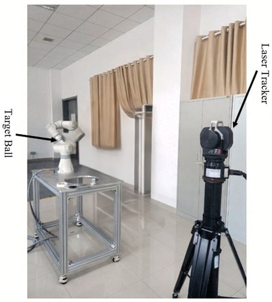
Figure 5.
Experimental setup with manipulator and laser tracker.
To validate the effectiveness of the proposed PSO-LM-based kinematic parameter identification method for space manipulators, a training dataset comprising 45 sets of measured end-effector positions was collected using the robotic arm’s measurement system. Subsequently, 10 randomly selected sets of measured position data were reserved as a validation set to verify the feasibility and generalizability of the identification approach.
6.2. Training Dataset Results
The effective working radius of the manipulator in this study is constrained by multiple factors including joint motion limits, dynamic margins, base structural constraints, and collision avoidance requirements, with a defined operational range of
= 270 mm to
= 850 mm.
Based on the equidistant layering strategy defined in Equation (17), with the given working radius range (
,
), the four-layer division yields the following working layer radii:
= 850 mm,
= 705 mm,
= 560 mm, and
= 415 mm.
Based on the described exponential attenuation model (Equation (18)) with a decay coefficient of
, the 45 sampling points are distributed across four layers (m = 4) as follows:
Layer 1 (Outermost): N1 = 18 points
Layer 2: N2 = 13 points
Layer 3: N3 = 9 points
Layer 4 (Innermost): N4 = 5 points.
The end-effector was controlled to follow a Fibonacci spiral trajectory across predefined calibration points, during which 45 sets of training data were collected.
As illustrated in Figure 6 (where red circles represent desired theoretical positions based on nominal kinematics and blue circles indicate actual end-effector positions measured by the metrology system), the pre-calibration spatial error distribution demonstrated significant dispersion across all axes: X-axis (−15.87 to 11.38 mm), Y-axis (−13.93 to 16.07 mm), and Z-axis (−16.01 to 14.25 mm). Statistical analysis revealed a mean error norm of 11.63 ± 4.12 mm, with the maximum deviation of 18.83 mm occurring at measurement point 5, highlighting substantial positioning inaccuracies prior to kinematic calibration.
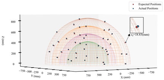
Figure 6.
Spatial distribution of training data points.
The parameter selection for the PSO-LM hybrid algorithm is detailed in Table 2. The particle swarm size was set to 60 (2.5 times the 24-dimensional DH parameter space) based on comprehensive considerations: First, this population size ensures thorough exploration of the high-dimensional parameter space (satisfying the dimensional scaling requirement in Equation (12)) while avoiding ineffective searches caused by excessive particle sparsity in the small dataset of 45 samples. The inertia weight adopts a linear decay strategy from 0.9 to 0.4, designed to enhance global exploration capability through high initial weights (0.9) and accelerate local convergence via low terminal weights (0.4). This dynamic balance effectively coordinates the exploration-exploitation trade-off.

Table 2.
PSO-LM algorithm parameters.
The asymmetric configuration of cognitive coefficient (
= 1.8) and social coefficient (c2 = 1.6) preserves individual particle optimization characteristics (
) while satisfying the stability condition
for swarm intelligence algorithms, preventing premature convergence. The iteration limits of 50 for PSO phase and 20 for LM phase represent a compromise between computational efficiency and convergence accuracy—the former avoids overfitting oscillations with small datasets, while the latter leverages the quadratic convergence property of Jacobian matrices for rapid refinement. The absolute error threshold was set to 0.5 mm to meet the operational requirements of space robotic manipulators.
The identified DH parameters obtained through this optimized PSO-LM calibration process are presented in Table 3, where the kinematic parameters demonstrate notable deviations from their nominal values, particularly in the joint offsets (θ) and link lengths (a), reflecting the compensation for mechanical tolerances and assembly errors in the actual robotic system.

Table 3.
Identified DH parameters.
The calibrated DH parameters were implemented in the manipulator model, and the resulting geometric errors before and after calibration are illustrated in Figure 7. It demonstrates the significant improvement in positioning accuracy achieved through the proposed calibration method, where the red line (BC: Before Calibration) and blue line (AC: After Calibration) represent the error distributions along each axis.
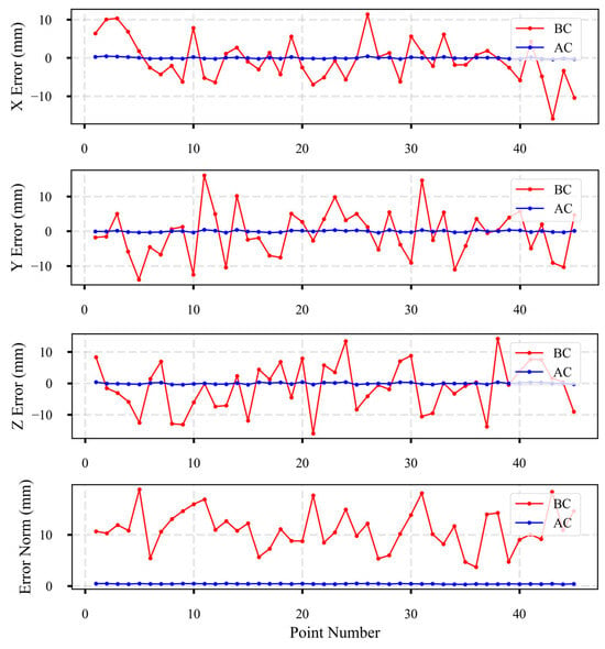
Figure 7.
Position error distribution along different axes.
The implementation of the PSO-LM hybrid calibration algorithm resulted in significant convergence of error distribution, with three-axis error ranges reduced to: X-axis [−0.36, 0.42] mm, Y-axis [−0.45, 0.42] mm, and Z-axis [−0.41, 0.42] mm. Quantitative analysis demonstrated that the mean error norm was reduced to 0.41 ± 0.05 mm (mean ± standard deviation), while the maximum error norm of 0.48 mm strictly satisfied the submillimeter accuracy requirement (<0.5 mm). Comparative evaluation of key performance metrics revealed substantial improvements: the mean absolute error (MAE) decreased from 11.63 mm pre-calibration to 0.41 mm post-calibration (96.4% improvement), the error standard deviation was reduced from 4.12 mm to 0.05 mm (98.7% reduction in dispersion), and the maximum error declined from 18.83 mm to 0.48 mm (97.4% reduction). These findings conclusively validate the efficacy of the PSO-LM algorithm in mitigating systematic geometric errors, while indicating that residual errors are predominantly attributable to random noise inherent in the measurement system.
6.3. Validation with Independent Dataset
The validation results from 10 randomly selected test points further confirm the effectiveness of the PSO-LM-based DH parameter calibration, as illustrated in Figure 8. The red and blue lines represent the error distributions before calibration (BC) and after calibration (AC), respectively.
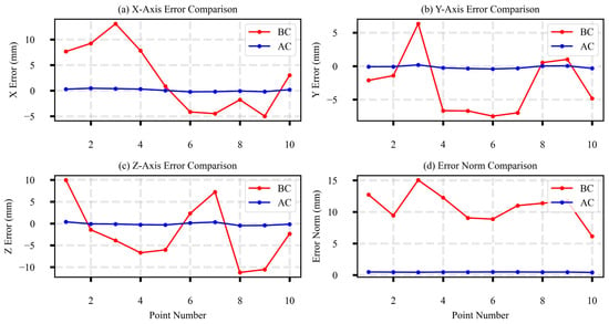
Figure 8.
Comparative error analysis before and after calibration.
Prior to kinematic calibration, significant positioning discrepancies were observed across the entire workspace. The Cartesian errors measured along the X-axis ranged from −4.98 mm to 13.07 mm, along the Y-axis from −7.48 mm to 6.35 mm, and along the Z-axis from −11.22 mm to 9.96 mm. The mean positioning error, expressed in Euclidean norm, was 10.87 mm with a standard deviation of 2.89 mm, reaching a maximum value of 15.04 mm.
Following the implementation of the proposed calibration procedure, a substantial improvement in positioning accuracy was achieved. The mean error norm was reduced to 0.47 mm with a standard deviation of 0.03 mm, while the maximum observed error did not exceed 0.49 mm. Quantitative evaluation demonstrated a 95.7% reduction in mean absolute error (from 10.87 mm to 0.47 mm) and a 98.0% decrease in error variability (standard deviation reduced from 2.89 mm to 0.03 mm). Furthermore, validation experiments conducted at 10 distinct workspace positions confirmed that all absolute errors remained below 0.5 mm while maintaining over 95% compliance in relative error reduction. These results consistently validate the efficacy of the hybrid PSO-LM algorithm in enhancing the positioning accuracy of the robotic manipulator across its operational workspace.
7. Conclusions
This study proposes a hybrid PSO-LM optimization algorithm for high-precision kinematic parameter identification of space manipulators. The proposed methodology provides an effective solution to the critical issue of on-orbit positioning accuracy degradation, offering significant value for future high-precision space missions. The method integrates the global exploration capability of PSO with the local refinement ability of the LM algorithm, effectively overcoming limitations of traditional calibration techniques that often converge to local optima or exhibit strong dependence on initial parameter estimates.
Experimental results demonstrate that the proposed approach significantly enhances calibration accuracy and robustness: the average positioning error is reduced from 10.87 mm to 0.47 mm, representing a 95.7% improvement in relative accuracy. Compared to individual algorithms, PSO-LM achieves a 21.2% increase in positioning accuracy over LM and a 47.4% improvement over standard PSO, while reducing computational time by 57.6%, demonstrating superior overall performance.
The main contributions include (1) a systematic kinematic calibration framework incorporating optimal pose selection through Fibonacci spiral sampling; (2) a novel hybrid optimization mechanism combining stochastic and gradient-based strategies to enhance global convergence and local search efficiency; and (3) experimental validation using a high-precision laser tracker measurement system, confirming the method’s engineering applicability.
While this study has validated the core algorithmic approach for kinematic parameter identification through ground-based experiments on a standard 6-DoF manipulator, several limitations and space-specific challenges require further investigation for on-orbit application. A key limitation is the sensitivity of the identification process to kinematic singularities, where an ill-conditioned Jacobian matrix deteriorates parameter observability. Furthermore, the application to redundant manipulators (e.g., 7-DoF) presents additional challenges in parameter identifiability due to the null-space of the Jacobian. To address these and transition the methodology from ground validation to operational on-orbit applications, future work will focus on (1) integrating a singularity-avoidance criterion (e.g., by maximizing the manipulability measure) into the Fibonacci sampling strategy and exploring constrained optimization frameworks to ensure full parameter observability in redundant systems; (2) compressing the computational footprint of the algorithm to adapt to the limited resources of spaceborne embedded systems; (3) investigating online calibration strategies that can autonomously trigger in response to long-term parameter drift induced by orbital thermal cycling; (4) exploring the coupling effects between kinematic and dynamic parameters in microgravity environments to further enhance the fidelity of the identification model.
Author Contributions
Conceptualization, H.J. and X.M.; methodology, H.J.; software, H.J.; validation, X.M., M.C., J.T., H.X. and J.C.; formal analysis, H.J.; investigation, H.J.; resources, H.J.; data curation, H.J.; writing—original draft preparation, H.J.; writing—review and editing, H.J.; visualization, H.J.; supervision, J.C.; project administration, M.C. All authors have read and agreed to the published version of the manuscript.
Funding
This research received no external funding.
Data Availability Statement
Not applicable.
Conflicts of Interest
The authors declare no conflict of interest.
References
- Madonna, D.P.; Pontani, M.; Gasbarri, P. Berthing proximity maneuvers and trajectory planning of a space manipulator via Kane’s formulation. Acta Astronaut. 2024, 222, 674–691. [Google Scholar] [CrossRef]
- Christidi-Loumpasefski, O.-O.; Papadopoulos, E. On the parameter identification of free-flying space manipulator systems. Robot. Auton. Syst. 2023, 160, 104310. [Google Scholar] [CrossRef]
- Abbott, J.J. Roboticists are grappling with space debris. Sci. Robot. 2025, 10, eadt5685. [Google Scholar] [CrossRef] [PubMed]
- Dreus, A.; Yemets, V.; Dron, M.; Yemets, M.; Golubek, A. A simulation of the thermal environment of a plastic body of a new type of launch vehicle at the atmospheric phase of the trajectory. Aircr. Eng. Aerosp. Technol. 2021, 94, 505–514. [Google Scholar] [CrossRef]
- Li, Y.K.; Li, D.Y.; Zhu, W.S.; Sun, J.; Zhang, X.L.; Li, S. Constrained Motion Planning of 7-DOF Space Manipulator via Deep Reinforcement Learning Combined with Artificial Potential Field. Aerospace 2022, 9, 163. [Google Scholar] [CrossRef]
- Chu, Z.Y.; Ma, Y.; Hou, Y.Y.; Wang, F.W. Inertial parameter identification using contact force information for an unknown object captured by a space manipulator. Acta Astronaut. 2017, 131, 69–82. [Google Scholar] [CrossRef]
- Ma, B.Y.; Jiang, Z.N.; Liu, Y.; Xie, Z.W. Advances in Space Robots for On-Orbit Servicing: A Comprehensive Review. Adv. Intell. Syst-Ger. 2023, 5, 2200397. [Google Scholar] [CrossRef]
- Mao, C.; Chen, Z.; Li, S.; Zhang, X. Separable Nonlinear Least Squares Algorithm for Robust Kinematic Calibration of Serial Robots. J. Intell. Robot. Syst. 2020, 101, 2. [Google Scholar] [CrossRef]
- Vijayan, R.; De Stefano, M.; Dietrich, A.; Ott, C. Unified Control of an Orbital Manipulator for the Approach and Grasping of a Free-Floating Satellite. In IEEE/ASME Transactions on Mechatronics; IEEE: New York, NY, USA, 2025. [Google Scholar] [CrossRef]
- Liu, X.; Behjat, A.; Dyke, S.J.; Whitaker, D.; Ramirez, J.; Bilionis, I. Computational Framework for Assessing Mission Outcomes with Humans and Robots. AIAA J. 2025, 63, 1596–1614. [Google Scholar] [CrossRef]
- Jiuxing, Z.; Wei, Z.; Xuzhi, L.; Zhaojun, J. Research progress of on-orbit servicing technology on space astronomy. In Proceedings of the International Astronautical Congress; IAC: Gifu, Japan, 2018. [Google Scholar]
- Flores-Abad, A.; Ma, O.; Pham, K.; Ulrich, S. A review of space robotics technologies for on-orbit servicing. Prog. Aerosp. Sci. 2014, 68, 1–26. [Google Scholar] [CrossRef]
- Xu, W.F.; She, Y.; Xu, Y.S. Analytical and semi-analytical inverse kinematics of SSRMS-type manipulators with single joint locked failure. Acta Astronaut. 2014, 105, 201–217. [Google Scholar] [CrossRef]
- Thiele, T.; Gülhan, A.; Olivier, H. Instrumentation and Aerothermal Postflight Analysis of the Rocket Technology Flight Experiment ROTEX-T. J. Spacecr. Rocket. 2018, 55, 1050–1073. [Google Scholar] [CrossRef]
- Bechini, M.; Quadrelli, M.B.; Lavagna, M.; Wang, J.J. Hovering of an Electrically Actuated Spacecraft in a Small-Body Plasma Field. J. Spacecr. Rocket. 2021, 58, 1461–1476. [Google Scholar] [CrossRef]
- Shen, M.; Huang, X.; Zhao, Y.; Wang, Y.; Li, H.; Jiang, Z. Human-like acceleration and deceleration control of a robot astronaut floating in a space station. ISA Trans. 2024, 148, 397–411. [Google Scholar] [CrossRef]
- Jiang, Y.; Xu, X.; Zhang, L.; Zou, T. Model free predictive path tracking control of variable-configuration unmanned ground vehicle. ISA Trans. 2022, 129, 485–494. [Google Scholar] [CrossRef]
- Wu, J.; Wang, J.S.; You, Z. An overview of dynamic parameter identification of robots. Robot. C-Int. Manuf. 2010, 26, 414–419. [Google Scholar] [CrossRef]
- Karan, B.; Vukobratovic, M. Calibration and Accuracy of Manipulation Robot Models—An Overview. Mech. Mach. Theory 1994, 29, 479–500. [Google Scholar] [CrossRef]
- Gang, C.; Tong, L.; Ming, C.; Xuan, J.Q.; Xu, S.H. Review on Kinematics Calibration Technology of Serial Robots. Int. J. Precis. Eng. Man. 2014, 15, 1759–1774. [Google Scholar] [CrossRef]
- Yu, B.; Lee, J.; Park, S.H.; Kim, M. From Unified Robot Description Format to DH Parameters: Examinations of Two Different Approaches for Manipulator. IEEE Access 2024, 12, 133441–133455. [Google Scholar] [CrossRef]
- Mueller, A. Modern Robotics: Mechanics, Planning, and Control [Bookshelf]. IEEE Control Syst. Mag. 2019, 39, 100–102. [Google Scholar] [CrossRef]
- Wang, J.D.; Yang, C.H.; Wu, Z.Y.; Wang, Q.J.; Tang, L.Y.; Li, A. Method for robot kinematic parameters identification based on position and orientation data obtained with laser tracker. Rev. Sci. Instrum. 2024, 95, 105105. [Google Scholar] [CrossRef] [PubMed]
- Zhao, W.Z.; Wang, Y.N.; Zhang, J.W.; Liu, Y.H. Parameter Identification and Scanning Pose Optimization for Robotic Vision Measurement System. IEEE-Asme T. Mech. 2025, 30, 541–553. [Google Scholar] [CrossRef]
- Dzubba, M.; Neubauer, M.; Hinze, C.; Lechler, A.; Verl, A. A Nonlinear Elasticity Model and Feedforward Compensation Method to Increase Positioning Accuracy of Industrial Robots. IEEE Trans. Autom. Sci. Eng. 2025, 22, 16168–16184. [Google Scholar] [CrossRef]
- Antonelli, G.; Chiaverini, S.; Fusco, G. A calibration method for odometry of mobile robots based on the least-squares technique: Theory and experimental validation. IEEE T. Robot. 2005, 21, 994–1004. [Google Scholar] [CrossRef]
- Qiao, G.; Jiang, X.; Zhang, M.; Gao, C.; Zhang, Y. A continuous kinematic calibration method for accuracy maintenance of industrial robot based on recursive least squares algorithm. Sci. Rep. 2025, 15, 11397. [Google Scholar] [CrossRef]
- Zhang, T.; Zhang, B.; Sun, Z. A Method of Robot DH Parameter Calibration Based on the Genetic Algorithm. In Proceedings of the 2024 8th International Conference on Robotics and Automation Sciences (ICRAS), Tokyo, Japan, 21–23 June 2024; pp. 1–5. [Google Scholar]
- Yan, J.W.; Pan, B.; Fu, Y.L. Ultrasound-guided prostate percutaneous intervention robot system and calibration by informative particle swarm optimization. Front. Mech. Eng. 2022, 17, 3. [Google Scholar] [CrossRef]
- Yu, D.Y. Kinematic Parameter Identification for a Parallel Robot with an Improved Particle Swarm Optimization Algorithm. Appl. Sci. 2024, 14, 6557. [Google Scholar] [CrossRef]
- Deng, X.; Ge, L.; Li, R.; Liu, Z.; IEEE. Research on the kinematic parameter calibration method of industrial robot based on LM and PF algorithm. In Proceedings of the 32nd Chinese Control And Decision Conference (CCDC), Hefei, China, 22–24 August 2020; pp. 2198–2203. [Google Scholar]
- Shuai, H.; Li, F. Physics-Informed Kolmogorov-Arnold Networks for Power System Dynamics. IEEE Open Access J. Power Energy 2025, 12, 46–58. [Google Scholar] [CrossRef]
- Peng, J.; Zhao, X.; Ma, J.; Meng, D.; Jia, S.H.; Zhang, K.; Gu, C.Y.; Ding, W.H. State of Health Estimation of Li-Ion Battery via Incremental Capacity Analysis and Internal Resistance Identification Based on Kolmogorov-Arnold Networks. Batteries 2024, 10, 315. [Google Scholar] [CrossRef]
- Kang, R.J.; Chanal, H.; Dai, J.S.; Ray, P. Comparison of numerical and neural network methods for the kinematic modeling of a hybrid structure robot. Proc. Inst. Mech. Eng. C J. Mech. 2015, 229, 1162–1171. [Google Scholar] [CrossRef]
- Huber, N.; Tsakmakis, C. A neural network tool for identifying the material parameters of a finite deformation viscoplasticity model with static recovery. Comput. Method. Appl. M. 2001, 191, 353–384. [Google Scholar] [CrossRef]
- Olivares-Mendez, M.; Makhdoomi, M.R.; Yalçin, B.C.; Bokal, Z.; Muralidharan, V.; Del Castillo, M.O.; Gaudilliere, V.; Pauly, L.; Borgue, O.; Alandihallaj, M.; et al. Zero-G Lab: A multi-purpose facility for emulating space operations. J. Space Saf. Eng. 2023, 10, 509–521. [Google Scholar] [CrossRef]
- Tian, W.; Mei, D.Q.; Li, P.C.; Zeng, Y.F.; Hong, P.; Zhou, W. Determination of optimal samples for robot calibration based on error similarity. Chin. J. Aeronaut. 2015, 28, 946–953. [Google Scholar] [CrossRef]
- Miao, L.; Zhang, Y.L.; Song, Z.C.; Guo, Y.J.; Zhu, W.D.; Ke, Y.L. A two-step method for kinematic parameters calibration based on complete pose measurement-Verification on a heavy-duty robot. Robot. C-Int. Manuf. 2023, 83, 102550. [Google Scholar] [CrossRef]
- Delgarm, N.; Sajadi, B.; Kowsary, F.; Delgarm, S. Multi-objective optimization of the building energy performance: A simulation-based approach by means of particle swarm optimization (PSO). Appl. Energy 2016, 170, 293–303. [Google Scholar] [CrossRef]
- Budil, D.E.; Lee, S.; Saxena, S.; Freed, J.H. Nonlinear-Least-Squares Analysis of Slow-Motion EPR Spectra in One and Two Dimensions Using a Modified Levenberg–Marquardt Algorithm. J. Magn. Reson. Ser. A 1996, 120, 155–189. [Google Scholar] [CrossRef]
- Falcón, S.; Plaza, Á. On the 3-dimensional k-Fibonacci spirals. Chaos Solitons Fractals 2008, 38, 993–1003. [Google Scholar] [CrossRef]
Disclaimer/Publisher’s Note: The statements, opinions and data contained in all publications are solely those of the individual author(s) and contributor(s) and not of MDPI and/or the editor(s). MDPI and/or the editor(s) disclaim responsibility for any injury to people or property resulting from any ideas, methods, instructions or products referred to in the content. |
© 2025 by the authors. Licensee MDPI, Basel, Switzerland. This article is an open access article distributed under the terms and conditions of the Creative Commons Attribution (CC BY) license (https://creativecommons.org/licenses/by/4.0/).