Abstract
This paper analyzes the output voltage of an inductive wireless power transfer (WPT) depending on coupling conditions. When the optimum efficiency and maximum output power are obtained, it is called critical coupling, so the receiving coil and the transmitting coil should be separated by a certain distance. When the distance between the transmitting coil and receiving coil is very short, it is called over coupling, and output power decreases with the optimal operating state of the critical coupling condition. To design the entire circuit system for the inductive WPT depending on the coupling condition, it is beneficial to analyze the output voltage according to a load variation, an input voltage, and an operating frequency. Therefore, the output voltage depending on the coupling condition in the inductive WPT is analyzed in this paper. The output voltage gain in critical coupling condition is greater than one and is not affected by a load variation by a series LC resonant operation. The reduced output power in an over coupling condition can be recovered by a series LLC resonant operation. In addition, the output voltage gain is almost one and is affected by the load variation in the over coupling condition. A 5W prototype is implemented with the wireless power consortium standard coils and experimental results are shown to verify theoretical analysis and operation.
1. Introduction
Wireless power transfer (WPT) has been researched for a wireless computing environment. WPT uses magnetic coupling or electric coupling to transfer power wirelessly. A general system is composed of an inverter, matching circuit, rectifier, and transmitting coupling medium such as capacitors or coils, as shown in Figure 1 [1]. In particular, an inductive WPT using magnetic coupling was commercialized for charging mobile devices cordlessly, and the wireless power consortium (WPC) has standardized the inductive WPT for a low power application. Many WPT smartphone chargers have been developed with the WPC standard [2]. The inductive WPT has many good features. The inductive WPT used in the WPC standard is a magnetic resonance WPT with a low-quality factor of transmitting and receiving coils. Operation frequency is determined by a resonance between a coil and a lumped capacitor. Since the operation principle of the WPC method is the same as the magnetic resonance WPT, the output power can be obtained in the highest level of coupling without frequency splitting via a critical coupling and output power decreases in very close clearance, via over coupling, between a transmitting coil and a receiving coil [3]. The WPC standard recommends that the distance between two coils be more than 2 mm [4].
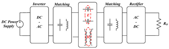
Figure 1.
Simple structure of wireless power transfer system with magnetic and electric [1] coupling [1].
The prior research has focused on the analysis of the maximum power point of the system [5,6,7]. The maximum power point in a two-coil structure is inconsistent with the maximum efficiency point [5,6]. The frequency splitting problem of two coils and three coils was studied, and the influence of frequency splitting on the output power was analyzed [7]. In the conventional WPT system, it has been shown that maximum power transfer is possible only by making the resonance frequency and the operating frequency the same [8,9,10]. Some studies have found that output power is maximized in the critical coupling condition [11,12]. Other works have studied maximizing system efficiency [13,14]. It is possible to minimize the loss and maximize the coupling coefficient by designing a magnetic coupling system with high-quality factor [13]. Another way to gain high efficiency is to reduce proximity effect losses by increasing the separation between coil turns or increasing the number of the turns within the given area [14]. The other studies have increased the transferring distance or improved efficiency by increasing the number of coils [15,16]. However, in the inductive WPT system, the coupling condition is changed according to the position of the receiver. It is needed to analyze an output voltage and a circuit operation according to a load condition, an input voltage, and an operating frequency to design the entire circuit system for the inductive WPT depending on the coupling condition. In particular, for low-power wireless charging systems for mobile devices like the WPC standard, the output voltage characteristics help to design the WPT system when the distance between the transmitting and receiving coils can be very close, or more than 2 mm, as recommended by the WPC. The prior studies lacked the output voltage characteristics for the load variation, the input voltage, and the operating frequency depending on the coupling condition.
Therefore, the output voltage analysis of an inductive WPT using the WPC coils with LC and LLC resonance operations according to the distance between transmitter and receiver coils is studied in this paper. According to the coupling condition with the commercialized WPC coils, the optimal frequency and operation method are considered to obtain the sufficient output power and the voltage in desired applications depending on the coupling condition. When the distance from the transmitter to the receiver is more than 2 mm via a critical coupling condition, the output power and voltage can be obtained by a series LC resonance operation. The output voltage in the critical coupling condition is greater than one and is not affected by a load variation. In addition, when the distance from the transmitter to the receiver is within 2 mm via an over coupling condition, a series LLC resonant operation is suitable to recover output power with high efficiency. When there is the over coupling condition, the coils can be modeled with a magnetized inductor, a leakage inductor, and an ideal transformer and the series LLC resonance operation can be obtained [17]. The output voltage gain is about one and is affected by the load change in the over coupling condition. The series LLC resonant operation obtains higher efficiency in the over coupling condition than in the critical coupling due to low switching loss of semiconductor devices in MOSFEs and diodes. Operation and features are verified with a 5W prototype using WPC standard coils.
2. LC resonance Operation in Critical Coupling
When the distance is about 2 mm in the inductive WPT of the WPC standard, it is a critical coupling condition and the operation uses resonance between the transmitter and receiver coils. The circuit system is shown in Figure 2. The WPC standard recommends that operational frequency be about 120 kHz. This chapter analyzes simple circuit system operation and output voltage characteristics under the critical coupling condition.
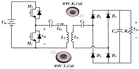
Figure 2.
Wireless power consortium (WPC) LC series resonant circuit in the critical coupling condition.
2.1. LC resonance Operation
Figure 3 shows operational waveforms of the LC resonance operation. By turning on and turning off M1 and M2 switches, rectangular voltage is enforced to the transmitter LC resonator and power can transfer from transmitter to receiver. Zero voltage switching (ZVS) of MOSFETs and zero current switching (ZCS) of rectifiers cannot be achieved. The operation of the circuit is simple.
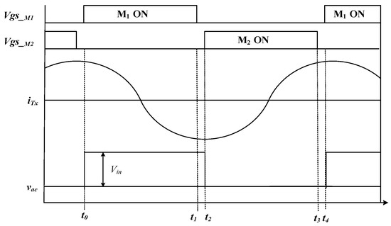
Figure 3.
Simple operational waveform in the LC resonance operation.
2.2. DC Voltage Gain in the LC Resonance Operation
Figure 4 shows the equivalent circuit model of an LC resonance operation. VinF and VoF are the first harmonic of the Fourier series expansion of the input and output square voltages, respectively. Kirchhoff’s voltage law (KVL) equations for the LC resonance operation are given by
where M is mutual inductance, Rac is an equivalent AC resistor, Ro is a load resistor, Resr is some parasitic resistor in the transmitter, and k is a coupling coefficient. The output voltage can be determined by Rac and switching frequency given the coupling coefficient as shown in Equation (5). When the resonant frequency and switching frequency are the same, an output voltage gain is greater than one and the output voltage is not affected by the load variation as shown in Figure 5. Therefore, the WPC standard recommends that operation frequency be determined by
where fs is switching frequency. This can make it possible to determine an input voltage, an operating frequency, kinds of parts etc. for a low-power WPT system at the critical coupling condition.
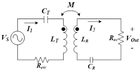
Figure 4.
Equivalent circuit model in LC resonance operation.
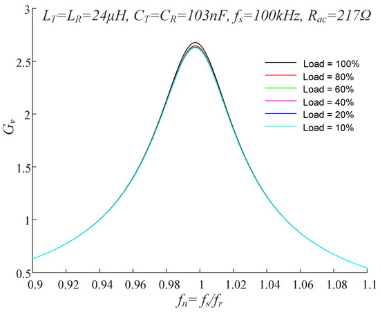
Figure 5.
Voltage conversion ratio according to load variation.
3. LLC Resonance Operation in Over Coupling
The operation method is changed to obtain the same output power in the critical coupling condition when the distance is less than about 2 mm. When the distance between the WPC transmitter and receiver coils is within 2 mm, a coupling coefficient is greater than that of critical coupling, and this state is called an over coupling condition. In this condition, a series LLC resonant operation with the WPC coils can be obtained with a leakage inductance, a magnetized inductor and the external capacitor for an inductive WPT system as shown in Figure 6. Transmitter and receiver inductors can be modeled with a magnetized inductor, a leakage inductor and an ideal transformer.
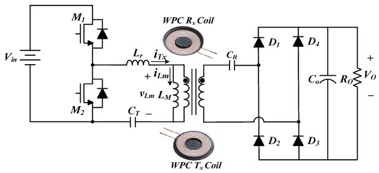
Figure 6.
Equivalent LLC resonant resonance circuit in the over coupling condition.
3.1. LLC Resonance Operation
As shown in Figure 6, the WPC WPT coils can be regarded as a transformer and an inductive WPT system can be driven by a series LLC resonance operation. The operation of the proposed circuit is similar to that of the conventional LLC resonance DC/DC converter [17]. The proposed circuit has four modes in operation, as shown in Figure 7. The operation from modes 1 to 2 is shown.
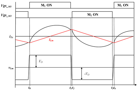
Figure 7.
Operational waveform in LLC resonance operation.
Mode 1(t0~t1): Mode 1 begins by turning on the M1 switch. Before the switch is turned on, the output capacitor of the M1 is discharged and achieves the ZVS of MOSFETs by the magnetized inductor LM. By the resonance between the Lr and the coupling capacitors, CT and CR, the current of Lr is increased, D1 and D3 are turned on, and the power is transferred to the load. The voltage across LM is the output voltage.
Mode 2(t1~t2): When the resonance between the Lr and the coupling capacitors is finished, mode 2 begins. The D1 and D3 are turned off in the ZCS and switch M1 is turned off. The voltage of the output capacitors in M1 and M2 are discharged and charged by the resonance with the inductors. When the voltage of Lp is −Vo, mode 2 finishes.
3.2. DC Voltage Gain in the LLC Resonance Operation
Figure 8 shows a transformer model for the WPC transmitter and receiver coils. This transformer model can be useful in the over coupling condition. Inductance of L1 and L2 is larger than that of LT and LR because ferrite sheets in transmitter and receiver coils influence the over coupling condition. Lr and LM inductor can be given by
where k is the coupling coefficient, NT is the number of turns in the transmitter coil, NR the number of turns in the receiver coil, Mover is mutual inductance, and LSC1 is an inductance when the receiver inductor is short.
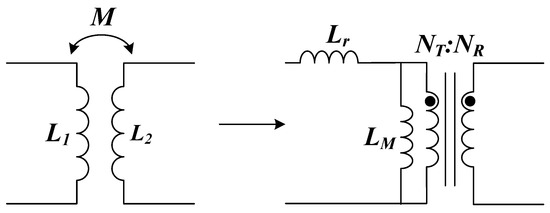
Figure 8.
Equivalent transformer model for the WPC coils.
Figure 9 shows the equivalent circuit model of an LLC resonance operating. VinF and VoF are the first harmonic of the Fourier series expansion of the input and output square voltages, as shown in the prior section. When NT and NR are the same, an output voltage gain in the over coupling condition can be given by
where Cr is . The output voltage gain in the over coupling condition is similar to that of the conventional LLC resonant DC/DC converter, as shown in Figure 10 [17]. Therefore, the switching frequency can be determined by
where fs is switching frequency. If the operating frequency is set as in Equation (14), a constant output voltage can be obtained regardless of the load variation. However, the fo changes due to the deviation of the coil inductance and resonant capacitance. If the fn is operated less than 1, the output voltage gain is affected by the load variation, and at the maximum load, the output voltage gain becomes smaller than one. When the load decreases, the output voltage gain increases. These can make it possible to design an input voltage, an operating frequency, devices etc. for a low power inductive WPT system at the over coupling condition.
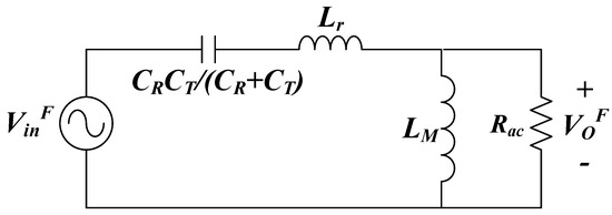
Figure 9.
Equivalent circuit model in LLC resonance operation.
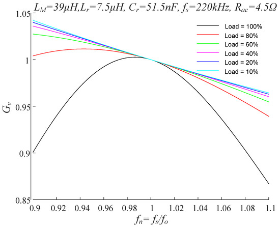
Figure 10.
Equivalent circuit model in LC resonance operation.
4. Experiment Results
An experimental prototype for a commercialized WPC 5W charger for a mobile device was implemented to verify the proposed operation, as shown in Figure 11. Table 1 shows the parameters in series LC and LLC resonance operations. As shown in Figure 12, the maximum output power is 5W with a distance of more than 2 mm between two coils, the operation is the series LC resonance and the switching frequency is about 120 kHz.
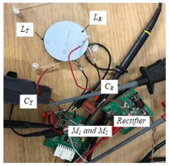
Figure 11.
Experimental set.

Table 1.
Specific Components of the prototype.
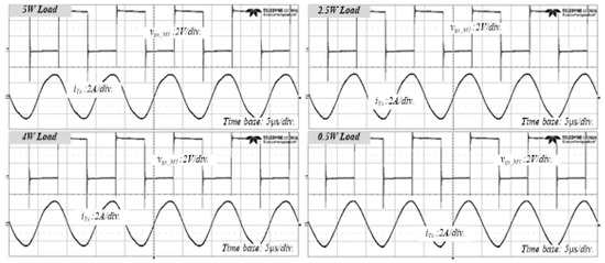
Figure 12.
Experimental waveforms in the critical coupling condition.
Figure 13a shows that the output voltage is higher than input voltage and is constant regardless of load variation, as in the theoretical analysis. Efficiency is below 70% at a full load condition and decreases at a light load condition, as shown in Figure 13b, because the current in the transmitter is almost same when the load is small, as shown in Figure 12.
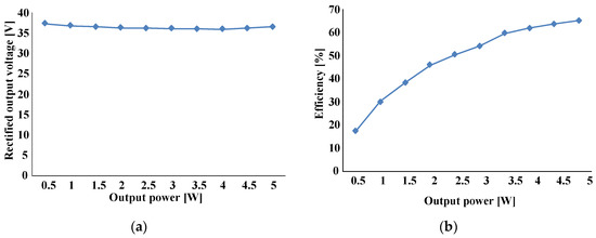
Figure 13.
Output voltage and efficiency according to load variation: (a) output voltage; (b) efficiency.
However, the same output power cannot be obtained with the series LC resonance operation in 2 mm distance between two coils, as shown in Figure 14. When the distance between the transmitter and receiver coils is below 2 mm, the coupling coefficient is about 0.92 by Equation (10), and this is an over coupling condition.
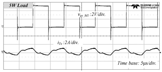
Figure 14.
Experimental waveforms in the over coupling condition with the LC resonance operation.
However, the 5W output power is recovered by the LLC operation with increasing the switching frequency, as shown in Figure 15. As shown in Figure 15, as the theoretical analysis, the output voltage and output power are affected by the load variation in the over coupling condition and the current on the transmitter decreases as the load decreases. Figure 16a shows that the output voltage is almost same with a half of the input voltage in the full load condition. Figure 16b shows that efficiency above 70% at the full load is higher than the critical coupling condition by low switching loss in the MOSFETs and the diodes, even though the frequency has increased. The experimental results demonstrate the validity of the theoretical analysis of the output voltage gain when the same output power is obtained in the series LC and LLC resonant operations depending on the coupling conditions.
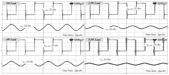
Figure 15.
Experimental waveforms in the over coupling condition with the LLC resonance operation.
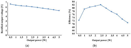
Figure 16.
Output voltage and efficiency according to load variation: (a) output voltage; (b) efficiency.
5. Conclusions
In this paper, an operation method depending on coupling conditions such as the distance between the WPC transmitter and receiver coils is studied. Theoretical output voltage characteristics according to the coupling condition are analyzed, and the validity is verified through experiments with the same output power. A series LC resonance operation is suitable at a distance of more than 2 mm between two coils in the critical coupling condition for an inductive WPT system. A series LLC resonance operation method for the inductive WPT is considered to obtain constant output power in an over coupling condition. The output voltage gain in the critical coupling condition is greater than one and does not change with load variation. The reduced output power in over coupling condition can be recovered by the series LLC resonant operation. In addition, the output voltage gain is almost one and is affected by the load variation in the over coupling condition. The LLC resonance operation can be a good solution to compensate the low efficiency in over coupling inductive WPT. The analyzed results are expected to be useful at coupling conditions in designing a low power inductive WPT system for the wireless charging of a mobile device.
Acknowledgments
This research was supported by the Daegu University Research Grant, 2018.
Conflicts of Interest
The authors declare no conflict of interest.
References
- You, Y.; Yi, K. Capacitive Coupling LLC Wireless Power Transfer Converter through Glasses of Electric Vehicles. Trans. Korean Inst. Power Electron. 2016, 21, 542–545. [Google Scholar] [CrossRef]
- Available online: https://www.wirelesspowerconsortium.com (accessed on 20 February 2020).
- Zhang, Y.; Zhao, Z. Frequency Splitting Analysis of Two-Coil Resonant Wireless Power Transfer. IEEE Antennas Wirel. Propag. Lett. 2014, 13, 400–402. [Google Scholar] [CrossRef]
- Available online: https://www.wirelesspowerconsortium.com/knowledge-base/specifications/download-the-qi-specifications.html (accessed on 20 December 2019).
- Li, Y.; Zhang, Y.X.; Yang, Q.X.; Yan, Z.; Zhang, X.; Xue, M.; Yang, X.B. Analysis and experimental validation on maximum power and efficiency in wireless power transfer system via coupled magnetic resonances. Trans. China Electrotech. Soc. 2016, 31, 18–24. [Google Scholar]
- Li, Y.; Yang, Q.X.; Yan, Z.; Chen, H.Y.; Zhang, X.; Jin, L.; Xue, M. Characteristic of frequency in wireless power transfer system via magnetic resonance coupling. Electr. Mach. Control 2012, 16, 7–11. [Google Scholar]
- Huang, R.; Zhang, B.; Qiu, D.; Zhang, Y. Frequency Splitting Phenomena of Magnetic Resonant Coupling Wireless Power Transfer. IEEE Trans. Magn. 2014, 50, 8600204. [Google Scholar] [CrossRef]
- Zhong, W.X.; Zhang, C.; Liu, X.; Hui, S.R. A methodology for making a three-coil wireless power transfer system more energy efficient than a two-coil counterpart for extended transfer distance. IEEE Trans. Power Electron. 2015, 30, 933–942. [Google Scholar] [CrossRef]
- Ye, Z.; Sun, Y.; Dai, X.; Tang, C.; Wang, Z.; Su, Y. Energy efficiency analysis of U-Coil wireless power transfer system. IEEE Trans. Power Electron. 2016, 31, 4809–4817. [Google Scholar] [CrossRef]
- Zhang, Y.; Lu, T.; Zhao, Z.; He, F.; Chen, K.; Yuan, L. Selective wireless power transfer to multiple loads using receivers of different resonant frequencies. IEEE Trans. Power Electron. 2015, 30, 6001–6005. [Google Scholar] [CrossRef]
- Ahn, D.; Hong, S. A Study on Magnetic Field Repeater in Wireless Power Transfer. IEEE Trans. Ind. Electron. 2012, 60, 360–371. [Google Scholar] [CrossRef]
- Seo, D.-W.; Lee, J.H.; Lee, H.S. Study on Two-Coil and Four-Coil Wireless Power Transfer Systems Using Z-Parameter Approach. ETRI J. 2016, 38, 568–578. [Google Scholar] [CrossRef]
- Manteghi, M. A new resonator for high efficiency wireless power transfer. In Proceedings of the IEEE Propagation Society International Symposium (APSURSI), Orlando, FL, USA, 7–13 July 2013; pp. 838–839. [Google Scholar]
- Sampath, J.P.K.; Alphones, A.; Vilathgamuwa, D.M.; Ong, A.; Nguyen, X.B. Coil enhancements for high efficiency wireless power transfer applications. In Proceedings of the IECON 2014-40th Annual Conference of the IEEE Industrial Electronics Society, Dallas, TX, USA, 29 October–1 November 2014; pp. 2978–2983. [Google Scholar]
- Sum, Y.; Liao, Z.-J.; Ye, Z.-H.; Tang, C.-S.; Wang, P.-Y. Determining the maximum power transfer points for MC-WPT systems with arbitrary number of coils. IEEE Trans. Power Electron. 2018, 33, 9734–9743. [Google Scholar]
- Mastri, F.; Mongiardo, M.; Monti, G.; Tarricone, L.; Constanzo, A. Optimal couplings for a four-coils WPT link. In Proceedings of the 2018 48th European Microwave Conference, Madrid, Spain, 23–27 September 2018; pp. 182–185. [Google Scholar]
- Kim, J.-W.; Park, M.-H.; Lee, B.-H.; Lai, J.-S. Analysis and Design of LLC Converter Considering Output Voltage Regulation Under No-Load Condition. IEEE Trans. Power Electron. 2020, 35, 522–534. [Google Scholar] [CrossRef]


© 2020 by the author. Licensee MDPI, Basel, Switzerland. This article is an open access article distributed under the terms and conditions of the Creative Commons Attribution (CC BY) license (http://creativecommons.org/licenses/by/4.0/).