Abstract
Optimal power sharing between parallel inverters and the demand load in microgrids is challenging and particularly critical for power grids in islanding operation. This paper introduces a novel control approach for managing parallel distributed power sources in the presence of variable load in islanding regime. The proposed scheme is based on the modified sliding mode control (MSMC) which is combined with the optimal Riccati control method to achieve convergence at the slip level with higher accuracy. The mathematical principles of the network equations are derived and its stability is obtained using the Lyapunov function. The MSMC simulation results are discussed in relation to the conventional droop method, while the laboratory evaluation was carried out to characterize its dynamic and static response. The results show that the proposed scheme control is able to manage the distributed power generation for static and dynamic load scenarios, and as such, guarantying microgrid frequency stability.
1. Introduction
Distributed generation (DG) plants are now common in the electricity network, and are mainly related to the increasing exploitation of renewable energy sources (RES). DGs play an important role in pollution reduction, power loss reduction and power quality improvements, which are more important in large scale networks. On the other hand, using DG units can be challenging in some issues such as: reverse power flow, voltage deviation and voltage fluctuation. When many DG units supply a certain load separately adjacent to each other, in fact they form a microgrid (MG) that can solve many challenges in the power network [1]. Figure 1 shows a typical MG architecture adjacent to an AC system, local controllers (LCs) and MG central controller (MGCC). Photovoltaic and energy storage systems (ESS) connect to the AC system by a DC–DC–AC converter. Additionally, wind turbines connect to AC bus bars by an AC–DC–AC converter. In islanding operation mode, in addition to controlling voltage and frequency, RESs are responsible for supplying local loads. The AC bus bar, which is connected to the upstream network in the connected to network mode, is very important and is known as the point of common coupling (PCC) bus. This bus controls power flow and load distribution between MG and the upstream network [2].
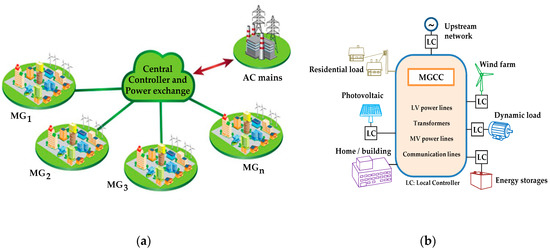
Figure 1.
(a) Power exchange for microgrids (MGs) and the upstream network; (b) the equipment of a typical MG.
MG stability is a critical issue, requiring an appropriate control scheme to face real time power requirements in the presence of constant load changes of varying natures. In this sense, the DG’s capability to provide active and reactive powers is mandatory to limit MG voltage and frequency deviation. Droop controller is one of the well-known controllers in this field which has been used in recent years [3]. Additionally, a novel control method, named virtual synchronous generator (VSG) which functions in accordance with fluctuation equations, is proposed to control network steady state and transient state [4]. Due to the fact that the inertia of DG units has a great impact on the droop controller, VSG output active and reactive powers dynamically distributes among DG units in a way that its virtual inertia and other DGs are retained. Thus, the implementing of an improved droop method for power distribution is still one of the popular algorithms in MG islanding operation among researchers. However, this method faces serious challenges in reactive power distribution. An improved droop method is proposed in [5] to improve dynamic stability in active and reactive power distribution. Additionally, an adaptive distributed droop method is presented in [6] to match the dynamic performance of power system characteristics with the network state, considering its static state. Furthermore, to distribute power under complex loading conditions, a strategy based on a regulation algorithm is proposed in [7]. Additionally, to control inverters, the power management is proposed hierarchically in [8]. Although power distribution is performed and MG dynamic response is studied, its economic evaluation has not been executed yet. In [9], the voltage stability in case of a big disturbance has been studied, and a droop-based Q-f and P-V control method that can operate under uncertain feeder impedance condition has been proposed. An important economic problem observed in hierarchical controllers is that active power measurement criterion should be based on generator costs, and not a linear or proportional relationship based on generator size.
A cost-based non-linear algorithm is offered in [10] and a control plan based on droop and prioritized cost is evaluated in [11]. However, the ability of instantaneous reactive power distribution optimization is visible in neither of the mentioned references. When all DGs operate in the same frequency and steady state, active power can be regulated according to the droop control method. However, under non-linear load and unequal feeder impedance, reactive power is still deprived of proper distribution and power harmonics emerge in it [12]. Under this condition and even a more critical condition, poorly active power distribution could result in reactive power flow among DGs. This will lead into instability of the network [13]. So far, to distribute reactive power, many droop-based methods have been presented that are based on three main categories: the improved primary droop control method [14], improved virtual impedance method [15] and improved hierarchical control methods [16].
There are many studies that have concentrated on the power sharing issue, however, some of the limitations and restrictions are still remained. For example, in the active power sharing method using droop control and its derivatives some drawbacks are observed such as: (1) it is not appropriate for total costs minimizations, (2) it is not suitable for multiple DGs utilization, (3) it is not suitable for complex feeder impedance, and (4) the proportional active power sharing could not be achieved [17]. When networked-based approaches or the decoupling method between the P-V and Q-f curves are chosen to obtain the active power sharing, several disadvantages are come into watch such as: (1) it is not suitable for complex MG, (2) the total cost of generation could not be considered, and (3) the proportional active power sharing is not achieved [18,19]. Considering the nonlinear cost-based droop method, it also has two shortcomings as: (1) it is not suitable for complex feeder impedance, and (2) it is not applicable for complicated MG structures [20].
The difficulties of reactive power sharing using optimized secondary control could be expressed as: (1) the proportional reactive power sharing is difficult to achieve, (2) the communication delays still exist in the low-bandwidth communication (LBC), and (3) the control equations need to be further optimized in the MG with complex loads [21]. The programing algorithms for reactive power sharing are useful, but some complications are still observed, such as the complexity of implementation, data drop problems and time delay considerations [22]. The multi-agent method has recently been introduced in MG control and operation. Using this approach for reactive power sharing has many advantages, however, there might be some weaknesses such as: (1) designing an applicable protocol in agents is difficult, (2) the active and reactive power sharing are poor when data drop exists in the preset algorithm, and (3) the communication delay is in LBC lines may cause some interferences [23].
The abovementioned highlights the main research gaps of the accurate power sharing issue. Table 1 and Table 2 represent a comparison between advantages and disadvantages of power distribution control methods for active and reactive sharing, respectively.

Table 1.
Active power sharing techniques and attributes.
Table 2.
Reactive power sharing techniques and attributes.
In [24] the impact of distributed generation in the distribution networks is considering voltage profile improvement and energy losses minimization is investigated, but the optimal power sharing is not achieved. In [25] the islanding effect on distribution networks and end user loads in presented. Since the load sharing in islanding is analyzed, but there are no effects of feeder impedance. The authors in [26] proposed a method for grid monitoring considering energy storage system control, however, the reactive power sharing accuracy is not sufficient in details. For a fuzzy logic hysteresis control of a single phase inverter, the authors in [27] represent an approach to show the effectiveness of control scheme, and finally, in [28], there is a comprehensive review for grid control methods, which are performed in parallel.
This paper is organized as follows: Section 2 presents the fundamentals of DG control in micro grid type networks. Section 3 describes microgrid basic mathematical modeling. A modified sliding mode control (MSMC) based on nonlinearity uncertainties is proposed in Section 4. Section 5 investigate the simulations results and Section 6 discuss the experimental output. Finally, the conclusion is presented in Section 7.
The main contributions in this paper are:
- A modified enhanced SMC method to get better convergence in sliding surface. This method is easy to implement for laboratory tests rather than the multi-agent systems, programming algorithms and network-based approaches.
- The Lyapunov function combined with the optimal Riccati ensure the proposed MSMC scheme is stable. This results in being sure for guaranteeing the stability of control approach in applicable prototype implementation, because some of abovementioned methods do not have capability to check the system stability. In addition, the constant coefficients used to design the Lyapunov function are few.
2. DG Control Fundamentals
The control scheme for two islanded MGs is represented in Figure 2 to show the blocks placements and control loops. In general, there are three control layers that exist to guarantee the MG stability and safe operation:
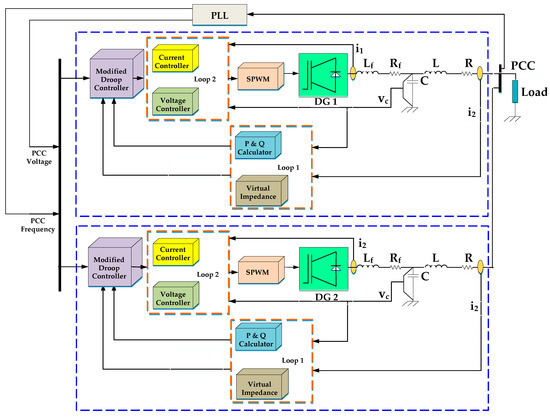
Figure 2.
The control scheme block diagram for two islanded MGs.
- The upper layer (loop 1) controls the voltage and frequency with satisfying precise power balance between loads and the DGs;
- The second layer (loop 2) mitigates the voltage and frequency attenuations, results in reference current vector to make the pulse width modulation (PWM) pulses;
- The third layer usually controls the power exchange with the upstream network in safe operation mode considering the economic power market law.
Figure 3 shows the classic control scheme for the two parallel-DGs in an islanded MG. The MG frequency fMG and measured voltage VMG are compared to the reference signals, respectively to be regulated and attenuation limitation through a proportional-integral-derivative (PID) or proportional-resonance (PR) controller. The regulated signals are transferred to the primary and inner control loop considering a communication lines. The reactive power sharing will be ineffective if the conventional secondary control is applied. These parallel DGs are connected to a common distribution bus with different feeder reactances X1 ≠ X2, as shown in Figure 3, results in unsuccessful voltage maintain [29].
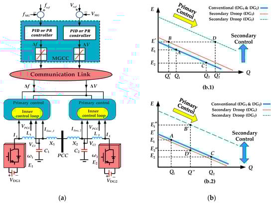
Figure 3.
(a) The classical control scheme for islanded MG; (b) droop control method: one-directional secondary controller effect (b.1) and bi-directional secondary controller effect (b.2) [29,30].
The characteristics of conventional secondary control scheme is shown in Figure 3b. The red and green dashed line is the secondary control curve for DG1 and DG2, respectively, while the blue solid line is the conventional droop control curve. In Figure 3b.1, the points A(Q1,E1) and C(Q2,E2) represent the output voltage of DG1. The injected reactive power Q1 and Q2 result in E1 for DG1 and E2 for DG2, respectively. The points B(Q1′,E*) and D(Q2′,E*) signify the output reactive power of DG1 and DG2 when the voltage is kept constant at the nominal value E* in the conventional secondary control. Conversely, the reactive power deviation between DG1 and DG2 increases as this non-equality Q1′ < Q1 < Q2 < Q2′. Nevertheless, as revealed in Figure 3b.2, once the reactive power is controlled as Q1 = Q2 = Q” in the conventional secondary control, the points B’(Q”,E1”) and D’ (Q”,E2”) will show the output voltages of DG1 and DG2, respectively. However, the voltages of DGs cannot be renovated at the nominal values, so that and the voltage difference is larger than the amount compared to the primary control (E2 < E2“ < E1 < E1“). Therefore, the conventional method may not adjust the output voltages of DGs precisely at equality condition of reactive power [29,30].
3. State Space Power Grid Equations
A control structure for power sharing relying on two parallel DG units is illustrated in Figure 4.
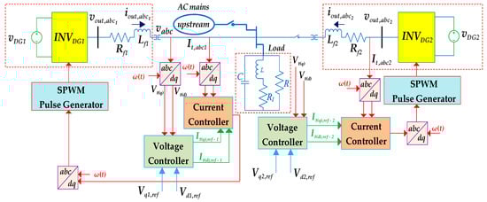
Figure 4.
Two parallel-DG plants equivalent circuit in islanding operation.
For the purpose of studies, the renewable source-based DG plant representation is simplified, as shown below.
The basic equations for the MG system physical description are:
where DG unit output three-phase current, is the voltage at the point of common coupling, is the inductive load current and is the three-phase voltage at inverter output. By applying Clark and Park transformations all variables of each phase mentioned above are translated to a dq rotating frame as follows:
where and are uncertainties related to the inverter. If the state space and input variable are included in state space equations, therefore, we have:
where and are nonlinear functions of state vector and is an indefinite function representing the uncertainties and dynamic attenuations. Assuming that , then it can be found that:
Assume that where and are positive constants. If then the system formulated in (3) will change to:
That the objective function () can minimize the system costs.
where and are nonlinear functions of state vector , which are semi-definite positive and definite positive, respectively. To compensate the uncertainties, the control law is chosen as:
where and are the models of optimized nominal system and uncertainties considering parameter variations and distributions. For the linear systems such as power grid equations around set point, the state-space equations are written as:
The feedback controller using the state-dependent Riccati equation is chosen as follows [31]:
where represents a symmetrical definite positive matrix, which is unique at each set point obtained by solving as:
4. Modified Sliding Mode Control
Considering is a sliding surface which is a function of G(X) and T(t), then the formulation principles are expressed as:
where represents an un-unique matrix, which has to satisfy the non-singularity of . According to (10), it is obvious that the initial state is equal to zero. Consequently, the system is initiated from zero initial condition. Applying first derivative led to:
To satisfy , the control input is obtained as (13).
In order to guarantee the system stability, choosing a Lyapunov function has to meet the negative first derivate criterion. Then, it follows that:
where is a positive constant. To apply the system limitation and to avoid chattering phenomenon, the saturation functions () is used instead of function. System stability evaluation is obtained:
Then:
Using some simplifications lead to:
Applying further simplification, results in:
where is the first order norm of sliding surface. If , it is guaranteed that the first derivate of the Lyapunov function is negative (.
5. Simulation Results
The verification of the proposed technique comprises two simulation scenarios being carried out in MATLAB. The conventional droop controller is compared to the new MSMC strategy regarding active power and reactive power sharing response as well as the system frequency stability. For the sake of clarity, the MG is simulated with four DG power plants having each one a rated apparent power of 8 kVA as shown in Table 3.
Table 3.
Simulated MG electrical specifications.
Figure 5 shows the simulations results using the conventional controller. Initially, the four DG units are delivering a combined active power of 10.8 kW in equal parts though for reactive support a significant imbalance can be seen in Figure 5b. That is to say, the conventional approach cannot handle well the sharing of the reactive power among the four DG units. As it reaches the time instant t = 1.2 s the load active power needs increase by 70%. As observed the active power output is still equally provided and noted that reactive power sharing reacts in the same proportional way. Restoration of voltage and frequency to previous values before the increment of load impedance followed by a decrease of 60 in relation to the original steady state is not possible as clearly seen in Figure 5c,d. In the following scenario the proposed controller is subject to similar working conditions. The controller under study is configured accordingly to the parameters shown in Table 4. Figure 6a,b reveal that in steady state operation, both electrical quantities are generated by showing the proportionality criterion is effectively applied. As for power reactive sharing capability, the non-conventional controller is able to distribute equally the reactive energy output, ensuring DGs output voltage are equal. At the DG plant number 4 is shut down and remains disconnected until the end of the simulation. With loss of one DG unit the remaining DG plants update their response providing almost balanced active power. There is a small mismatch from the DG3 compared to the other two DGs, which are performing equally in terms of power delivery as observed in Figure 6a.
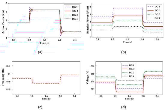
Figure 5.
Scenario with conventional droop controller: (a) active power sharing; (b) reactive power sharing; (c) system frequency; (d) distributed generation (DGs) terminal voltages.
Table 4.
Modified sliding mode control (MSMC) controller parameters.
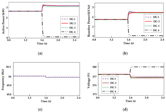
Figure 6.
Scenario with proposed MSMC controller: (a) active power sharing; (b) reactive power sharing; (c) system frequency; (d) DGs terminal voltages.
6. Experimental Verification
Two parallel DG emulating units are part of the three-phase MG prototype to evaluate the new controller under analysis. Figure 7 shows a picture of the equipment used in the laboratorial evaluation. The central controller is operated by a TMS320F28335 DSP from Texas Instruments. Each DG plant consists of six IRF740 MOSFET power devices arranged in a three-phase H-bridge being switched at frequency of 12 kHz. The three-phase output voltage is generated with the SPWM technique. Two types of loads were used in the experiments being both balanced. One consists of resistance and inductance elements with a rated apparent power of 25 VA. The other is basically a three-phase diode bridge connected to a RC load. The complete system specifications are represented in Table 5.
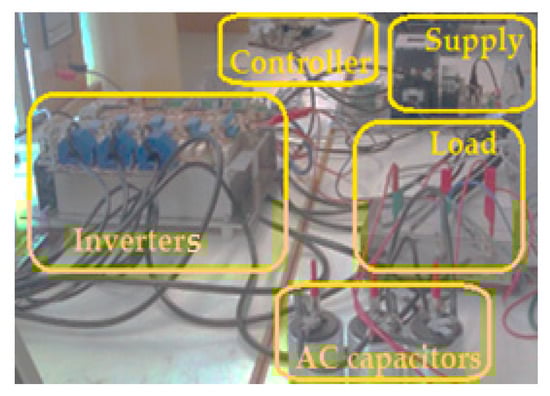
Figure 7.
Simulated MG in laboratory.
Table 5.
Design and system specifications for laboratory tests.
The first practical test was carried out for the linear load having both DGs controlled by the droop technique and some measured quantities are seen in Figure 8. The upper waveforms represent one of the three-phase alternating current at DGs output. As expected, the currents are imbalanced. Compared to the performance in previous Figure 8, MSMC scheme reduces the power sharing errors as revealed by Figure 9.
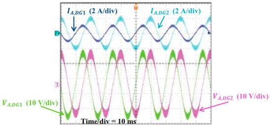
Figure 8.
Experimental results of droop controller: (dark blue trace) DG1 output current, (light blue trace) DG2 output current, (green trace) DG1 output voltage, (pink trace) DG2 output voltage.
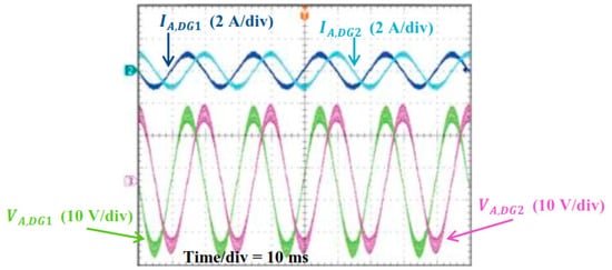
Figure 9.
Experimental results of proposed controller: (dark blue trace) DG1 output current, (light blue trace) DG2 output current, (green trace) DG1 output voltage, (pink trace) DG2 output voltage.
The two-phase currents in each of the DG outputs, respectively, are in good agreement with regard to the measured Ip-p quantities. In the following scenario the RL load is replaced by a three-phase diode rectifier. Figure 10 documents how MSCM performance under such PCC load. It is clear that the high harmonic content current is not an obstacle to deteriorate the power sharing functionality of the proposed control scheme. Therefore, both DG currents have similar profile and amplitude. Naturally, it is observed some voltage waveform degradation which can be fixed with appropriate filtering to meet international standards.
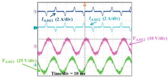
Figure 10.
Experimental results of proposed controller for nonlinear load: (dark blue trace) DG1 output current, (light blue trace) DG2 output current, (green trace) DG1 output voltage, (pink trace) DG2 output voltage.
7. Discussion
The dynamic performance of the conventional control method is compared to MSMC based on the two case studies discussed above, taking into account three quantities (rise time, overshoot and settling time). The measurements are documented in Table 5 and Table 6. In conventional design control, the measured overshoot is limited to 2.12% in the first case study. As for the MSMC, the overshoot is lower, that is 0.78%. The comparison between performance evaluation of these methods for both active and reactive power is represented in Table 6 and Table 7, respectively. Furthermore, the settling time and the rise time have being investigated, with results showing the superiority of the MSMC approach. The root-locus diagram shown in Figure 11 represents the optimum design of proposed control system, while the roots are enough far from the imaginary axis.
Table 6.
Dynamic response performance comparison regarding active power support.
Table 7.
Dynamic response performance comparison regarding reactive power support.
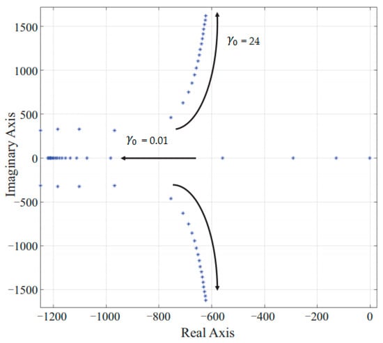
Figure 11.
The root-locus diagram of control system poles.
8. Conclusions
In this paper, a new control method (MSMC) based on a sliding mode technique, aiming at effective power sharing in MG type networks is presented. The proposed scheme takes into account the sliding surface properties by minimizing the constants and defining the zero condition in all initial states, which results in fast convergence and thus guaranteeing network stability. The simulations and tests in the laboratory have shown the feasibility of the technique for power sharing service allowing equal support of active and reactive power needs, whether in steady state load conditions or under dynamic load changes. It was verified that after load changes the network frequency deviation is residual and thus not affecting MG frequency stability. In particular, for load changes events the MSMC scheme dynamic response is very satisfactory with lower overshoot and shorter settling time compared to conventional droop control. As for the MG voltage stability, the voltage drop at the DG terminals are eliminated, proving the reactive power sharing capability is adequate. However, the only drawback of the proposed scheme is the time delay consideration in LBC lines, which could be solved by using a delay block compensation, which will be the subject of study for the authors future works.
Author Contributions
Conceptualization and methodology, E.B.; software H.K.; validation, J.E.; investigation and analysis, M.M.; visualization and supervision, E.P.; investigation, review and editing, E.M.G.R. All authors have read and agreed to the published version of the manuscript.
Funding
This research received no external funding.
Conflicts of Interest
The authors declare no conflict of interest.
References
- Maanavi, M.; Najafi, A.; Godina, R.; Mahmoudian, M.; Rodrigues, E.M.G. Energy Management of Virtual Power Plant Considering Distributed Generation Sizing and Pricing. Appl. Sci. 2019, 9, 2817. [Google Scholar] [CrossRef]
- Jafari, M.; Naderi, S.B.; Hagh, M.T.; Abapour, M.; Hosseini, S.H. Voltage Sag Compensation of Point of Common Coupling (PCC) Using Fault Current Limiter. IEEE Transactions on Power Delivery 2011, 26, 2638–2646. [Google Scholar] [CrossRef]
- Simiyu, P.; Xin, A.; Wang, K.; Adwek, G.; Salman, S. Multiterminal Medium Voltage DC Distribution Network Hierarchical Control. Electronics 2020, 9, 506. [Google Scholar] [CrossRef]
- Yan, X.; Rasool, A.; Abbas, F.; Rasool, H.; Guo, H. Analysis and optimization of the coordinated multi-vsg sources. Electronics 2019, 8, 28. [Google Scholar] [CrossRef]
- Zhang, Y.; Zhang, F.; Quan, Y.; Zhang, P. Analysis of Three-Phase Inverter Parallel Operation with Network-Based Control Having Strong Robustness and Wide Time-Scale Compatibility in Droop-Controlled AC Microgrid. Electronics 2020, 9, 376. [Google Scholar] [CrossRef]
- Hazari, M.; Jahan, E.; Mannan, M.A.; Tamura, J. Coordinated Control Scheme of Battery Storage System to Augment LVRT Capability of SCIG-Based Wind Turbines and Frequency Regulation of Hybrid Power System. Electronics 2020, 9, 239. [Google Scholar] [CrossRef]
- González-Romera, E.; Romero-Cadaval, E.; Roncero-Clemente, C.; Ruiz-Cortés, M.; Barrero-González, F.; Milanés Montero, M.I.; Moreno-Muñoz, A. Secondary Control for Storage Power Converters in Isolated Nanogrids to Allow Peer-to-Peer Power Sharing. Electronics 2020, 9, 140. [Google Scholar] [CrossRef]
- Guerrero, J.M.; Vasquez, J.C.; Matas, J.; De Vicuña, L.G.; Castilla, M. Hierarchical control of droop-controlled AC and DC microgrids—A general approach toward standardization. IEEE Trans. Ind. Electron. 2010, 58, 158–172. [Google Scholar] [CrossRef]
- La Bella, A.; Cominesi, S.R.; Sandroni, C.; Scattolini, R. Hierarchical predictive control of microgrids in islanded operation. IEEE Trans. Autom. Sci. Eng. 2016, 14, 536–546. [Google Scholar] [CrossRef]
- Quashie, M.; Marnay, C.; Bouffard, F.; Joós, G. Optimal planning of microgrid power and operating reserve capacity. Appl. Energy 2018, 210, 1229–1236. [Google Scholar] [CrossRef]
- Zachar, M.; Daoutidis, P. Energy management and load shaping for commercial microgrids coupled with flexible building environment control. J. Energy Storage 2018, 16, 61–75. [Google Scholar] [CrossRef]
- Martirano, L.; Habib, E.; Parise, G.; Greco, G.; Manganelli, M.; Massarella, F.; Parise, L. Demand side management in microgrids for load control in nearly zero energy buildings. IEEE Trans. Ind. Appl. 2017, 53, 1769–1779. [Google Scholar] [CrossRef]
- Massa, G.; Gross, G.; Galdi, V.; Piccolo, A. Dispersed voltage control in microgrids. IEEE Trans. Power Syst. 2016, 31, 3950–3960. [Google Scholar] [CrossRef]
- Wang, H.; Wang, Y.; Duan, G.; Hu, W.; Wang, W.; Chen, Z. An improved droop control method for multi-terminal VSC-HVDC converter stations. Energies 2017, 10, 843. [Google Scholar] [CrossRef]
- Dou, C.; Zhang, Z.; Yue, D.; Song, M. Improved droop control based on virtual impedance and virtual power source in low-voltage microgrid. IET Gener. Transm. Distrib. 2017, 11, 1046–1054. [Google Scholar] [CrossRef]
- Wu, T.; Yu, W.; Wang, L.; Guo, L.; Tang, Z. Power Distribution Strategy of Microgrid Hybrid Energy Storage System Based on Improved Hierarchical Control. Energies 2019, 12, 3498. [Google Scholar] [CrossRef]
- Tayab, U.B.; Roslan, M.A.; Hwai, L.J.; Kashif, M. A review of droop control techniques for microgrid. Renew. Sustain. Energy Rev. 2017, 76, 717–727. [Google Scholar] [CrossRef]
- Monica, P.; Kowsalya, M. Control strategies of parallel operated inverters in renewable energy application: A review. Renew. Sustain. Energy Rev. 2016, 65, 885–901. [Google Scholar] [CrossRef]
- Kahrobaeian, A.; Mohamed, Y.A. Networked-based hybrid distributed power sharing and control for islanded microgrid systems. IEEE Trans. Power Electron. 2014, 30, 603–617. [Google Scholar] [CrossRef]
- Chen, F.; Chen, M.; Li, Q.; Meng, K.; Zheng, Y.; Guerrero, J.M.; Abbott, D. Cost-based droop schemes for economic dispatch in islanded microgrids. IEEE Trans. Smart Grid 2016, 8, 63–74. [Google Scholar] [CrossRef]
- Jin, P.; Li, Y.; Li, G.; Chen, Z.; Zhai, X. Optimized hierarchical power oscillations control for distributed generation under unbalanced conditions. Appl. Energy 2017, 194, 343–352. [Google Scholar] [CrossRef]
- Kim, Y.J.; Ahn, S.J.; Hwang, P.I.; Pyo, G.C.; Moon, S.I. Coordinated control of a DG and voltage control devices using a dynamic programming algorithm. IEEE Trans. Power Syst. 2012, 28, 42–51. [Google Scholar] [CrossRef]
- Bidram, A.; Davoudi, A.; Lewis, F.L.; Qu, Z. Secondary control of microgrids based on distributed cooperative control of multi-agent systems. IET Gener. Transm. Distrib. 2013, 7, 822–831. [Google Scholar] [CrossRef]
- Vita, V.; Alimardan, T.; Ekonomou, L. The impact of distributed generation in the distribution networks’ voltage profile and energy losses. In Proceedings of the 2015 IEEE European Modelling Symposium (EMS), Madrid, Spain, 6−8 October 2015; pp. 260–265. [Google Scholar]
- Kreishan, M.Z.; Fotis, G.P.; Vita, V.; Ekonomou, L. Distributed generation islanding effect on distribution networks and end user loads using the load sharing islanding method. Energies 2016, 9, 956. [Google Scholar] [CrossRef]
- Torkzadeh, R.; Eliassi, M.; Mazidi, P.; Rodriguez, P.; Brnobić, D.; Krommydas, K.F.; Stratigakos, A.C.; Dikeakos, C.; Michael, M.; Tapakis, R.; et al. Synchrophasor Based Monitoring System for Grid Interactive Energy Storage System Control. In Proceedings of the International Symposium on High Voltage Engineering, Budapest, Hungary, 26−30 August 2019; Springer: Cham, Germany, 2019; pp. 95–106. [Google Scholar]
- Tomova, A.; Antchev, M.; Petkova, M.; Antchev, H. Fuzzy logic hysteresis control of a single-phase on-grid inverter: Computer investigation. Int. J. Power Electron. Drive Syst. 2013, 3, 179–184. [Google Scholar]
- Khadem, S.K.; Basu, M.; Conlon, M.F. Parallel operation of inverters and active power filters in distributed generation system—A review. Renew. Sustain. Energy Rev. 2011, 15, 5155–5168. [Google Scholar] [CrossRef]
- Han, Y.; Li, H.; Shen, P.; Coelho, E.A.; Guerrero, J.M. Review of active and reactive power sharing strategies in hierarchical controlled microgrids. IEEE Trans. Power Electron. 2016, 32, 2427–2451. [Google Scholar] [CrossRef]
- Simpson-Porco, J.W.; Shafiee, Q.; Dörfler, F.; Vasquez, J.C.; Guerrero, J.M.; Bullo, F. Secondary frequency and voltage control of islanded microgrids via distributed averaging. IEEE Trans. Ind. Electron. 2015, 62, 7025–7038. [Google Scholar] [CrossRef]
- Benner, P.; Li, J.R.; Penzl, T. Numerical solution of large-scale Lyapunov equations, Riccati equations, and linear-quadratic optimal control problems. Numer. Linear Algebra Appl. 2008, 15, 755–777. [Google Scholar] [CrossRef]
Publisher’s Note: MDPI stays neutral with regard to jurisdictional claims in published maps and institutional affiliations. |
© 2020 by the authors. Licensee MDPI, Basel, Switzerland. This article is an open access article distributed under the terms and conditions of the Creative Commons Attribution (CC BY) license (http://creativecommons.org/licenses/by/4.0/).