1. Introduction
The importance of electrical vehicles (EV) has been hugely increased, year after year. Certainly, their role is critical to answering the problem of the greenhouse effect [
1]. Indeed, in accordance with the International Energy Agency, in 2018 the global stock of electric passenger cars exceeded 5 million, which has increased 63%, taking into consideration the previous year [
2]. On the other hand, several governments have passed legislation in order to encourage the transition from fuel fossil vehicles to EVs [
3]. In this context, the technology solutions and research associated with these vehicles have become increasingly important. One of the fundamental areas of the EV is the charging of the EVs batteries.
There are several aspects that should be considered for EV chargers connected to the grid. It should be considered whether they will be used for slow or fast charging, as well as their impact on the grid. Regarding this last issue, the charger must be designed in order to minimize the impact on the grid power quality. In this way, it should be designed to ensure that the charger is a load with high power factor. Many high power factor rectifiers have been proposed and studied. Their topologies have been classified as Boost, Buck-Boost, and Buck, in accordance with their capability to generate an output voltage that is higher or lower than the maximum input voltage [
4,
5,
6,
7,
8,
9,
10,
11,
12,
13].
Usually, EV chargers are classified as off-board or on-board [
14]. The off-board chargers are normally developed for high power DC fast charging. Several rectifier types have been proposed and investigated as surveyed in [
15,
16,
17,
18,
19]. The on-board chargers are for reduced powers and are integrated into the EVs [
20]. This solution gives high flexibility to the drivers since it usually allows the EV to charge through an electric power outlet. However, the integration of the charger in the EV will increase total weight, volume, and cost. Thus, to minimize this drawback, the chargers should be designed, in order to use as much as possible, the same available hardware used for the traction of the EV [
14]. To implement this type of solution, it must be considered that the charging and propulsion of the EV do not occur simultaneously. Indeed, the vehicle has the electric motor stopped when the vehicle is connected to the electric grid for the charging process. So, when the EV is in charging mode, the motor(s) windings will be used as filter inductors, storage elements, or isolated transformers.
Several configurations have been proposed for the integrated battery charger of EVs. These proposals have also taken into consideration the motor type. For the case of the three-phase motors, solutions using a Boost rectifier were considered, being the motor used as a filter inductor. These solutions require having access to the motor, namely to the terminals of the motors windings, or neutral point of the windings or use a contactor to reconfigure the connection of the motor windings [
21,
22,
23]. An EV isolated charger for a lift truck was also proposed in [
24]. Another approach was through the use of current rectifiers with Buck-Boost characteristics. An integrated charger with this type of converter and three-phase connection is presented in [
25]. Due to the converter type, in charging mode, the motor is used as a coupled DC inductor. Integrated chargers have also been proposed for multiphase motors. These chargers have the advantage of avoiding the problem of torque generation in the propulsion motor that exists in systems that use three-phase motors and Boost rectifiers. So, solutions for five, six, and nine machine phases have been proposed [
26,
27,
28,
29,
30,
31]. However, for many EVs, the dominant motor is the three-phase and chargers for multiphase motors cannot be applied. A good possibility is the use of multilevel inverters for the drive of the three-phase AC motor. Very few works have addressed the multilevel configuration for the EVs. A charger was presented for an EV drive with two, two-level voltage source inverters (dual inverter), in [
32]. However, the proposed charger was developed for connection to DC power outlets only.
Another aspect is the control system for the EV chargers. Most control algorithms are intended to minimize the total harmonic distortion (THD) introduced by the rectifier in the AC power line current. Therefore, the controllers are normally associated with rectifier topologies that allow for high (almost unity) power factor operation. Many control algorithms have been proposed for the high power factor rectifiers [
33]. Some of those control systems have been applied to EV chargers. One of the proposals was the use of direct power control for a unidirectional EV charger [
34]. The use of model predictive control (MPC) was also used in these systems although requires complex implementation and powerful microprocessors [
35,
36]. An EV charger proposing a nonideal proportional and resonant (PR) controller was published in [
37]. A charger nonlinear-carrier control method was proposed for a reduced-part single-stage integrated power electronics interface for automotive applications [
38]. Another interesting approach was the integration of the voltage-oriented control (VOC) with pulse width modulation (PWM), but not for integrated chargers [
39]. Regarding the integrated battery charger, one of the most used approaches uses a Proportional-Integral (PI) compensator associated with a PWM for the current controller [
23,
29]. Another approach was used for a 20 kW motor drive in which the battery charging is done by controlling the inverter
dq currents, similarly to field-oriented control (FOC) [
40]. For the charger based on the current rectifier, a PI compensator was proposed for the current controller [
25]. However, PI compensators are highly dependent on the circuit parameters and present some lack of robustness that is typical from linear based compensators.
This paper proposes a novel configuration of an integrated on-board charger for EVs that uses dual-inverter drives. For such drives, a charger is proposed to be connected to DC power outlets. On the other hand, the proposed charger does not require adjusting the three-phase AC drive or access to the motor windings, avoiding additional terminals or reconfiguration. Note that such requirement is typical in conventional solutions. From the point of view of the charger’s impact on the grid, the proposed solution has some distinct features regarding the classic voltage source PWM rectifier, namely, their capacity to limit the inrush and DC-short-circuit currents. The proposed charger configuration is based on a three-phase high power factor current source rectifier. The motor windings are part of the charger since they will operate as a DC inductor. A fast and robust control system for the proposed EV charger will also be presented. This control is based on the sliding mode control (SMC) technique since the power electronic converters used on the EV charger are variable structure systems. On the other hand, the SMC has the capability of system order reduction and allows increasing the stability, the robustness, and the response speed, even with perturbations. To confirm the characteristics of the proposed EV charger, several tests are presented.
This paper is organized as follows.
Section 2 describes the proposed new power converter topology for the three-phase integrated battery charger of an EV with a dual-inverter drive and the operation modes of the on-board integrated battery charger are presented.
Section 3 deals with the control system of the proposed battery charger based on the instantaneous power theory and sliding mode control. Simulation results are presented and analyzed in
Section 4, while the experimental results are shown in
Section 5.
Section 6 presents some conclusions regarding the behavior of the proposed integrated battery charger and control system.
2. Battery Charger Configuration
As mentioned before, the majority of the battery EV chargers will require access to the motor. The proposed charger does not need this requirement since the output of the current-source three-phase rectifier will be directly connected to the inverters, as shown in
Figure 1. One of the output terminals of the three-phase rectifier will be connected to one of the inverters through a motor winding and the other output terminal will be connected to the other inverter. The proposed rectifier will present Buck-Boost characteristics, in which, the propulsion winding motor is part of the circuit and is used as a DC inductor when the system is in charging mode. Indeed, this is another advantage of the circuit since avoids the use of a bulky DC inductor, needed in classic current-source rectifiers as an intermediate storage element.
Some of the aspects of the charger that is important to be considered are their total weight, volume, and cost. One of the key elements that contribute to these in the current-source rectifiers is the DC inductor. However, since in this proposed charger the motor windings are used as a DC inductor, the charger total weight, volume, and cost can be reduced since it is only required to include the power semiconductors of the rectifier and small input LC filter.
Another aspect that must be considered is the impact of the charger on the grid. In this case, comparing the proposed solution with the classic voltage source PWM rectifier, it has some distinct features, namely, regarding their capacity to limit the inrush and DC short-circuit currents. Thus, when the charger is connected to the grid, inrush current as in the classical solution is not possible as the input rectifier is a current source device. Besides that, the grid current can be limited during a short-circuit in the DC side of the rectifier, which is not possible in the classical solution. Regarding the impact on the grid from the point of view of the harmonics and reactive power, the proposed charger is similar to classical solutions. Indeed, the TDH is similarly small and the displacement factor is practically unity.
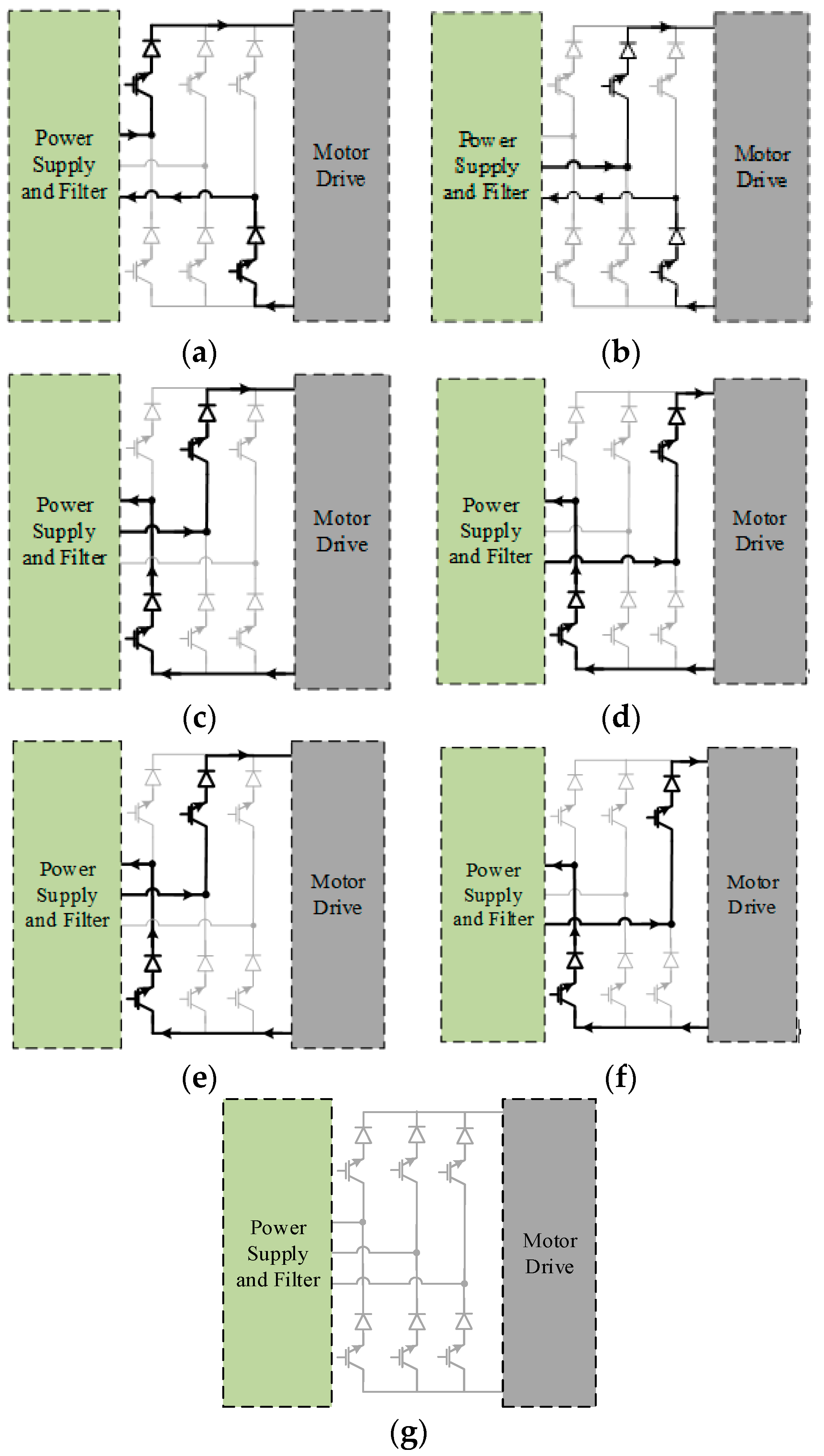
Through the analysis of the charger circuit, it is possible to devise operation modes associated with the rectifier circuit and operation modes associated with the inverters. The definition of these operation modes should take into consideration how the windings of the propulsion motor will be used. So, since the value of the DC inductor of the rectifier influences the input line current distortion and the switching frequency, two of the motor windings will be used in a serial connection. In accordance with this choice, there will be seven operating modes associated with the rectifier. Each of these operating modes is following described:
Mode 1: In this operation mode the power devices of the current source rectifier S
1 and S
6 are turned on (
Figure 2a) and the voltage applied to the motor windings is V
Cf13. This mode will influence directly the currents in inductors L
f1 and L
f3, since the capacitor voltages C
f1 and C
f3 will also be dependent on the i
o value.
Mode 2: In this operation mode the power devices of the current source rectifier S
2 and S
6 are turned on (
Figure 2b) and the voltage applied to the motor windings is V
Cf23. In this mode the most influenced currents will be i
Lf1 and i
Lf3.
Mode 3: In this operation mode the power devices of the current source rectifier S
2 and S
4 are turned on (
Figure 2c) and the voltage applied to the motor windings is V
Cf21. This combination will essentially affect the inductor currents i
Lf1 and i
Lf2.
Mode 4: In this operation mode the power devices of the current source rectifier S
3 and S
4 are turned on (
Figure 2d) and the voltage applied to the motor windings is V
Cf31. This mode mostly influences the inductor currents i
Lf1 and i
Lf3.
Mode 5: In this operation mode the power devices of the current source rectifier S
3 and S
5 are turned on (
Figure 2e) and the voltage applied to the motor windings is V
Cf32. The phase currents i
Lf2 and i
Lf3 will be most influenced.
Mode 6: In this operation mode the power devices of the current source rectifier S
1 and S
5 are turned on (
Figure 2f) and the voltage applied to the motor windings is V
Cf12. The currents i
Lf1 and i
Lf2 will be most influenced.
Mode 7: In this operation mode all the power devices are turned off (
Figure 2g). In this mode the current source rectifier is disconnected from the motor. All the three-phase current dynamics will be influenced, namely tending to reduce, as the inductor energy is transferred to the battery.
One of the critical aspects of the rectifier is the need for a DC inductor to work as an intermediate storage element between the grid and the batteries of the vehicle. This intermediate storage will be ensured through the control of the dual inverters and synchronized with the rectifier. Thus, to ensure the success of this procedure, there will be two operating modes. The first operating mode is when the energy is transferred from the grid to the motor windings. In this way, this operating mode will be associated with the rectifier operating modes 1 to 6. To ensure that the motor winding will operate as DC inductors the switches of the upper inverter S
U1, S
U2, and S
U3 and the switches of the lower inverter S
L5 and S
L6 must be in ON state (
Figure 3a). The second operating mode is associated with the transfer of the energy from the motor windings to the inverter battery. Thus, it must be ensured that the rectifier should be disconnected from the inverters. This will be achieved by operating mode 7. Regarding the switches of the inverters in this mode, all of them must be switched to the OFF state (
Figure 3b).
3. Control of the Charger
The proposed EV charger will be the controller in order to ensure a reference power and with near-unity power factor. In accordance with this, it is proposed a control system based on the dynamic model of the rectifier.
The model of the proposed current source rectifier, as an on-board charger, whose scheme is presented in
Figure 1, can be obtained considering all semiconductors being ideal while neglecting the losses of the inductors and capacitors. the operation modes will be also considered from the previous section, and the three-level variables
γ1,
γ2, and
γ3, in Equation (1) are assumed to be associated with the state of the power semiconductors. Based on the symmetrical and balanced three-phase system of
Figure 1, and applying Kirchhoff laws to the circuit, the state-space model, in the three-phase reference frame, is given by Equation (2).
Applying
αβ coordinates to the model of the current-source rectifier presented in Equation (2), the following equations are obtained in Equation (3).
For the controller design, consider the active and reactive powers to the input of the current source rectifier. From the instantaneous power theory [
41], the instantaneous active and reactive powers are expressed by:
From Equation (4) it is possible to obtain the required input AC currents function of the defined powers. Thus, these currents will be determined in accordance with the following equation:
To obtain a fast and robust controller, the sliding mode control [
41,
42,
43,
44] will be designed based on the state-space model presented in Equation (3) and Equation (5).
Considering the input AC current references,
isαref and
isβref, proportional to the active (
P) power and reactive (
Q) power, respectively, sliding surfaces for the input current can be obtained, in Equations (6) and (7).
Where
Kiα and
Kiβ proportional gains are chosen in order to impose an appropriate switching frequency.
Considering the sliding mode theory, the dynamics of the input current source rectifier variables have a strong relative degree of 2 [
42,
43]. Considering the feedback tracking errors, in the previous expressions, as the state variables the control equations will be given by:
In order to guarantee that sliding surfaces will be equal to zero, the following sliding mode stability conditions in Equations (10) and (11) must be verified:
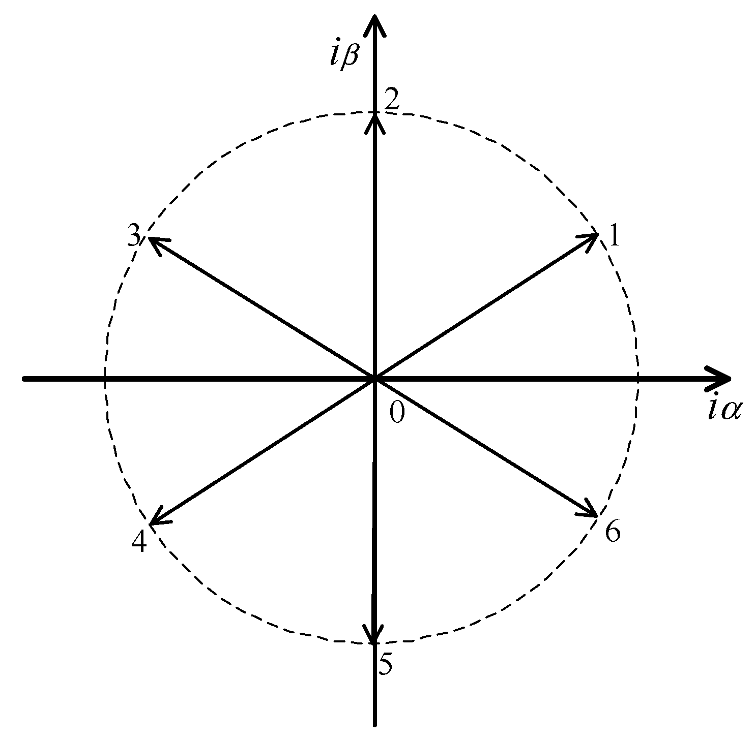
For the selection of the most suitable vector, a current vector modulator associated with the previous control equations is used. In this integrated charger system, from the point of view of the output current source rectifier, the motor drive will behave as a current source. In this sense and considering the several states of the current source rectifier switches, in the
αβ plane there are 16 vectors, 7 of them being distinct, as we can see from the space vector diagram presented in
Figure 4. To choose the current vector, two hysteretic comparators with the purpose to limit the switching frequency will be considered, to evaluate the output of the sliding surfaces, being 1 if they are positive or 0 if they are negative. Taking into consideration, for example, the situation in which the outputs of the two hysteretic comparators are both 1, then vector 1 should be selected.
There are some techniques [
45] to devise the choice of eight vectors from the two comparators, but in this application, the choice of the vector should not be made taking only into consideration the sliding surfaces and sliding mode stability conditions, but also the maintenance of the currents in the motor windings as constant as possible. Thus, to ensure the condition of the constant motor winding currents, the capacitor voltages must also be considered. As an example, let us consider again the situation in which the outputs of both hysteretic current comparators are 1, but the capacitor voltages
are negative and
are positive. In this situation, the vector near the second quadrant must be chosen. So, the vector nearest to the first quadrant (to ensure that the sling surfaces will move to zero) and to the second quadrant due to the capacitor voltages is vector 2. For the situation that the capacitor voltages
and
are negative then there is a conflict, since the quadrants under to be determined are the first one and the third one. The conflict is solved by choosing vector 0. On the other hand, the choice of this vector is also critical since it is the only vector that allows the transfer of the energy from the motor windings to the battery.
Table 1 presents the conditions for the choice of the current vector considering the sliding surfaces and capacitor voltages.
To control the charge of the EV batteries, there are normally two different approaches, constant power and constant voltage [
46,
47]. In constant power the control is normally ensured by a current controller. Indeed, the current reference of this controller is given by the power reference. The second approach is used to regulate the voltage of the batteries. Due to that, a voltage controller must be used. However, this controller can be associated with the current controller (that also allows to limit the current of the system) in a simple cascade structure. In this way, in the inner loop there is the proposed current controller (sliding mode) and in the outer loop there is a voltage controller that gives the reference of the current controller. For the voltage controller, a PI compensator can be used.
4. Tests Results
A detailed simulation using Simulink blocks and SimPower Systems blocks of the Matlab software, to model the proposed on-board integrated battery charger, was implemented.
To test the proposed solution, the charger was connected to a grid, with 230/400 VRMS, through input filter inductors with 5 mH and capacitors with 15 μF. For the three-phase induction motor, with open windings, an equivalent leakage inductance of 10 mH was considered. These windings are used as DC inductors of the charger. For the load (batteries) a voltage source with a value of 400 V each was considered. Due to these values, the rectifier was to operate in Boost mode. The switching frequency was not fixed since it was using a sliding mode controller. This frequency was the function of the hysteretic current comparators which used a width of 0.4 A.
The adopted controller was tested in different conditions allowing steady-state and transient analysis, under different system requirements.
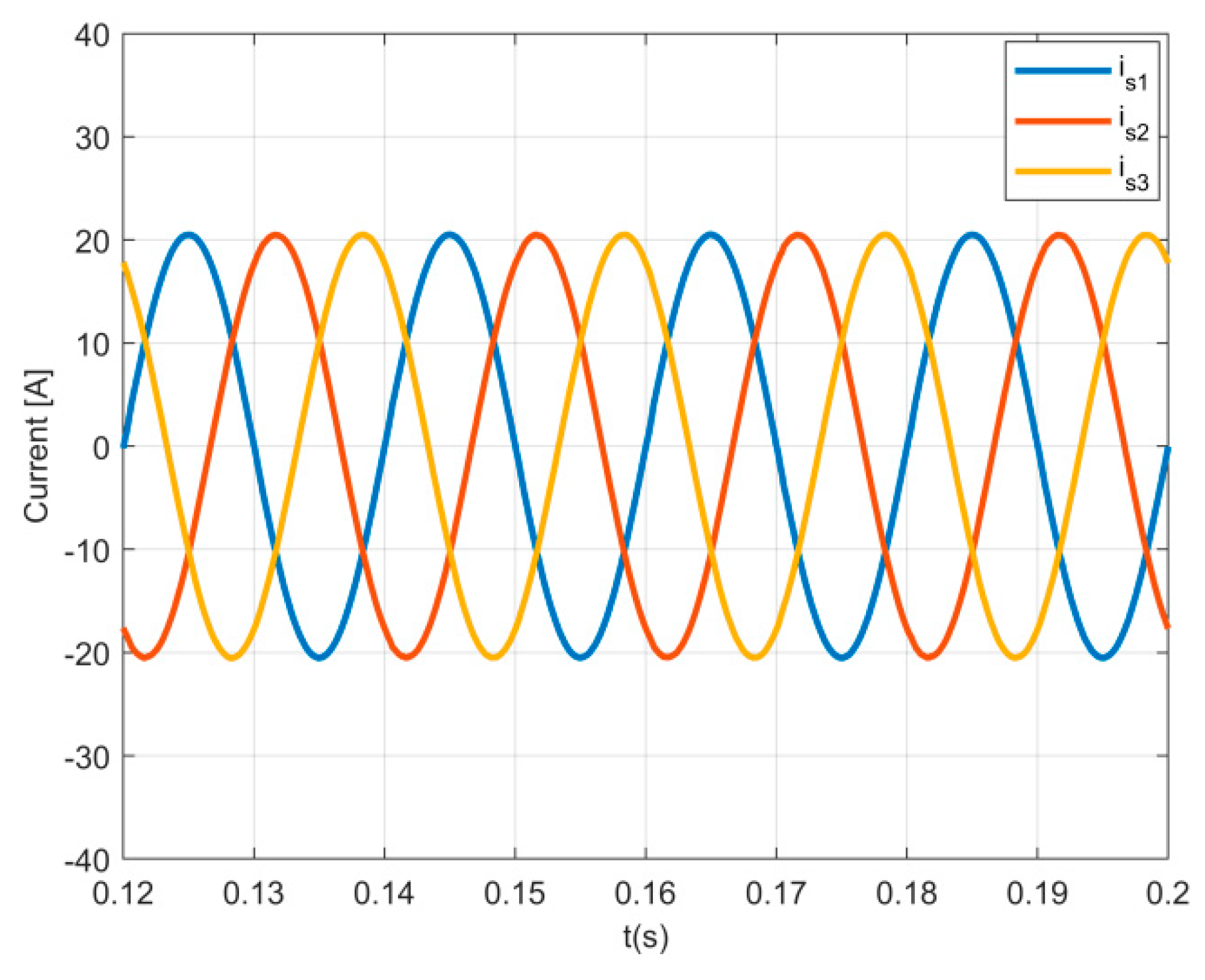
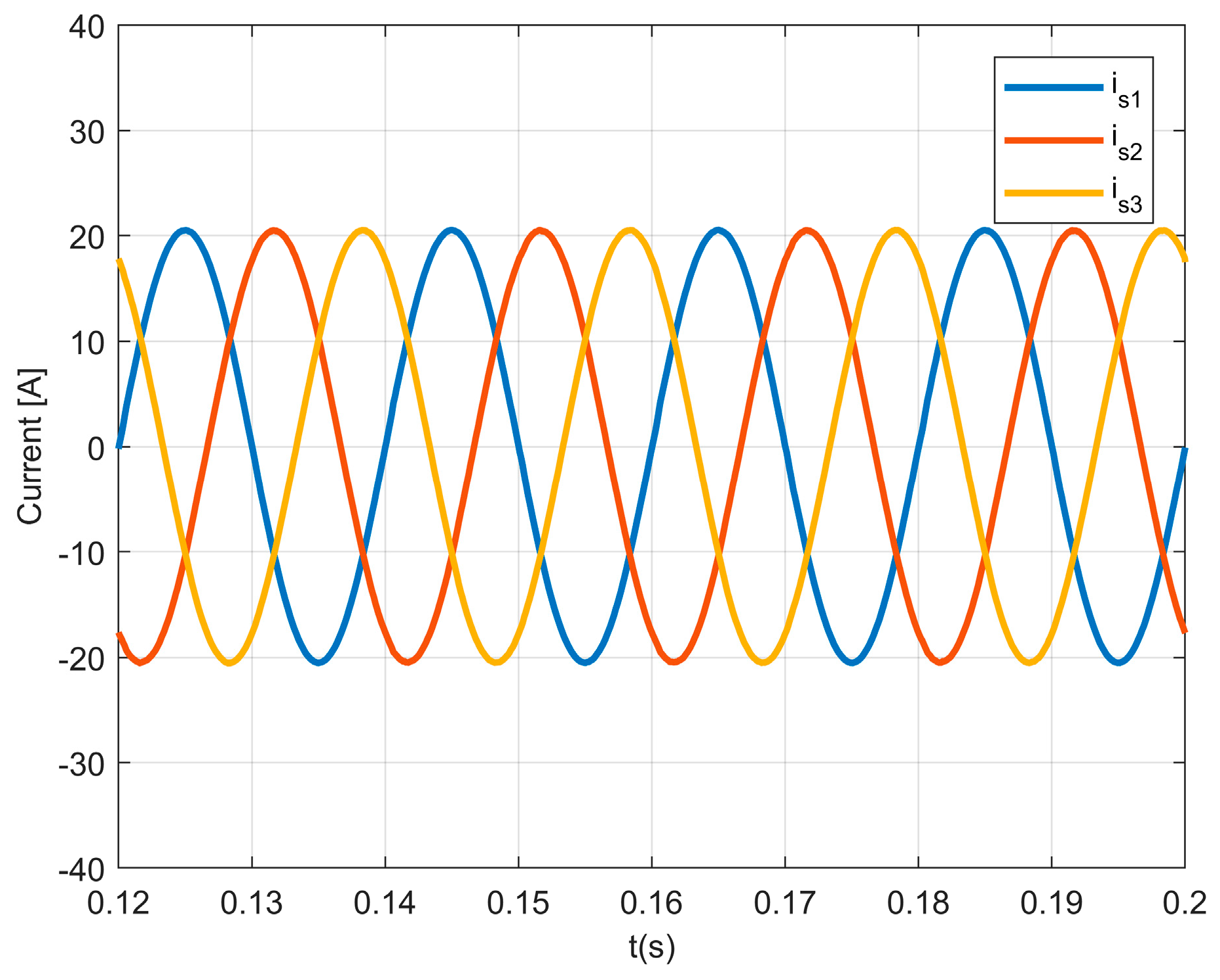
A steady-state analysis was made, considering the EV charging with a reference power of 10 kW (an AC per phase current of 14.5 A RMS). Results are shown in
Figure 5, which presents the three-phase charger input AC currents when the controller was tested in steady-state. Based on this result, it is possible to verify that the input currents are sinusoidal, with very low distortion.
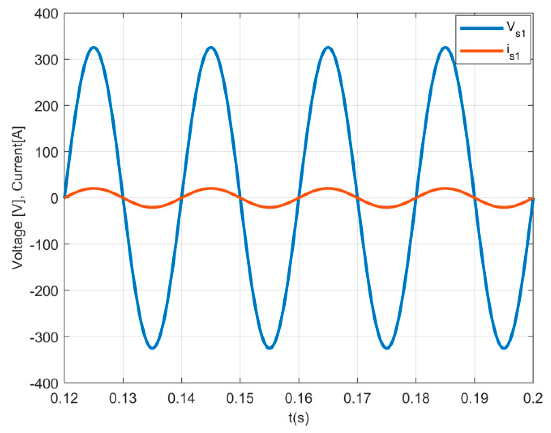
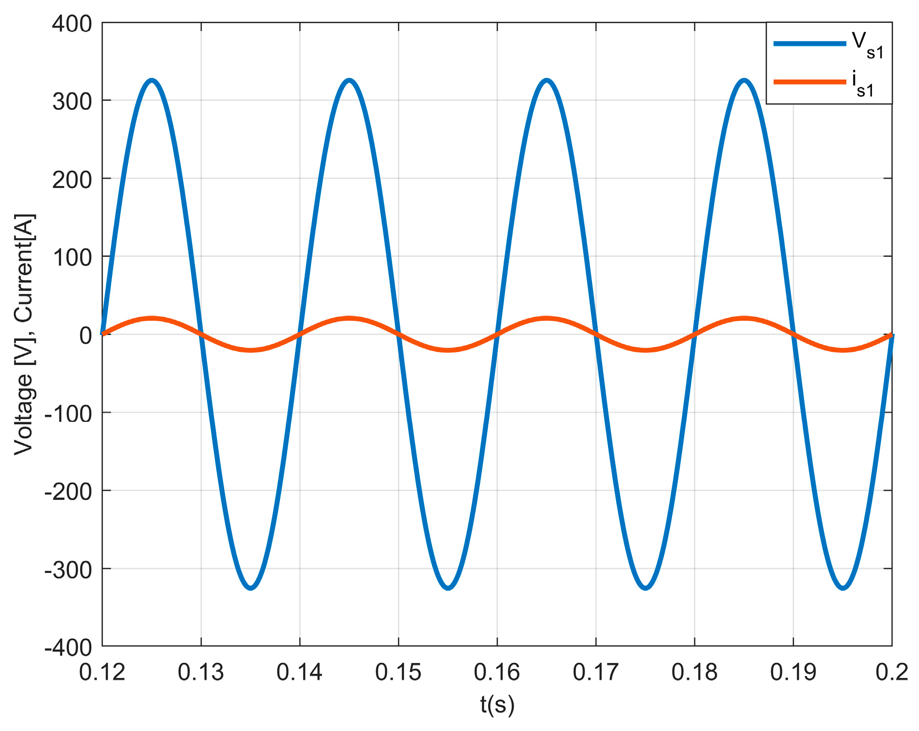
In
Figure 6, the results of the AC current and the grid voltage in phase 1 are presented. It can be seen in the figure waveforms that the current is in phase with the grid voltage of the same phase. This result confirms that the current source rectifier receives nearly only active power (near unity power factor). This can also be confirmed through the obtained low total harmonic distortion (THD) of the current, which is 3.5%. This shows that with this topology and control system, it is possible to obtain a low enough THD.
For the same conditions, in steady-state,
Figure 7 and
Figure 8 present the current in motor winding A (i
A) and the DC output current of the three-phase inverters (i
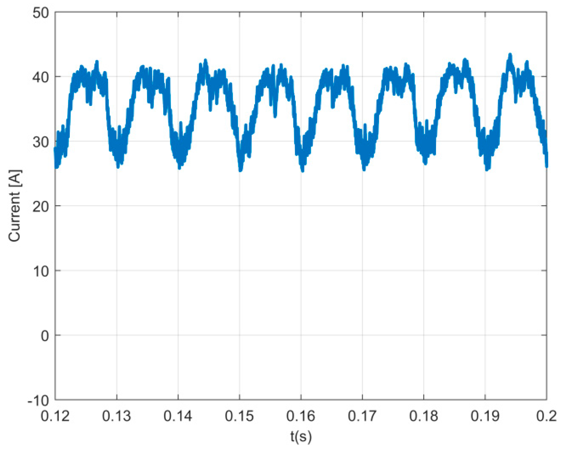
o1), respectively. The first figure shows that the motor windings will act as a DC inductor, being the intermediate storage system. Regarding the other current it is possible to verify that it has a similar top shape, although it has discontinuity modes. Indeed, only when the rectifier is in mode 7 (all switches of the inverter are in the OFF state) the current of the motor windings will flow through the DC side of the inverters.
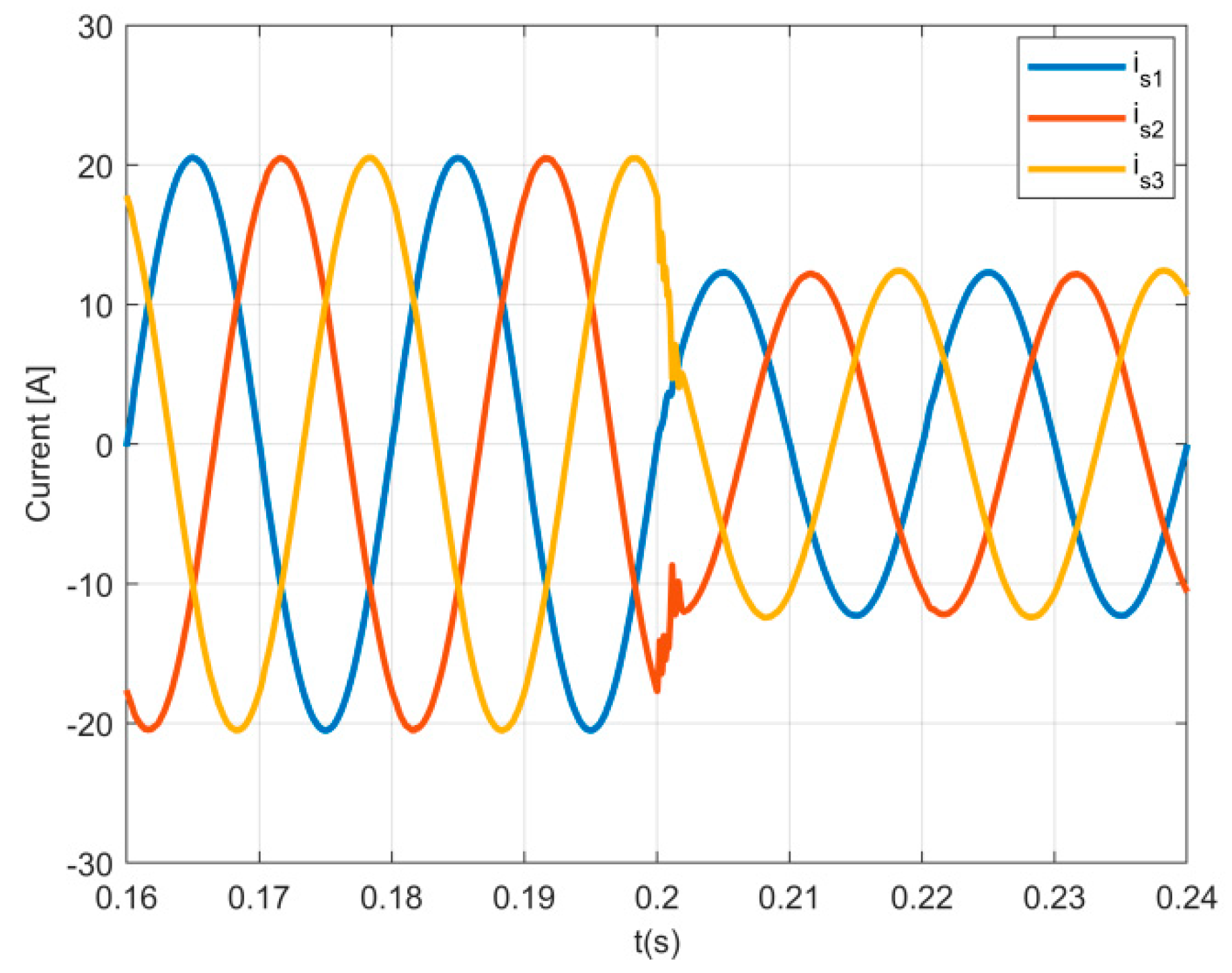
In order to test the performance of the EV charger controller, tests in transient conditions were also performed. The conditions for the tests were initially set to 10 kW (14.5 A RMS), and suddenly (at 0.1 s) changed to 6 kW (8.7 A RMS). The result of the three-phase charger input AC currents, presented in
Figure 9, shows that the controller based on sliding mode control has a fast dynamic response. In
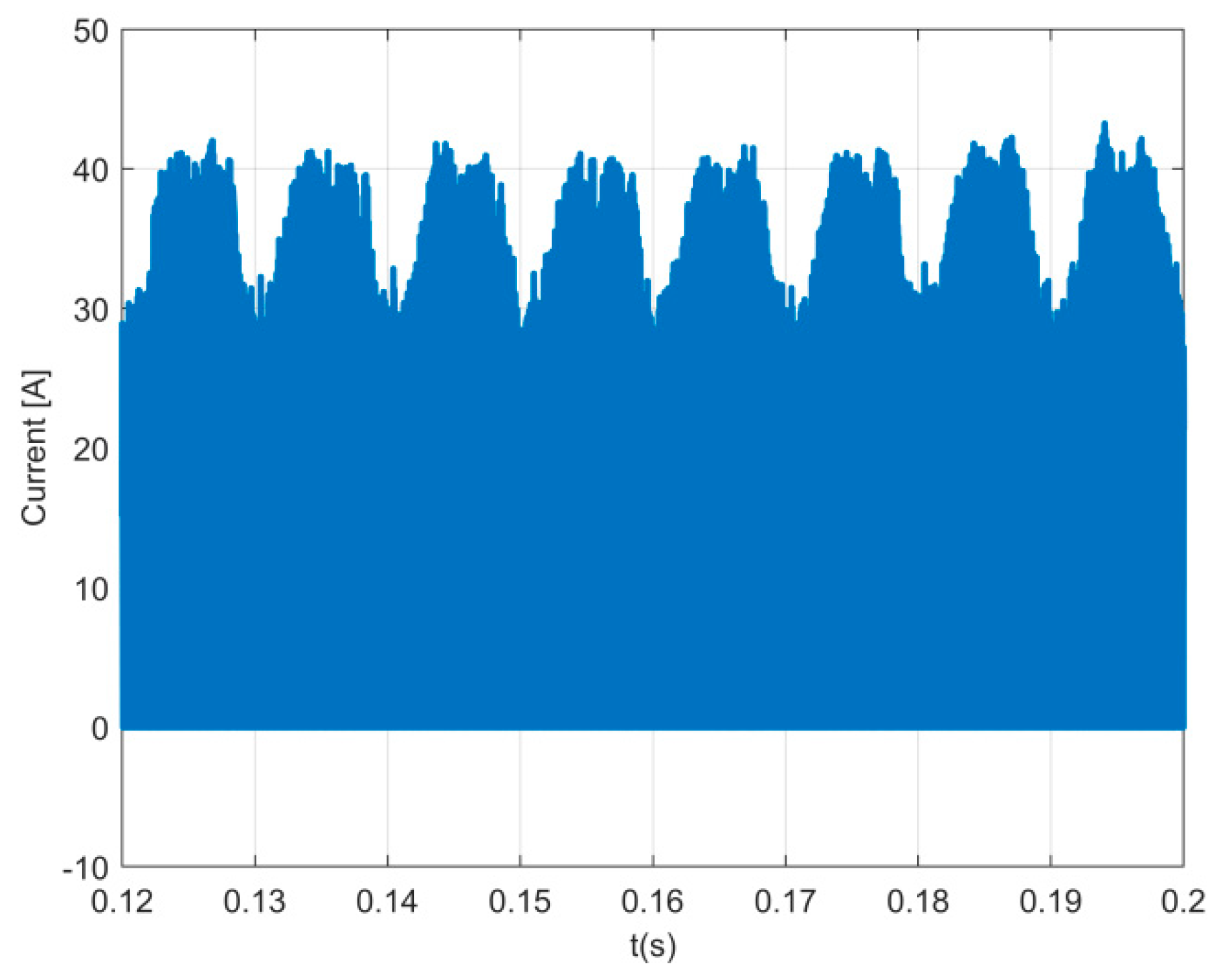
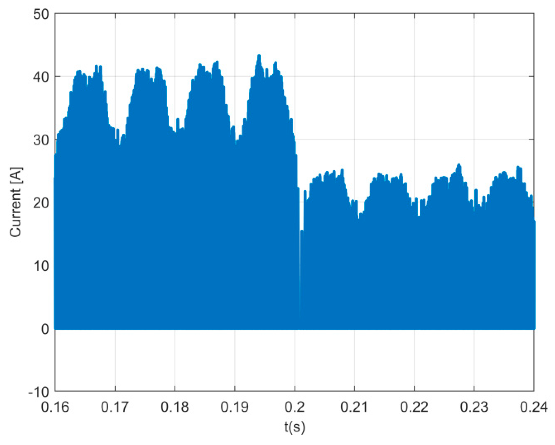
Figure 10 the results of the DC output current of the inverters are presented. From this waveform it is possible to conclude that this current is proportional to the amplitude of the input AC currents.
To verify the behavior of the EV charger in Buck operation mode, a steady-state analysis was done for the batteries with a value of 200 V each. It was considered again that the EV was charging with a reference power of 10 kW.
Figure 11 and
Figure 12 show the three-phase charger input AC currents and grid voltage and AC current in phase 1. These results show a behavior similar to the one in Boost mode. It is possible to conclude that the rectifier can be operated in Boost or Buck mode without degradation of their behavior. However, there is a slight increase in the distortion of the current to 4.1%, although still tolerated as seen in the figures.
5. Experimental Results
To support the theoretical assumptions and expectations, as well as the simulation studies, a low power prototype was used to perform additional tests. The charger was connected to an AC power source with 200 Vmax and 50 Hz. For the input filter, 5 mH inductors and capacitors with 15 μF were used. The battery was implemented using two voltage sources with a value of 250 V each. For the hysteretic current comparators was used a width of 0.2 A. An oscilloscope TDS3014C was also used to acquire the waveform signals.
The obtained experimental results from the low power prototype of the charging process are shown in
Figure 13,
Figure 14,
Figure 15 and
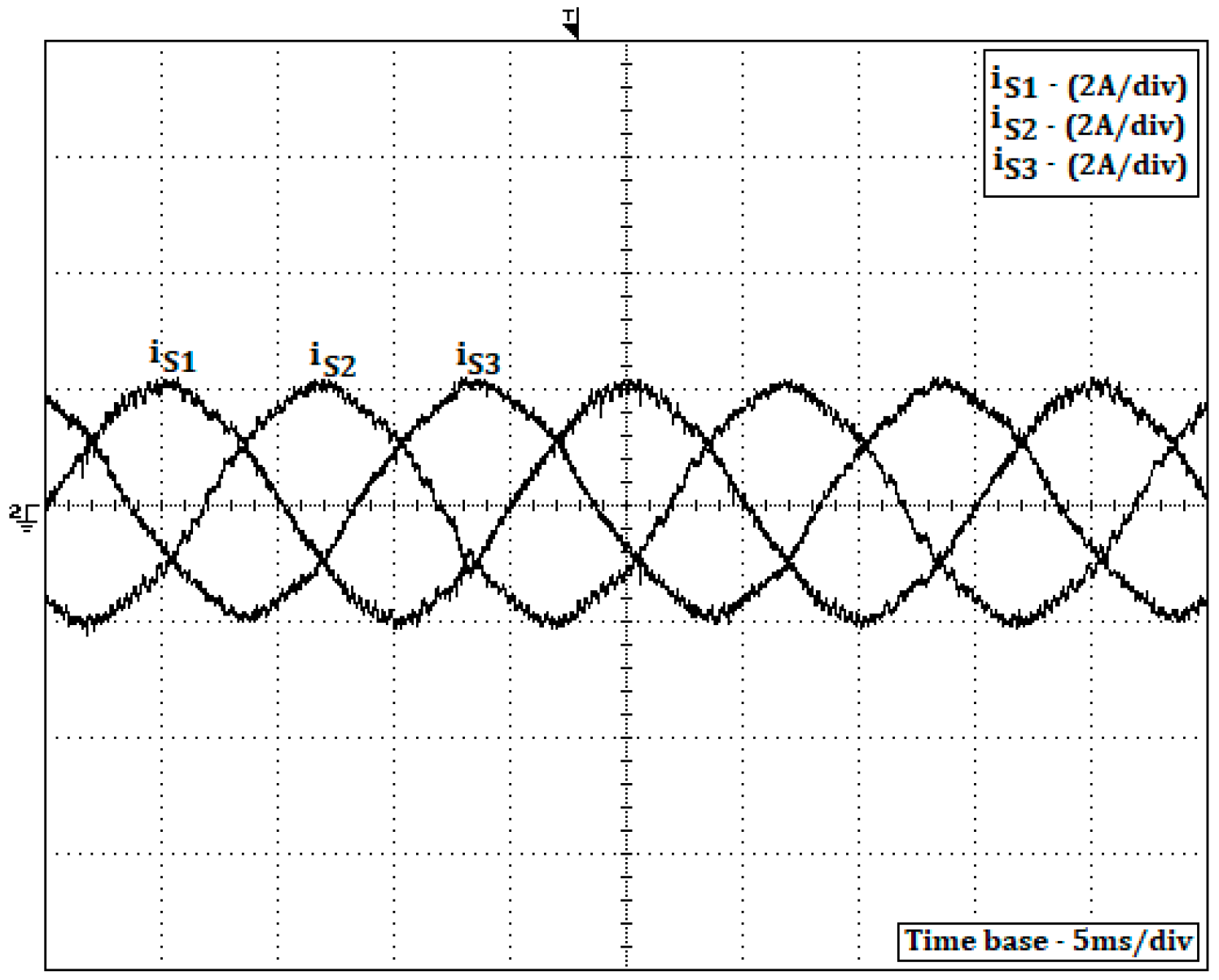
Figure 16. For the data presented in those figures, a reference power of 600 W was adopted, which gives a current amplitude of 2 A. From
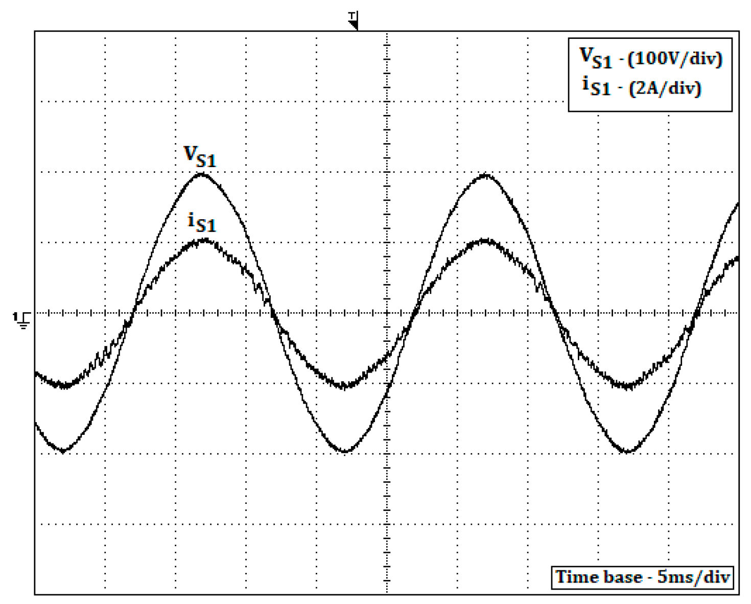
Figure 13, it is possible to see that the three-phase charger input currents are in accordance with the reference value and present a shape that is nearly sinusoidal. This can also be confirmed through the obtained low total harmonic distortion (THD) of the current, which is 3.9%. The charge at unity power factor can be confirmed by
Figure 14, which presents the grid voltage and rectifier AC current in phase 1. Indeed, it is possible to confirm that the current in phase with the grid voltage.
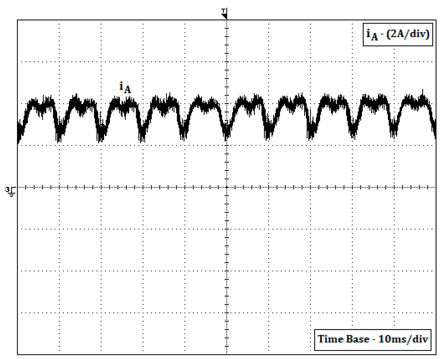
The current in the motor winding during this charging process can be seen in
Figure 15. Through this figure, it is possible to confirm that the windings will act as DC inductors since the current has a small ripple. The output DC current of the inverters can be seen in
Figure 16. As expected, this current is similar to the results in
Figure 8, confirming that only when the rectifier is in mode 7 (all switches of the inverter in the OFF state) the storage energy in that winding will be transferred to the batteries.
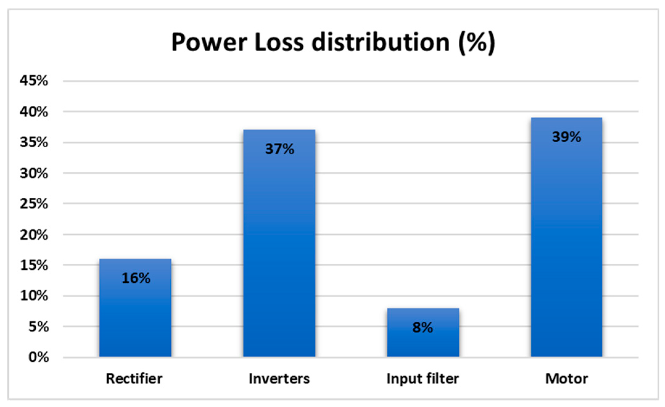
Regarding the overall efficiency of this charger for the conditions of this test, a value of 86% was obtained. To see the percentage of the losses associated with this efficiency considering the several parts of the charger, the loss breakdown of the charger is presented in
Figure 17. From this figure it is possible to verify that the majority of the losses are associated with the propulsion system (motor and inverters). Comparing with the known integrated EV chargers, it is possible to see that it presents similar values. This comparison was made considering the chargers presented in the works [
21,
22,
24,
25,
28,
31], in where their efficiency is 90%, 87%, 89%, 82–92%, 76%, and 83%.

 ,
, 


