Abstract
This paper presents a set of simulations to evaluate the digital data transmission performance of a two-user Fiber-Radio system that shares the same optical and wireless link. For this purpose, at the optical stage, the Optisystem software 21.1.0 is used to simulate the transmission of two digital signals at a bit rate of 2.4 Gbps through a 100 m single-mode standard fiber (SM-SF). To implement the use of a single optical link for two users, the Wavelength Division Multiplexing (WDM) technique is used. Subsequently, the wireless stage is evaluated in MATLAB R2023a by using the NOMA scheme, and the wireless transmission and data recovery are shown and explained in detail. In the wireless stage, four factors that affect the transmitted signal are considered: noise, two types of fading, and Co-channel interference. Performance of the wireless system is evaluated using statistical tests. The simulation set has potential applications in the performance evaluation of Fiber-Radio systems for outdoor environments due to their satisfactory operation at distances of up to 500 m from the transmitting station. Furthermore, the proposed system could be applied to cellular telephony, the Internet of Things (IoT), and sensor signal transmissions for industrial or agricultural uses.
1. Introduction
Continuously, advances in communication technologies continue. These technologies exist due to a growing demand not just for the quantity of electronic communication devices (radios, TV’s, mobile phones, and computer equipment) and services (radio, HDTV, telephony, and Internet) available to users, but also for the increasingly diverse services that the devices are capable of providing, which has made it possible to transmit information in more varied, rapid and efficient ways. The constant evolution of communication systems necessitates new approaches to utilizing the resources they employ. Combining optical and wireless technologies creates hybrid communication networks that leverage the high bandwidth of optical fibers associated with the mobility and coverage of wireless systems, enabling advanced applications such as future 6G networks. In this regard, a two-user Fiber-Radio system with a NOMA scheme is presented.
The Fiber-Radio scheme is a technological solution that utilizes optical fiber to transport signals to transmitting antennas and radiate them to the recipients, leveraging the characteristics of both optical fiber and wireless transmission [,,]. This is illustrated in Figure 1. At the CS (Central Site), an electrical signal containing the information to be transported modulates a light beam, which is injected into the optical link that covers the required distance. Subsequently, in the RRU (Remote Radio Unit), the light beam is recovered, and the electrical signal is delivered, which is finally radiated by the antenna.

Figure 1.
Fiber-Radio link.
Currently, in terms of coverage, security, and reliability, Fiber-Radio technology has become a very robust option. This system is being implemented to improve performance and provide greater bandwidth and range for mobile communications. These systems have advantages, including lower attenuation and dynamic resource allocation, and can transfer high-frequency signals that support next-generation network technologies [].
On the other hand, NOMA is a multi-user access scheme for wireless transmissions. This means that two or more signals that need to be transmitted can be combined into a new signal without interfering with or interrupting each other. Regarding wireless transmission systems and cellular telephony, several access schemes have been developed; the main ones are FDMA (implemented in 1G), TDMA (implemented in 2G), CDMA (implemented in 3G), and OFDMA (implemented and currently used in 4G and 4.5G) []. The new generation strategy is the NOMA multi-user access scheme [] (whose use is considered for 5G in addition to OFDMA), which performs power multiplexing. The key is to have carrier signals that can be modulated at equal frequencies and have significant differences in their power levels. By combining these signals into a single signal, it is possible to establish more than one link on the same frequency, considering the level differences between the powers. This is illustrated in Figure 2a, which shows the allocation of a single power per frequency (as in OFDMA), compared to the allocation of more than one power per frequency (as in NOMA), as shown in Figure 2b.

Figure 2.
(a) Orthogonal multiple access (as used in OFDMA). (b) Non-orthogonal multiple access (NOMA) [].
Figure 3 shows a downlink NOMA scheme for two users, considering one signal (destined for user 1) with the lowest power level, and the other (destined for user 2) with the highest power level. The total wirelessly transmitted NOMA signal consists of the sum of those signals. Because the NOMA scheme distinguishes signals by assigning different power levels, the Quadrature Phase-Shift Keying (QPSK) [] digital modulation is the most suitable for this purpose in this work. This type of modulation performs phase modulation while the carrier signal maintains its frequency and amplitude. It provides high robustness to the pursued objective, allowing the assignment of a power level as much as necessary to each signal without affecting the transmitted data. In addition, QPSK is chosen because it is currently used (in addition to 16QAM) [] in 4.5G and 5G technologies.
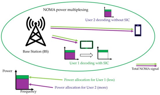
Figure 3.
NOMA downlink for two users with SIC [].
To separate the data, the user whose modulation had a higher power allocation recovers its part of the signal by demodulating the total received signal, while the signal from the other user is considered as noise. For the other user, the signal with the lower power level is recovered by subtracting the signal with the higher power level from the total received signal. This procedure is known as Successive Interference Cancelation (SIC) [], also illustrated in Figure 3. Therefore, SIC is a suitable technique for separating and recovering the summed signals within the NOMA scheme.
Fiber-Radio schemes have been studied for several years. Works that have been reported in the available literature refer not just to their use, but also to their evolution. For example, in [], a Fiber-Radio link with double spectral efficiency transmission and compensation of power fading caused by chromatic dispersion is proposed and experimentally demonstrated. In [], a system known as Power-over-Fiber (PoF) is proposed for power transmission through optical fiber. In [], the functionality of the Fiber-Radio scheme with different simultaneous transmission frequencies is demonstrated, using a digital multiplexer for frequency and channel selection. A scheme called Radio-Fiber is characterized in [], where a microwave signal provided by a receiving antenna is supplied to an optical modulator. The proposal in [] outlines a hybrid scheme, Fiber-To-The-Home (FTTH) network that merges a mobile wireless application system using a dual optical modulator and two different signals (high-frequency and baseband). In [], a Fiber-Radio scheme is developed using a radiating cable for wireless transmission. In [], a Fiber-Radio system based on 16QAM modulation is simulated using a polarization modulator. In [], a Fiber-Radio project for implementing a digital television network in Indonesia is described. The design of a passive optical network with a Fiber-Radio scheme is reported in []. In [], the analysis for different modulation formats for Fiber-Radio schemes is carried out.
Regarding NOMA, existing works refer not only to its use but also to its development and evolution. Given the growth in service demand, recent progress in NOMA systems is discussed in [], where a review of multiple access technologies developed over the last 50 years is provided, analyzing their integration with emerging technologies. In [], a NOMA system combined with an 8-antenna Multiple Input–Multiple Output (MIMO) is simulated, forming an 8 × 8 NOMA-MIMO scheme. In [], the performance of NOMA is evaluated in comparison with OFDMA. In [], a comparative study of different algorithms used in NOMA for power allocation is presented. In [], a technique is proposed to improve the initial access capacity of users in a 3GPP non-terrestrial network using NOMA. In [], to improve the cell-edge user rate, cooperative NOMA is proposed, where the nearby user acts as a relay and retransmits the cell-edge user data. In [], the Age of Information (AoI) is used to examine the current state of existing data on NOMA and SIC. In [], criteria for power level assignments in a NOMA scheme for an arbitrary number of users are studied. In [], a study of NOMA efficiency in multi-antenna networks is reported. Finally, a simulation and its analysis on the Bit Error Rate and signal outage probability in a NOMA scheme are carried out in []. These works demonstrate that both the Fiber-to-Radio link and the NOMA scheme have features and advantages that were previously unavailable, making them essential options for the future of telecommunications.
In the past, we have successfully presented a Fiber-Radio scheme serving one user [], carrying out the electro-optical stage simulated in VPI Photonics [] and evaluating the wireless part in MATLAB, considering the four affecting factors (two types of fading, AWGN, and co-channel interference). The Bit Error Rate (BER) and Signal-to-Interference-plus-Noise Ratio (SINR) statistical tests were used to evaluate the performance of that approach. Now, the work in [] has been improved. The main difference resides in the use of a single optical and wireless link shared by two users. Furthermore, a NOMA scheme is integrated into the wireless stage.
After this introduction, this paper is organized as follows: Section 2 describes the optical and wireless simulation procedures. In Section 3, the performance of the NOMA wireless part is shown and analyzed. Discussion of results is presented in Section 4. Finally, the conclusions are outlined in Section 5.
2. Simulation Section
This section is divided into two subsections: first, the optical stage simulation is shown. Subsequently, the second one describes the evaluation of the wireless stage, explaining in detail the procedure carried out for the NOMA scheme.
2.1. Optical Stage Simulation
In this subsection, the electro-optical stage simulation is described. To achieve this goal, Figure 4 presents the corresponding block diagram, which is subsequently simulated using Optisystem software []. To implement the use of an optical link for two users, the optical multiplexing technique known as Wavelength Division Multiplexing (WDM) [] is used.
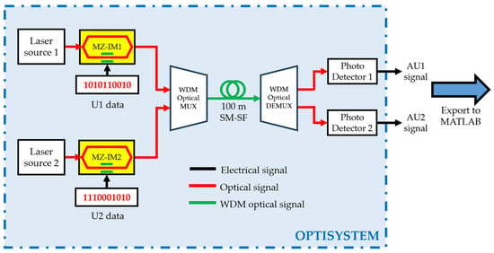
Figure 4.
Communication link of two digital signals via optical fiber using WDM.
The features of this simulation are the following: two bit streams, each one at a rate of 2.4 Gbps (bit rate used commercially according to the communication standards), two Distributed Feedback Lasers (DFBs) as optical sources emitting at wavelengths λ1 = 1548.26 nm and λ2 = 1550.22 nm (wavelength used in standard optical communication systems), at an optical power of 0 dBm (1 mW), two Mach–Zehnder (MZ-IM) intensity modulators, one WDM optical multiplexer, 100 m (commonly used length in a short range optical transmission link) [] of SM-SF, whose chromatic dispersion (D) and attenuation (α) parameters at 1550 nm are 16.75 ps/nm·km and 0.2 dB/Km, respectively, one WDM optical demultiplexer, and two PDs that recover the modulated optical signals and output the electrical signals with the transmitted bit values (signals AU1 and AU2). Figure 5 shows the diagram corresponding to the electro-optical arrangement simulated in Optisystem.
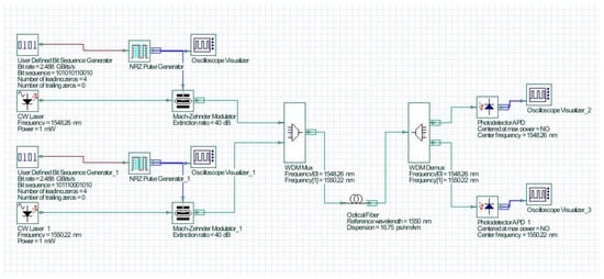
Figure 5.
Communication link between two digital signals via an optical fiber using WDM in the Optisystem environment.
The Optisystem software enables the signal visualization in a graphical manner, as well as the export of corresponding files with .txt or .csv extensions. Figure 6a,b graphically show the bit sequences for U1 and U2 proposed in the simulation to be transmitted (1010110010 and 1110001010, respectively). These sequences are proposed because they enable graphical observation and potential anomalies in the signals throughout transmission, such as broadening or inversions. The digital signals are generated and displayed by the virtual generator and the interface oscilloscope. A “0” value space, a start bit, and an additional “0” are also added at the beginning of each sequence to maintain the integrity of the transmitted data.

Figure 6.
(a) Bit sequences for U1. (b) Bit sequences for U2.
As is illustrated in Figure 4 and Figure 5, each data signal modulates through its respective MZ-IM, a light beam from its corresponding virtual DFB optical source. The modulated beams are coupled into the WDM multiplexer and transmitted as a single beam through the optical fiber. Ultimately, the optical signal is delivered to the WDM demultiplexer, which separates the signals and routes them to the virtual PDs. Each of these PDS supplies the AU1 and AU2 signals shown in Figure 7a,b, respectively. They are displayed on the virtual oscilloscope and stored in .csv files.
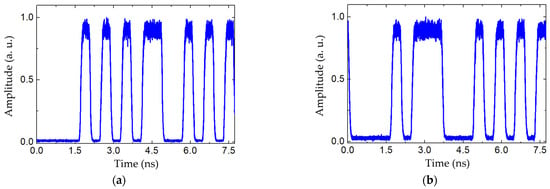
Figure 7.
(a) AU1 signal, provided by the corresponding PD. (b) AU2 signal, provided by the corresponding PD.
2.2. Processing Signal and Wireless Stage Simulation
The signals obtained from the simulated optical communication scheme are exported to MATLAB for processing. This consists of normalization, debugging, and BR correction of the digital signals. The cancellation of the sequence repetition and the initial bit is also performed. This is illustrated in Figure 8, where the green dotted boxes indicate the processing performed by MATLAB.

Figure 8.
Importing signals AU1 and AU2 for processing in MATLAB.
After this process, MATLAB delivers the signals shown in Figure 9a,b, named, respectively, BU1 and BU2.
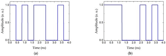
Figure 9.
(a) Cleaned and normalized digital data BU1. (b) Cleaned and normalized digital data BU2.
Within MATLAB, these signals are applied to the NOMA scheme to evaluate wireless transmission, as shown in Figure 10.
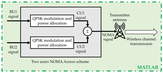
Figure 10.
Details of the NOMA scheme.
In the NOMA scheme, processing is carried out in two stages: first, the signals are modulated in QPSK format, and a power level is assigned for each signal (see Figure 11a,b). This gives the signals CU1 and CU2, which are summed in the second stage. The result of this addition corresponds to the NOMA signal illustrated in Figure 12.
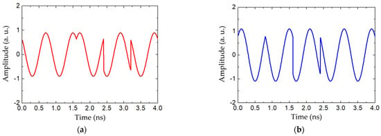
Figure 11.
(a) QPSK signal CU1. (b) QPSK signal CU2. These signals are parts of the NOMA scheme.
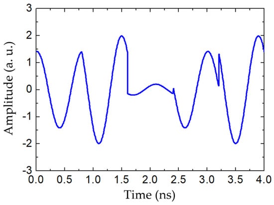
Figure 12.
The delivered signal by the NOMA scheme to the transmitting antenna.
For wireless networks, the coverage area for mobile users consists of hexagonal cells because they provide an equidistant array of antennas, are symmetrical, and supply full coverage. In this work, a specific case involving two wireless receivers, U1 and U2, placed within one of the three sectors of the central Base Station (BS0) cell is analyzed, as is depicted in Figure 13. The virtual antenna is located at BS0, as described in [], and it is considered in its coverage cell of radius 500 m. U1 and U2 move within the cell sector. Their positions are determined by the Randi function, available in MATLAB. The six cells surrounding BS0, corresponding to the nearby base stations (BS1 to BS6), are also considered [].
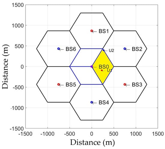
Figure 13.
Illustration of the coverage area with U1 and U2.
Mathematically, the transmitted NOMA signal is defined as []
where
n corresponds to the total number of receiver users.
k = 1, …, n is each receiver user; in this work, k = 1, 2.
represents the power allocation factor corresponding to each user.
denotes the transmitted modulation symbol containing the information destined for each receiver.
The transmitted signal , affected by losses corresponding to each user, is given by [,]
where
is the distance between BS0 and each user; the positions of the users are uniformly distributed inside the coverage area.
µ is the propagation loss exponent with values between 2.5 and 6, or even higher, depending on the type of environment. As an urban environment is being considered, then µ = 4 [].
h is a Rayleigh random variable whose model fading is caused by multiple signal paths (fast fading) with standard deviation Δ [].
represents the environment fading; it is a log-normal random variable () that represents shadowing losses (slow fading). It is defined as a function of the Gaussian random variable ζ, with standard deviation σ [,].
Co-channel interference is caused by signals transmitted by the nearby base stations (BS1 to BS6) using the same operating frequency, and is added to the transmitted signal; for each receiver, it is defined by []
where j = 1, …, m is the number of each nearby transmitter, and is the received signal corresponding to each receiver. In this work, .
The total signal reaching each receiver is given by []
where is defined as the Additive White Gaussian Noise (AWGN) signal [] with mean and standard deviation σ.
The forward link performance of the wireless system is evaluated in terms of the Signal-to-Interference-plus-Noise Ratio (SINR), given by [,,,,]
The SINR, expressed in decibels, is given in [,]
BER is expressed as a percentage of erroneous bits concerning the sent bits.
Environment and multipath fading, as well as AWGN and CCI, influence reception in particular and different ways in U1 and U2 because they are not at the same distance from BS0 nor the same position within the sector. Therefore, within the process evaluated in MATLAB, the factors are modeled by the corresponding random variables individually for each receiver. The wireless transmission channel is represented in Figure 14a,b for U1 and U2, respectively, illustrating the effects on the signals within each black dotted box.
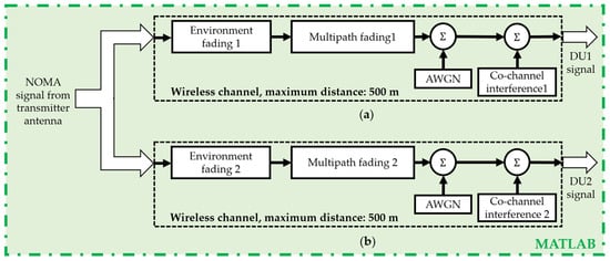
Figure 14.
Wireless channel modeling for user 1 (a) and user 2 (b).
The signals DU1 and DU2, received by U1 and U2, are illustrated in Figure 15a,b, respectively.
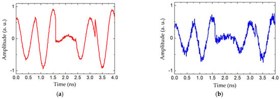
Figure 15.
(a) Signal received by U1. (b) Signal received by U2.
Figure 16 shows the virtual receivers that decode the wireless signal. The information recovery process is described below.
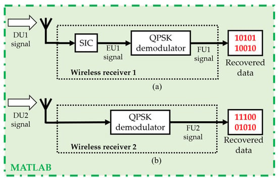
Figure 16.
Wireless receivers U1 (a) and U2 (b).
The receiver corresponding to U1 is assigned a lower power value since it has better channel conditions; thus, it is necessary to perform an SIC process to recover the signal part that corresponds to it, designated as EU1 (Figure 17). Finally, this signal is demodulated, obtaining the signal FU1. Since the power allocation is higher for user U2, this signal is directly demodulated, generating the signal FU2.
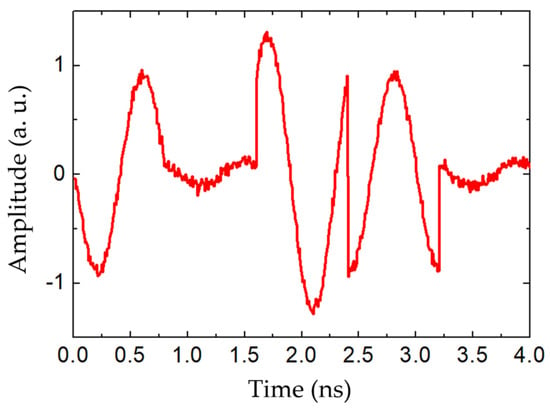
Figure 17.
Signal EU1, corresponding to U1.
The signals shown in Figure 18a,b correspond to FU1 and FU2, respectively, obtained from the corresponding demodulations, which are the digital data provided by the virtual generators in the Optisystem simulations (10101100 and 1110001010). Note the good similarity with Figure 6a,b, respectively.

Figure 18.
(a) Recovered bit values at the end of the wireless link for U1. (b) Recovered bit values at the end of the wireless link for U2.
To determine which user should be assigned a higher power level, the process outlined below is followed. Initially, within NOMA, after QPSK modulation for each user, one user is assigned a higher power level before the sum of the signals is calculated, for example, U2. Due to the nature of the NOMA scheme, the use of a percentage in pairs of values for the involved users is required; it is only necessary that the power levels differ between them. Simulation tests revealed that the optimal results were achieved with a 60-40 power percentage ratio. Subsequently, after adding the signals and transmitting them, the numerical values for fading, AWGN, and CCI are determined using their respective random variables, as well as the positions of the users within the sector. At reception, the channel conditions are found by measuring the SINR and the CCI level for each user. If user 1 has better channel conditions than user 2, the power level assignment is maintained; that is, the user with the best channel condition is assigned the lowest power. On the contrary, if better channel conditions are found for user 2, the power level assignment is interchanged, allowing user 1 to have a higher level. This ensures that each user has a power level according to their channel condition in each execution of the evaluation in MATLAB. This process is illustrated in the flow diagram shown in Figure 19.
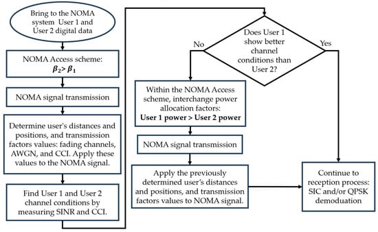
Figure 19.
Flow diagram describing the NOMA power allocation process.
3. Wireless Stage Analysis and Results
A Monte Carlo-based approach is used to simulate discrete events to evaluate the functionality of the proposed NOMA scheme. The simulation parameters are presented in Table 1. The σ (slow fading standard deviation) and Δ (fast fading standard deviation) values are those that, by standard, characterize propagation in urban environments [,]. Individually, the evaluation of the wireless transmission performance is carried out in terms of the SINR and the BER for each receiver.

Table 1.
Simulation parameters considered for an urban outdoor zone [,].
The distances from U1 and U2 to BS0 vary from 1 to 500 m within their corresponding sector, and their positions determine the impact of co-channel interference. The levels of fading, noise, and interference are modeled based on the standard deviation values of the random variables that determine them for the simulation. This form of modeling allows proposing different noise levels, which is the factor with the greatest possible variation [,]. Since co-channel interference and fading are modeled by random variables, and considering that U1 and U2 move within their corresponding sector, the simulation results are averaged in terms of SINR and Bit Error Rate (BER) percentage for different noise levels. To establish the appropriate confidence interval for simulating the wireless stage and obtain reliable statistical data, 1000, 10,000, 30,000, 60,000, and 100,000 repetitions of the MATLAB code are performed, and the average of the obtained values is obtained. It is observed that, within the range of 60,000 to 100,000 repetitions, the difference between the averages is negligible. Thus, 60,000 repetitions are established as the confidence interval.
Figure 20 shows graphically how the noise level influences the BER percentage for each user. In both plots, it can be observed that with a standard deviation of AWGN of 1 × 10⁻¹² and lower values, the information can be recovered; this system is then functional in noise levels equal to or lower than this value. Figure 21a shows the SINR (dB) resulting from the same AWGN standard deviation levels for user 1, while Figure 21b indicates the same for user 2. As the AWGN parameter decreases, the SINR parameter increases, stabilizing at an AWGN standard deviation of 1 × 10⁻¹⁴. Finally, in Figure 22a, it can be observed that for user 1, higher SINR values result in lower BER values. A similar situation for user two is illustrated in Figure 22b. This can be observed in Table 2 and Table 3, respectively.
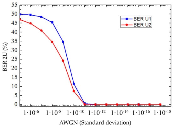
Figure 20.
BER percentage vs. AWGN standard deviation for U1 (blue trace) and U2 (red trace).
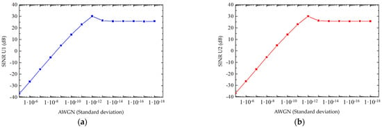
Figure 21.
(a) SINR vs. AWGN standard deviation for U1; (b) SINR vs. AWGN standard deviation for U2.

Figure 22.
(a) Relationship between SINR and BER percentage for U1; (b) Relationship between SINR and BER percentage for U2.

Table 2.
Relationship between SINR and BER percentage for U1.

Table 3.
Relationship between BER and SINR percentage for U2.
Figure 22a and Table 2 show a SINR threshold value of 26.46 dB, above which the BER value is 0 for U1. The same situation is observed in Figure 22b and Table 3, which show a threshold value of 26.29 dB, above which the BER value is 0 for U2.
Figure 23 of [] is used to compare the relationship between SINR and BER percentage, because it is very similar to the NOMA scheme used in this work. That is, a SINR threshold value of 24.90 dB, above which the BER value is 0. A curve representing ideal conditions has been added (red trace), which aligns with the results reported in most of the related works. It shows that, in the 0–10 dB SINR region indicated within the red rectangle, the BER remains below 0.001. Figure 24 shows the performance curve of an OFDMA access scheme for SIR (not SINR) versus BER under ideal conditions. []. Both technologies exhibit very similar performance under the same conditions.
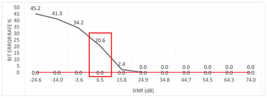
Figure 23.
BER percentage vs. SINR is evaluated in previous work []. The 0–10 dB SINR range is indicated in the red rectangle. The red trace indicates the system response under ideal conditions.
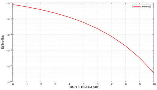
Figure 24.
BER percentage vs. SIR in an OFDMA link [].
In this work, the SINR values are not arbitrary; these are the result of the AWGN values level indicated in Figure 21.
4. Discussion
This set of simulations focuses on optical and wireless communications. Specifically, a Fiber-Radio system is used to transport data via optical fiber and distribute it wirelessly through antennas. The use of Fiber-Radio systems is the result of the increasing need for future 5G mobile networks to handle a wide range of traffic types, from broadband to high-bitrate applications. In this context, the high performance of optical fiber for fast data transport and the high mobility enabled by antennas for wireless transmission are both exploited. This work is devoted to the study of the NOMA (Non-Orthogonal Multiple Access) scheme, as it is considered a potential technology for 5G. Specifically, Fiber-Radio schemes are proposed to transport two data signals through a single optical fiber link, followed by an analysis of their wireless transmission. The fiber-optic transmission results are presented from simulation responses obtained using Optisystem software. The wireless link and the NOMA scheme are evaluated through numerical simulations conducted in MATLAB. These evaluations account for inherent impacts of wireless transmissions, such as fading, noise, and interference. Additionally, statistical tests are performed to consider the effects of different noise levels and receiver locations within various positions in the cell coverage sector. The goal is to improve system performance by integrating these solutions, effectively doubling the number of recipients of transmitted signals in next-generation systems. This approach aims to provide a physical layer optimization option to increase the number of users in a communication system.
The feasibility or cost/complexity of the implementation can be divided into two parts: the electro-optical section and the wireless section.
Regarding the first, it is an externally modulated system communication operating at 1550 nm, which is the commercial wavelength used in current systems. The devices that make up this scheme are generally used in commercial links, so physical implementation would not require a significant outlay. Considering the cost, it is determined by factors such as wavelength, output power, and modulation technique. This work proposes an externally modulated communication system, which utilizes standard devices in current optical communications. The level of complexity is not high, given that it is based on current communication systems.
Regarding the second point, implementing the wireless component on a reconfigurable electronic board, such as a USRP board or an FPGA-based development board, which are both commercially available, is considered future work. The complexity of design concerns the writing of the corresponding VHDL/Verilog/MATLAB or similar code and frequency shift in the signal, which will be determined during its development.
Laboratory tests demonstrate that the optical section’s latency under the given conditions is 536 ns. The wireless component, using a NOMA scheme, is planned to be implemented on a reconfigurable FPGA board, allowing the latency to depend on the number of clock cycles required to perform the process.
5. Conclusions
The set of simulations allowed the evaluation of the performance of digital data transmission for a two-user Fiber-Radio system. The Optisystem software was used for the optical transmission stage, simulating the transmission of two digital signals at a rate of 2.4 Gbps through a 100-meter SM-SF optical link. The effect of chromatic dispersion did not significantly influence the transmission through the optical fiber. The bit sequences were recovered one by one. For debugging and wireless signal transmission, MATLAB software was used, also emulating the link using the NOMA scheme, while considering the four main phenomena this medium presents (multipath and environmental fading, AWGN, and CCI). Two users moving within a sector of the coverage area cell were considered. Statistical tests were also performed for each user by measuring the BER and SINR to evaluate performance. In addition, within the NOMA scheme, the power allocation for each user was determined by measuring the channel conditions of each one and assigning them adaptively in each execution of the evaluation using MATLAB. The operability of the system in the presence of different noise levels was shown. Multiple positions for both receiving users within the coverage area were also considered. QPSK modulation was considered the most suitable for the NOMA scheme because it does not modify the amplitude or frequency of the carrier signal, allowing the adjustment of power levels according to the functionality of this access scheme, and it also provides excellent robustness for the system. To remark that the main difference in the work reported in [] is that now two signals are transmitted and recovered, sharing a single optical link and a single wireless carrier frequency. This work was focused on the transmission of two digital signals sharing a single optical link and a single wireless carrier frequency. Thus, the current work is being carried out with the transmission of two digital signals.
With this work, an excellent alternative is available to serve an increasing number of users of telecommunications systems. A NOMA multi-user wireless access scheme integrated into a hybrid Fiber-Radio system allows combining the advantages of both systems. The main contribution is to enable the transmission and reception of signals, thereby doubling the number of users who can utilize the transmitted and received data, recovering their information at the physical-layer level. The simulation set has potential applications in the performance evaluation of Fiber-Radio systems for outdoor environments, due to their satisfactory operation at distances of up to 500 m from the transmitting station. Furthermore, the proposed system could be applied to cellular telephony, the Internet of Things (IoT), and sensor signal transmissions for industrial or agricultural uses.
Author Contributions
Conceptualization, investigation, methodology, and writing—original draft, R.C.-T., J.C.-C., and I.E.Z.-H.; resources and writing—review and editing, R.C.-T., J.C.-C., I.E.Z.-H., J.E.M.G.-A., and M.R.; formal analysis, J.C.-C., I.E.Z.-H., J.E.M.G.-A., and M.R.; supervision, J.C.-C. and I.E.Z.-H. All authors have read and agreed to the published version of the manuscript.
Funding
This research received no external funding.
Data Availability Statement
Data is contained within the article.
Acknowledgments
One of the authors, Rodrigo Cuevas-Terrones, would like to thank the Mexican Secretaría de Ciencia, Humanidades, Tecnología e Innovación (SECIHTI) for the Postdoctoral Fellowship number 679055. The authors would like to thank the Programa Iberoamericano de Ciencia y Tecnología para el Desarrollo for its academic support.
Conflicts of Interest
The authors declare no conflicts of interest.
Abbreviations
The following abbreviations are used in this manuscript:
| SM-SF | Single-Mode Standard Fiber |
| WDM | Wavelength Division Multiplexing |
| NOMA | Non-Orthogonal Multiple Access |
| HDTV | High-Definition TV |
| CS | Central Site |
| RRU | Remote Radio Unit |
| FDMA | Frequency Division Multiple Access |
| TDMA | Time Division Multiple Access |
| CDMA | Code Division Multiple Access |
| OFDMA | Orthogonal Frequency Division Multiple Access |
| QPSK | Quadrature Phase Shift Keying |
| QAM | Quadrature Amplitude Modulation |
| SIC | Successive Interference Cancellation |
| FTTH | Fiber-To-The-Home |
| MIMO | Multiple Input–Multiple Output |
| BER | Bit Error Rate |
| SINR | Signal-to-Interference-plus-Noise Ratio |
| AWGN | Additive White Gaussian Noise |
| DFB | Distributed Feedback Laser |
| MZ-IM | Mach–Zehnder Intensity Modulator |
| CCI | Co-Channel Interference |
References
- Islam, S.; Khan, M.F.; Hossan, M.Z.; Amin, M.A. An Overview of Radio over Fiber (RoF) Technology. In Proceedings of the 2nd International Conference on Intelligent Computing, Instrumentation and Control Technologies (ICICICT), Kannur, India, 5 July 2019. [Google Scholar] [CrossRef]
- Keiser, G.E. Optical Fiber Communications, 4th ed.; McGraw-Hill: New York, NY, USA, 2000; p. 5. [Google Scholar]
- Advantages of Wireless Communications. Available online: https://www.ecstuff4u.com/2017/11/advantages-of-wireless-communication.html (accessed on 30 September 2025).
- Ahmed, S.; Saffar, S.; Mustafa, S.; Atroshy, S. A Review on Radio Over Fiber Systems for Long Distance Communication. Acad. J. Nawroz Univ. (AJNU) 2021, 11, 133–147. [Google Scholar] [CrossRef]
- Shah, A.F.M.S.; Qasim, A.N.; Karabulut, M.A.; Ilhan, H.; Islam, M.B. Survey and Performance Evaluation of Multiple Access Schemes for Next-Generation Wireless Communication Systems. IEEE Access 2021, 9, 113428–113442. [Google Scholar] [CrossRef]
- Luo, F.-L.; Zhang, C. Non-Orthogonal Multiple Access (NOMA): Concept and Design. In Signal Processing for 5G: Algorithms and Implementation; John Wiley & Sons, Ltd.: Hoboken, NJ, USA, 2016; pp. 143–168. Available online: https://ieeexplore.ieee.org/document/7572737 (accessed on 30 September 2025).
- Cheon, J.; Cho, H.-S. Power Allocation Scheme for Non-Orthogonal Multiple Access in Underwater Acoustic Communications. Sensors 2017, 17, 2465. [Google Scholar] [CrossRef] [PubMed]
- Bahuguna, A.S.; Kumar, K.; Pundir, Y.P.; Bijalwan, A.V. A Review of Various Digital Modulation Schemes Used in Wireless Communications. In Proceedings of the Integrated Intelligence Enable Networks and Computing. Algorithms for Intelligent Systems, Gopeshwar, India, 25–27 May 2021; Springer: Singapore, 2021. [Google Scholar] [CrossRef]
- Iswarya, N.; Jayashree, L.S. A Survey on Successive Interference Cancellation Schemes in Non-Orthogonal Multiple Access for Future Radio Access. Wirel. Pers. Commun. 2021, 120, 1057–1078. [Google Scholar] [CrossRef]
- Shan, D.; Wen, A.; Zhai, W.; Tan, M. All-Optical Double Spectral-Efficient RoF Link with Compensation of Dispersion-Induced Power Fading. IEEE Photonics J. 2021, 13, 5500207. [Google Scholar] [CrossRef]
- De Souza, L.C.; Lima, E.S.; Junior, A.C.S. Implementation of a Full Optically-Powered 5G NR Fiber-Wireless System. IEEE Photonics J. 2022, 14, 5511708. [Google Scholar] [CrossRef]
- Kao, H.Y.; Ishimura, S.; Tanaka, K.; Nishimura, K.; Inohara, R. End-to-End Demonstration of Fiber-Wireless Fronthaul Networks Using a Hybrid Multi-IF-Over-Fiber and Radio-Over-Fiber System. IEEE Photonics J. 2021, 13, 7301106. [Google Scholar] [CrossRef]
- Haas, B.M.; McKinney, J.D. Characterization of a down-converting, phase-modulated rf-over-fiber link with a single modulator. IEEE Photonics J. 2018, 10, 5501307. [Google Scholar] [CrossRef]
- Lin, C.T.; Chen, J.; Peng, P.C.; Peng, C.F.; Peng, W.R.; Chiou, B.S.; Chi, S. Hybrid optical access network integrating fiber-to-the-home and radio-over-fiber systems. IEEE Photonics Technol. Lett. 2007, 19, 610–612. [Google Scholar] [CrossRef]
- Correa-Mena, A.G.; Seseña-Osorio, J.A.; Diago-Mosquera, M.E.; Aragón-Zavala, A.; Zaldívar-Huerta, I.E. Optical transmission of an analog TV signal coded at 2.24 GHz and its distribution by using a radiating cable. Electronics 2020, 9, 917. [Google Scholar] [CrossRef]
- Sruthi, J.; Chandrasenan, A.; Sreeni, K.G.; Jeena, R.S.; Zacharias, J. A 16 QAM RoF System based on Polarization Modulator. In Proceedings of the 2021 IEEE International Conference on Electronics, Computing and Communication Technologies (CONECCT), Bangalore, India, 11 July 2021. [Google Scholar] [CrossRef]
- Rusdiyanto, D.; Apriono, C. Radio over Fiber for Implementing Digital Television Network in Indonesia. In Proceedings of the 2020 International Seminar on Intelligent Technology and Its Applications (ISITIA), Surabaya, Indonesia, 22–23 July 2020. [Google Scholar] [CrossRef]
- Shanan, H.; Çiydem, M. Radio over Fiber Passive Optic Network Design. In Proceedings of the 2022 2nd International Conference on Computing and Machine Intelligence (ICMI), Istanbul, Turkey, 15–16 July 2022. [Google Scholar] [CrossRef]
- Khalil, H.; Qamar, F.; Shahzadi, R.; Shahzad, A.; Ali, M.; Qamar, N.; Al-Otaibi, S. Performance Analysis of Modulation Formats for Next Generation RoF Systems. IEEE Access 2021, 9, 139393–139402. [Google Scholar] [CrossRef]
- Liu, Y.; Ouyang, C.; Ding, Z.; Schober, R. The Road to Next-Generation Multiple Access: A 50-Year Tutorial Review. Proc. IEEE 2024, 112, 1100–1148. [Google Scholar] [CrossRef]
- Hidayat, B.; Iskandar. Capacity Evaluation of Non-Orthogonal Multiple Access (NOMA) using 8×8 MIMO in Rayleigh Fading Channel. In Proceedings of the 2022 8th International Conference on Wireless and Telematics (ICWT), Yogyakarta, Indonesia, 6–7 July 2022. [Google Scholar] [CrossRef]
- Arora, G.; Singh, N.P. Performance Enhancement of Wireless Network by Adopting Downlink Non-Orthogonal Multiple Access Technique. In Proceedings of the 2020 First IEEE International Conference on Measurement, Instrumentation, Control and Automation (ICMICA), Kurukshetra, India, 24–26 June 2020. [Google Scholar] [CrossRef]
- Atrouche, M.; Ayad, S.; Mounir, B. Comparative Study of Fairness and Fixed Power Allocation Algorithms: In Non-Orthogonal Multiple Access Systems. In Proceedings of the 2022 7th International Conference on Image and Signal Processing and Their Applications (ISPA), Mostaganem, Algeria, 8–9 May 2022. [Google Scholar] [CrossRef]
- Im, G.; Jung, D.H.; Kim, J.-B.; Ryu, J.G. Empowering User Capabilities via Non-Orthogonal Multiple Access in 3GPP Non-Terrestrial Networks. In Proceedings of the 2023 14th International Conference on Information and Communication Technology Convergence (ICTC), Jeju Island, Republic of Korea, 11–13 October 2023. [Google Scholar] [CrossRef]
- Helen Sheeba, J.; Kumaravelu, V.B.; Imoize, A.L. Rate Maximization of Cell-Edge Users Through Cooperative Non-Orthogonal Multiple Access. In Proceedings of the 2023 4th International Conference on Signal Processing and Communication (ICSPC), Coimbatore, India, 23–24 March 2023. [Google Scholar] [CrossRef]
- Ren, Q.; Chan, T.-T.; Liang, J. Age of Information in SIC-based Non-Orthogonal Multiple Access. In Proceedings of the 2022 IEEE Wireless Communications and Networking Conference (WCNC), Austin, TX, USA, 10–13 April 2022. [Google Scholar] [CrossRef]
- Taricco, G. Fair Power Allocation Policies for Power-Domain Non-Orthogonal Multiple Access Transmission with Complete or Limited Successive Interference Cancellation. IEEE Access 2023, 11, 46793–46803. [Google Scholar] [CrossRef]
- Clerckx, B.; Mao, Y.; Schober, R.; Jorswieck, E.; Love, D.J.; Yuan, J.; Hanzo, L.; Li, G.Y.; Larsson, E.G.; Caire, G. Is NOMA Efficient in Multi-Antenna Networks? A Critical Look at Next Generation Multiple Access Techniques. IEEE Open J. Commun. Soc. 2021, 2, 1310–1343. [Google Scholar] [CrossRef]
- Pavithra, B.; Chakraborty, P. Performance Analysis of Bit Error Rate, Capacity, and Outage Probability using Power Domain Non-Orthogonal Multiple Access (PD-NOMA) and Orthogonal Multiple Access (OMA) with Far/Near User. In Proceedings of the 2022 6th International Conference on Intelligent Computing and Control Systems (ICICCS), Madurai, India, 25–27 May 2022. [Google Scholar] [CrossRef]
- Cuevas-Terrones, R.; Castañeda-Camacho, J.; Muñoz-Hernández, G.A.; Zaldívar-Huerta, I.E. Evaluation of the Digital Data Performance Transmission on a Fiber-Radio System. Electronics 2023, 12, 378. [Google Scholar] [CrossRef]
- VPI Photonics Design Suite. Available online: https://www.vpiphotonics.com/Tools/DesignSuite (accessed on 30 September 2025).
- Optisystem Overview. Available online: https://optiwave.com/optisystem-overview/ (accessed on 30 September 2025).
- El-Nahal, F.; Hanik, N. Technologies for future wavelength division multiplexing passive optical networks. IET Optoelectron. 2020, 14, 53–57. [Google Scholar] [CrossRef]
- Zhong, K.; Zhou, X.; Huo, J.; Yu, C.; Lu, C.; Lau, A.P.T. Digital Signal Processing for Short-Reach Optical Communications: A Review of Current Technologies and Future Trends. J. Light. Technol. 2018, 36, 377–400. [Google Scholar] [CrossRef]
- Castañeda-Camacho, J.; Lara-Rodríguez, D. Teletraffic analysis of an overlaid system using CDMA and TDMA with cell coverage area restriction. IEEE Trans. Veh. Technol. 2008, 57, 828–846. [Google Scholar] [CrossRef]
- Castañeda-Camacho, J.; Mino-Aguilar, G.; Cortez, L.; Gutiérrez-Arias, J.E.M.; Guerrero-Castellanos, J.F.; Muñoz Hernández, G.A. Montecarlo Simulation Applied to Measurement of the Impact of the Smart Antenna Technology in Digital Cellular Systems. Ing. Investig. Y Tecnol. 2015, 16, 207–212. [Google Scholar] [CrossRef]
- Castañeda-Camacho, J.; Lara-Rodríguez, D. Ordered Hunt Schemes for Overlaid CDMA Cellular Systems. Ing. Investig. Y Tecnol. 2010, 11, 349–365. [Google Scholar] [CrossRef]
- Rappaport, T.S. Wireless Communications: Principles and Practice, 2nd ed.; Prentice Hall: Newark, NJ, USA, 2002; p. 104. [Google Scholar]
- Ángel Del Valle, D.M.; Enríquez Caldera, R.; Ramírez Cortés, J.M.; Martínez Carballido, J. Modelado de canal inalámbrico OFDM, hacia las comunicaciones 4G. e-Gnosis 2009, 7, 1–7. Available online: https://www-elec.inaoep.mx/~jmram/cvjmr/Modelado%20de%20canal%20inalambrico%202009.pdf (accessed on 30 September 2025).
- Zhou, Y.; Wong, V.W.S.; Schober, R. Performance Analysis of Cooperative NOMA with Dynamic Decode-and-Forward Relaying. In Proceedings of the GLOBECOM 2017–2017 IEEE Global Communications Conference, Singapore, 4–8 December 2017. [Google Scholar] [CrossRef]
- Goldsmith, A. Wireless Communications, 2nd ed.; Cambridge University Press: New York, NY, USA, 2005; pp. 27–104. [Google Scholar]
- KukuChuku, S.; Idoniboyeobu, D.C.; Sunny, O.; Lewis, O.T. Improved Underwater Wireless Communication System Using OFDM Technique. Am. J. Eng. Res. (AJER) 2018, 7, 82–95. Available online: https://www.researchgate.net/publication/327701727 (accessed on 30 September 2025).
Disclaimer/Publisher’s Note: The statements, opinions and data contained in all publications are solely those of the individual author(s) and contributor(s) and not of MDPI and/or the editor(s). MDPI and/or the editor(s) disclaim responsibility for any injury to people or property resulting from any ideas, methods, instructions or products referred to in the content. |
© 2025 by the authors. Licensee MDPI, Basel, Switzerland. This article is an open access article distributed under the terms and conditions of the Creative Commons Attribution (CC BY) license (https://creativecommons.org/licenses/by/4.0/).