Abstract
In this paper, an efficient magnetic coupler featuring tight coupling and precise alignment is proposed for unmanned aerial vehicle (UAV) wireless charging systems. The design integrates ArUco markers for accurate landing guidance, a position-limiting guide groove to facilitate mechanical alignment, and a dual-coil tightly coupled configuration to significantly enhance charging efficiency. Specifically, the dual-coil structure is carefully optimized to maximize magnetic coupling and energy transfer performance. Additionally, an improved electromagnetic shielding structure is implemented to reduce electromagnetic leakage and further improve system efficiency. A suitable wireless charging circuit topology is then designed and thoroughly analyzed to match the proposed magnetic coupler, enabling constant-voltage charging operation. The performance of the system is validated through both finite element simulations using ANSYS Maxwell and experimental testing on a prototype setup. Results demonstrate that the integration of ArUco-based visual guidance with the mechanical alignment mechanism achieves a landing deviation of ±12.5 mm without requiring auxiliary positioning components, thereby simplifying system architecture. Under the tightly coupled configuration, the proposed system delivers 78.8 W of charging power to a UAV with a peak efficiency of 95.93%, confirming its effectiveness and high performance.
1. Introduction
The maturity of unmanned aerial vehicle (UAV) technology has established it as a valuable tool in a wide range of fields, including agriculture, express delivery, mapping, and power line patrolling, with a market size of $889 billion and an annual growth rate of 8.3% [,,]. However, their limited battery capacity—resulting in a flight time of merely 20–40 min—restricts their widespread adoption. In most cases, depleted UAV batteries require manual replacement, which not only demands operator involvement but also leads to reduced operational efficiency [,]. Against this backdrop, the integration of wireless charging technology—capable of wirelessly transmitting energy for UAV charging—offers a more flexible and convenient solution []. This innovation is well-positioned to extend flight endurance, optimize maintenance and operational workflows, mitigate safety hazards, reduce dependence on manual labor, and open new avenues for the advancement of UAV technology [].
In the design of UAV wireless charging systems, researchers are confronted with two critical challenges []. First, the UAVs’ unique structure and limited payload capacity elevate the complexity of system integration. This necessitates the development of a lightweight, compact, and highly compatible magnetic coupler that accommodates the UAV’s structural characteristics while meeting its flight performance requirements. Second, to guarantee the high efficiency and reliability of energy transmission, it is essential to tackle potential spatial misalignments between the transmitting and receiving coils—a need that mandates the UAV to achieve precise positioning and stable landing.
Given the specific structure and limited payload capacity of UAVs, researchers have developed a series of lightweight magnetic couplers. Jeong et al. [] proposed an improved orthogonal magnetic coupler, which integrates well with the UAV structure and enables tight coupling between the receiving and transmitting coils. However, despite being lightweight, its deflection resistance remains insufficient. Cai et al. [] investigated the use of a bowl-shaped receiving coil to replace the traditional tubular design, thereby reducing to some extent the requirement for precise alignment during UAV landing. In [,], small orthogonal receiving coils are designed for the bottom of the UAV’s landing gear. Constrained by installation space, these receiving coils use thinner wires and are therefore only suitable for low-power charging scenarios. In [], a method is proposed for integrating magnetic components into the coupling coil, which reduces the system volume and cost without increasing the number of compensation components. However, such design decisions also bring significant drawbacks: since the receiving coils are exposed, the coils and associated components face a higher risk of physical impact when the UAV lands—a problem that could not only affect the system’s immediate performance but also undermine its long-term stability and durability. In [,,], researchers adopted a scheme of embedding rectangular receiving coils inside the side of the landing gear to achieve a better match with the UAV’s body. Nonetheless, the magnetic flux generated by the transmitter is primarily unidirectional, leading to a significant drop in coupling efficiency when the UAV’s landing angle exceeds 45°. Although Wu et al. [] developed additional position-correction auxiliary devices to adjust the UAV’s position, the issue of substantial power loss during energy transmission persists; while the auxiliary positioning device enhances coupling, it also increases system complexity.
In order to enhance the functionality of Wireless Power Transmission (WPT) systems and ensure compatibility with UAVs, it is imperative to implement a compensation network characterized by high gain, stability, and efficiency. Four basic compensation topologies are widely applied in resonant coupling WPT systems []. Researchers in [,] have proposed several control methodologies to address issues arising from power system topology, such as limited degrees of freedom, reduced efficiency, and load-induced oscillations. However, these control methodologies may potentially introduce additional complexity to the system. Therefore, many researchers have focused their efforts on higher-order compensation topologies, which offer inherent advantages. In [], the inductor–capacitor–inductor (LCL) topology was utilized, which can enable constant current (CC) or constant voltage (CV) output. Researchers in [] proposed an improved inductor–capacitor–capacitor (LCC) compensation network, which aims to reduce the weight and volume of additional inductors. Cai et al. [] employed a duty cycle control strategy in the double-sided LCC compensation network, where the duty ratio and phase shift angle are adjusted to maintain high efficiency.
In addressing the spatial misalignment between receiving and transmitting coils, two mainstream strategies currently exist. One approach involves incorporating large-size or multiple transmitting coils into the system to achieve broader magnetic field coverage, thus expanding the effective charging area. For example, in [], a rectangular receiving coil is tightly coupled with a larger circular transmitting coil installed at the bottom of the UAV’s landing gear. Similarly, the design in [] uses an array of multiple transmitting coils to create a uniform wide-area magnetic field that transfers energy to the circular coil at the UAV’s bottom. Due to the small gap between the two coils, their coupling capacity is strong. However, this also means that devices installed under the UAV, such as gimbal cameras, will inevitably be exposed to a strong magnetic field—a situation that may cause electromagnetic interference (EMI) and compromise the system’s electromagnetic compatibility (EMC) [,,]. The other strategy is to equip UAV landing and charging sites with position-correction auxiliary devices. In [,], after the UAV lands, the auxiliary device scans the landing area to determine the position of the receiving coil, and then adjusts the transmitting coil’s position via the auxiliary device. However, the effectiveness of this approach relies on the premise of accurately sensing the coil position, which is often unreliable in outdoor environments []. Moreover, this greatly increases the complexity of both hardware and control systems and elevates the risk of system failures in complex and variable outdoor environments.
The proposed UAV wireless charging system is illustrated in Figure 1, showing the scene of UAV charging on a charging platform. This system is realized by integrating the developed wireless charging system into an actual UAV—specifically, the DJI PHANTOM 4 SERIES (Shenzhen Dajiang Innovation Technology Co., Ltd., Shenzhen, China).
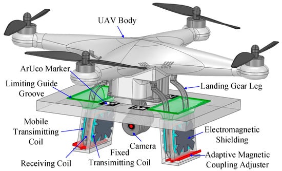
Figure 1.
Configuration of the proposed UAV wireless charging system.
Figure 1 illustrates the components of the wireless charging platform, including ArUco markers, a position-limiting guide groove, a gimbal camera protection recess, a magnetic coupler, and an electromagnetic shield. A protective concave space in the platform is designed to mitigate impacts during landing, ensuring the camera’s safety. The platform also incorporates ArUco markers to enable precise and stable UAV landing via visual guidance. The position-limiting guide groove features sloped edges that align with the UAV’s landing gear structure, reducing the requirement for ultra-precise landing and streamlining the process. The paper further explores various structural designs for the magnetic coupler and electromagnetic shielding, with detailed elaboration and analysis provided in subsequent sections.
The remainder of this paper is structured as follows: Section 2 presents the precise landing process, along with the design and analysis of the magnetic coupler. Section 3 focuses on the dimensional design of the electromagnetic shielding. Section 4 performs a theoretical analysis of the system circuit and constructs the corresponding experimental prototype. Finally, Section 5 summarizes the conclusions.
2. Design of UAV Wireless Charging System
2.1. Implementation of Autonomous Landing System
The precise autonomous landing of UAVs hinges on the accurate recognition and detection of specialized static cooperative markers. ArUco markers, renowned for their high efficiency in image thresholding, clear directional recognition, and excellent distinguishability of internal encoding, are highly regarded in applications involving pose estimation and camera calibration [,]. Their strong environmental adaptability, low cost, and ability to provide reliable identification and localization data under diverse lighting conditions make them indispensable for realizing effective and precise autonomous landing systems. ArUco markers also simplify system deployment and facilitate the establishment of versatile navigation configurations. During landing, UAVs accurately identify ArUco markers and perform refined pose estimation by extracting key feature points. Figure 2 shows a top view of the wireless charging platform, while Figure 3 provides a step-by-step illustration of the entire landing process.
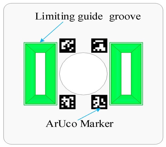
Figure 2.
Top view of wireless charging platform.
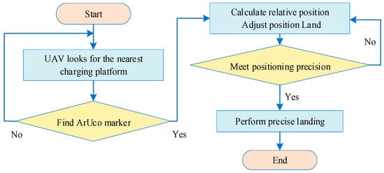
Figure 3.
UAV precise landing process.
Once the UAV-to-platform distance reaches the predetermined minimum threshold, the ArUco marker-based landing procedure is concluded, followed by UAV power-off and a subsequent free drop. In the event of landing misalignments, the UAV autonomously adjusts its position by leveraging its own weight in conjunction with guidance from the position-limiting guide groove, thereby achieving optimal coupling between the transmitting and receiving coils.
2.2. Dimensions Design of the Charging Coil
As research advances, magnetic couplers are now classified based on their magnetic flux distribution into two types: polarized and non-polarized magnetic pads. Nonetheless, since polarized magnetic pads require more materials than the latter, they lead to a significant increase in the overall weight of the charging system. Given the space constraints inherent in UAVs, non-polarized magnetic pads are the preferred option. Table 1 provides a comparison of parameters for several commonly used non-polarized magnetic pads. In magnetic couplers, circular coils generate uniform magnetic fields but occupy a relatively large area, while square coils produce concentrated magnetic fields yet suffer from edge effects.

Table 1.
Properties of popular coil structures.
2.3. Design of Proposed Magnetic Coupler
This paper has developed three distinct coil layout schemes to determine the optimal arrangement strategy for UAV wireless charging, which have been subjected to a comprehensive comparative analysis via ANSYS Electronics2021.R1(64bit) at a constant system operating frequency of 85 kHz.
After a UAV lands, the relative positional variation along the Z-axis (vertical orientation) is constrained and quasi-static, whereas the primary variability affecting coupling efficiency and transmission performance stems from alignment deviations within the X-Y planar dimension (two-dimensional space). Consequently, this paper focuses primarily on investigating the impact of positional relationships under two-dimensional conditions.
Figure 4 illustrates coil layout scheme A, where each receiving coil is paired with a dedicated single transmitting coil for charging. This design minimizes the air gap between the coils, thus achieving tight coupling, and boasts a larger magnetic flux capture area, ensuring high power transmission efficiency. The identical dimensions of the transmitting and receiving coils enable the maximum capture of the magnetic energy generated by the transmitting coil. Additionally, each coil is modeled as an equivalent ten-turn structure to ensure stable operation while reducing simulation time.
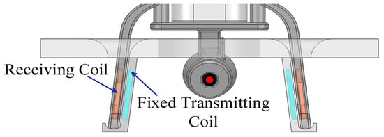
Figure 4.
Layout Scheme A.
As depicted in Figure 5, coil layout scheme B is designed to increase the wireless charging system’s charging speed by pairing each receiving coil with two fixed transmitting coils (i.e., Transmitting Coil A and Fixed Transmitting Coil B). The superposition of magnetic fields from these two coils generates a higher magnetic flux density at the receiving coil, which not only increases the transmitted power and improves the system’s charging efficiency but also accelerates the UAV’s charging process. However, sufficient space must be reserved for Fixed Transmitting Coil B to accommodate the UAV’s landing gear, thus increasing the air gap between this coil and the receiving coil. This enlarged air gap reduces the coupling coefficient and, in turn, degrades the power transfer efficiency.
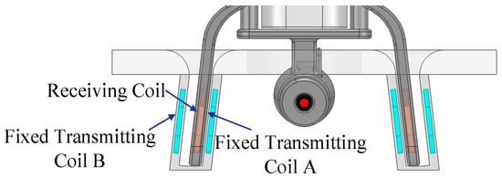
Figure 5.
Layout Scheme B.
In Layout Scheme C, an adaptive magnetic coupling adjuster is integrated into the position-limiting guide grooves, which functions similarly to a lever principle-based coil position regulator. This mechanism strategically positions the movable transmitting coil assembly at one extremity of the lever structure. Prior to UAV landing (as depicted in Figure 6a), the mobile transmitting coil is positioned at a relatively low initial position due to its intrinsic weight. When the UAV lands in the designated landing area, the mobile transmitting coil moves passively inward along the position-limiting guide grooves and finally reaches its predetermined optimal working position (as shown in Figure 6b). The resultant configuration establishes close proximity between the mobile transmitting coil and the receiving coil integrated within the landed UAV, thereby optimizing electromagnetic coupling efficiency.
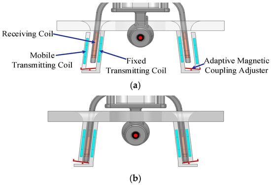
Figure 6.
Layout Scheme C: (a) landing; (b) complete landing.
The simulation results in Figure 7 provide detailed magnetic field distribution diagrams for schemes A, B, and C, along with their corresponding curves for magnetic flux density and specific values of induced currents. These visualizations effectively highlight the differences in magnetic field characteristics across the three schemes. Quantitative analysis of the magnetic field parameters reveals that Scheme B (Figure 7c) outperforms Scheme A (Figure 7a) in both magnetic field strength and distribution. Consequently, Scheme A was eliminated in the preliminary evaluation phase. Further detailed analysis indicates that the receiving coil current density is 6.4 for Scheme B, compared to 8.7 for Scheme C. Additionally, in terms of the uniformity of magnetic field strength distribution, Scheme C demonstrates a more uniform magnetic field profile than Scheme B.
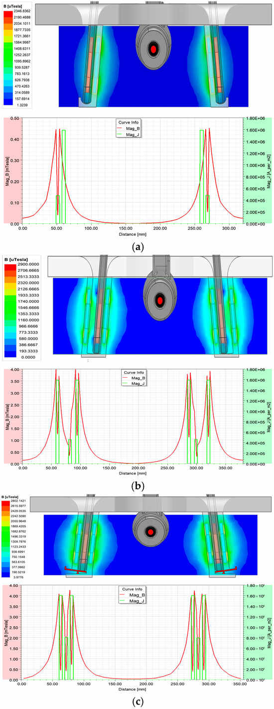
Figure 7.
Magnetic field distribution in the cross-section and current density: (a) single-sided fixed transmitting coil; (b) fixed transmitting coils A and B; (c) fixed transmitting coil and mobile transmitting coil.
In Table 2, the self-inductance of the transmitting coil is defined as . The fixed self-inductance of the transmitting coil is defined as , and its mutual inductance with the receiving coil is defined as . The self-inductance of the active transmitting coil is defined as , and its mutual inductance with the receiving coil is defined as . The parameters under different schemes are obtained in Table 2.

Table 2.
Properties of coils under different schemes (“-” MEANS NOT GIVEN).
It is obvious that scheme C has the superior performance. Specifically, the mutual inductance value between the mobile transmitting coil and the receiving coil in Scheme C is 5.98 , almost 80% higher than the mutual inductance of 3.32 in Scheme B. Therefore, this paper adopted Scheme C for the implementation in the wireless charging system, which ensures optimal system design and efficient energy transfer.
3. Dimensions Design of the Electromagnetic Shielding
3.1. Design of the Electromagnetic Shielding
In the design of wireless charging systems for UAVs, EMI from the surrounding environment and the alternating magnetic fields generated during the charging process pose a critical challenge []. Inadequate electromagnetic shielding not only can reduce the efficiency of the charging system, but also lead to electromagnetic leakage, which can severely disrupt the normal operation of the sensitive electronic components of the UAV. Therefore, to prevent electromagnetic interference and ensure the normal operation of the equipment, appropriate electromagnetic shielding measures play an irreplaceable role in the system design.
As shown in Table 3, parameters of several common electromagnetic shielding materials are compared. The selection of electromagnetic shielding materials and the design of the shielding layer require precise calculations and optimization to ensure that the EMI/EMC issues are minimized while considering economic feasibility.

Table 3.
Comparison of parameters of various magnetic shielding materials.
While ferrite pads are ideal for guiding high-frequency magnetic flux in wireless charging systems, their fragility renders them unsuitable for application on UAVs due to the risk of damage during landing. This paper, therefore, pairs manganese–zinc ferrite (a magnetic material) with the transmitting coil, as it is more cost-effective and performance-compatible than the two other common magnetic materials for the proposed wireless charging system. A preliminary analysis was conducted via ANSYS Maxwell simulation software, as depicted in Figure 8, to examine the magnetic coupler’s coupling coefficient and magnetic field distribution without electromagnetic shielding—establishing a performance baseline.
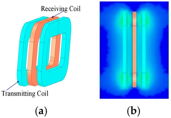
Figure 8.
No ferrite pad: (a) model of magnetic coupler; (b) magnetic field distribution in the cross-section.
This paper investigates how different electromagnetic shielding structures influence the performance of wireless charging systems. Simulations were run on square, grid, and cross-symmetrical structures—all featuring the same length and thickness yet distinct geometries—as described in Table 4. The analysis focused on their magnetic flux distribution. The results in Table 4 demonstrate that these structures efficiently direct the magnetic field to the working area. Figure 9 shows that the cross-symmetrical ferrite pad emerged as the optimal choice after evaluating the coupling coefficient, field containment, and material usage. It exhibits a slightly higher coupling coefficient than the square pad and significantly outperforms the grid-based design. Figure 9a indicates that this pad induces the strongest magnetic field at the receiving coil, thereby enhancing the system’s performance.

Table 4.
Comparison of electromagnetic shielding in popular shapes.
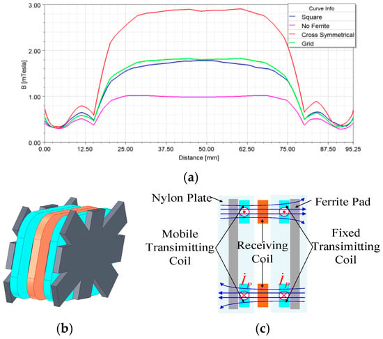
Figure 9.
(a) Magnetic field intensity at receiving coil when using different electromagnetic shielding; (b) Magnetic coupler with cross-symmetrical ferrite pad; (c) flux distribution on a cross section.
This paper quantifies the enhancement effect of the cross-symmetrical ferrite pad on wireless charging systems by introducing two fundamental parameters. The first, denoted as , is the coupling coefficient increase rate, which calculates the relative improvement in the coupling coefficient when a ferrite pad of a specific thickness is used compared to a system without electromagnetic shielding. This parameter provides insight into the direct impact of adding the ferrite pad on the coupling coefficient. The second parameter, denoted as , is the coupling coefficient gain, which reflects the effect of the thickness of the electromagnetic shielding material on the enhancement of the coupling coefficient. A higher value signifies a more substantial contribution of the electromagnetic shielding structure to the system’s overall performance improvement. Figure 10 shows that the thickness of the ferrite pad is defined as . The length, width, and diagonal of the ferrite pad are defined as , and , respectively. The length, width, and diagonal of the transmitting coil are defined as , and , respectively. Then, the commutation functions and are defined in the following:
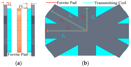
Figure 10.
Magnetic coupler with cross-symmetrical ferrite pad: (a) front elevation; (b) left elevation.
is the coupling coefficient of scheme C equipped with the ferrite pad. is the coupling coefficient of scheme C, which is equal to 0.465.
As shown in Figure 11, the relationship between , , and the thickness of the electromagnetic shielding structure can be observed. It is evident that the reaches its maximum value when the thickness of the electromagnetic shielding structure is 3 mm. Beyond this point, as increases, begins to decrease. Therefore, the proposed thickness for the electromagnetic shielding structure in the wireless charging system is determined to be 3 mm.
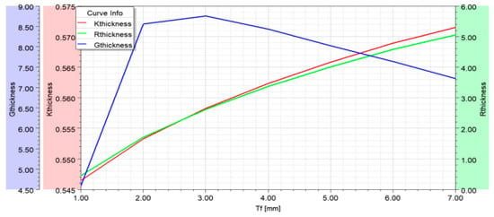
Figure 11.
Relationship between , , , and .
3.2. Electromagnetic Shielding Elongation Coefficient
Similarly, the influence of varying the extension distance of the electromagnetic shielding material beyond the transmitting coil’s outer contour on the coupling coefficient is systematically investigated. This paper defines the electromagnetic shielding elongation coefficient as
A comparison is made between the coupling coefficient of the electromagnetic shielding structure with different extension distances and the coupling coefficient of the transmitting coil without an electromagnetic shielding structure, with the coupling coefficient growth ratio being defined. Similarly, the amount of magnetic material used at different extension distances should be considered to reflect its effect on the coupling coefficient gain . The coupling coefficient growth ratio and the coupling coefficient gain are defined as
Figure 12 illustrates the correlation between parameters , , , and . It is evident that reaches its peak value when is 1.03. However, as continues to increase beyond this point, exhibits a decreasing trend.
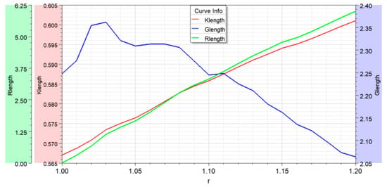
Figure 12.
The Relationship between , , , and .
3.3. Optimal Scheme
As a result of the above analysis, the overall scheme for the proposed wireless charging system was determined. When is equal to 3 mm and is equal to 1.03, such an electromagnetic shielding structure maximizes efficiency and economy. Using simulation under this condition, the following data were obtained: the coupling coefficient of the charging system is 0.562, the self-inductance of the transmitting coil is 20.6 , and the self-inductance of the receiving coil is 16.04 . Moreover, the mutual inductance between the transmitting and receiving coils is 10.21 . As depicted in Figure 13, the electromagnetic shielding structure significantly confines the magnetic field distribution generated by the transmitting coil, effectively localizing it within the charging area.
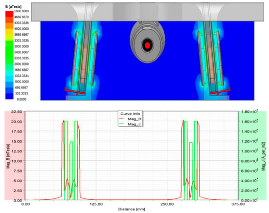
Figure 13.
The effect of the optimized electromagnetic shielding.
A comparison with Figure 7c reveals a substantial reduction in the leaked magnetic field strength from 4.8 to 0.68 , effectively mitigating the impact of electromagnetic interference on the UAV’s equipment. Furthermore, the inclusion of the electromagnetic shielding structure leads to an increase in the induced current density within the receiving coil from 8.03 to 11.24 .
4. Circuit Topology and Experiments
4.1. Circuit Topology
The proposed system’s circuit topology is shown in Figure 14. and represent the self-inductances of the two transmitting coils, respectively, and represents the self-inductance of the receiving coil. and represent the transmitting side’s compensation inductance and compensation capacitor, respectively. is the compensation capacitor on the receiving end. , , and are the mutual inductances between , , and , respectively. is the equivalent resistance of . is the total equivalent resistance of and . is the equivalent resistance of the receiving-end components (including and ). is the system’s operating frequency. is the DC voltage input to the inverter. is the load resistance. is the circuit output voltage.
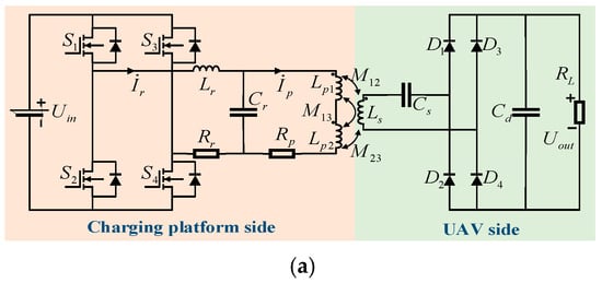
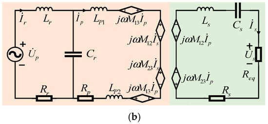
Figure 14.
Circuit block diagram: (a) circuit topology; (b) equivalent circuit.
According to Kirchhoff’s voltage law and mutual coupling theory, the relationship between the current and voltage at the transmitter and receiver is expressed as
To achieve a purely resistive characteristic after circuit resonance and improve the stability of the wireless charging system, the circuit angular frequency is expressed as
Substituting Equation (5) into Equation (4), , and are obtained as
According to Equation (6), the input and output power and efficiency of the system are calculated using Equation (7). Equation (7) reveals that is mainly affected by , , and . During the charging process of the UAV’s power lithium battery, the internal resistance only varies within the range of milliohms, which has a limited impact on system efficiency. In this paper, the wireless charging system angular frequency is fixed at 85 kHz. Consequently, the significant mutual inductance effect, caused by the misalignment between the transmitting and receiving coils, adversely affects the performance of the wireless charging system. Therefore, the mutual inductance between coils is the primary factor that influences the efficiency of the charging system. Substituting the relevant circuit parameters, listed in Table 5, into Equations (6) and (7), the theoretical analysis shows that the is 96.03%.

Table 5.
Parameters of the wireless charging system.
4.2. Experiment Results
To demonstrate the charging performance of the proposed system, an experimental prototype test platform is constructed using the data shown in Table 5, as illustrated in Figure 15. The system operates at a fixed frequency of 85 kHz. The primary side inverter uses SiC MOSFET C2M0080120D (Wolfspeed, Durham, NC, USA), and the secondary side rectifier uses Schottky diodes DST1045S (Littelfuse Inc., Chicago, IL, USA). Both the transmitting and receiving coils are wound with Litz wire of 0.07 mm × 1000 specifications. The weight of the receiving coil is 54.8 g. Additionally, the magnetic shielding layer employs PC40 ferrite material from TDK (Tokyo, Japan).
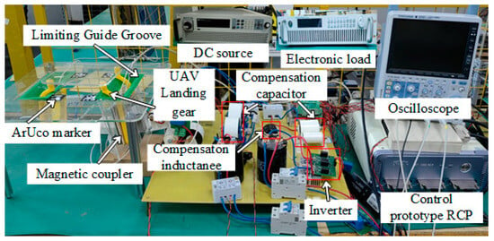
Figure 15.
Experiment setup of wireless charging system.
As shown in Figure 16a,b, the output voltage and current of the inverter and the input voltage and current of the rectifier, respectively, are nearly in phase with each other. Figure 16c shows a charging current of 4.56 A and a charging voltage of 17.3 V, which meets the design requirements of the system. Further analysis of system losses at the rated power load, as shown in Figure 16d, reveals that the losses primarily consist of three parts: inverter loss, magnetic coupler loss, and rectifier loss. The efficiency of each part is , , and , respectively. Based on this observation, the efficiency of the magnetic coupling component closely matches the theoretical analysis. The main cause of system losses is focused on the inverter and rectifier sections, primarily due to the significant conduction losses from the rectifier diodes utilized in the experimental setup. Inverter losses can be further reduced in the future by optimizing the drive circuit, while rectifier losses are limited by the voltage drop of Schottky diodes. Selecting Schottky diodes with a smaller voltage drop can also improve system efficiency.
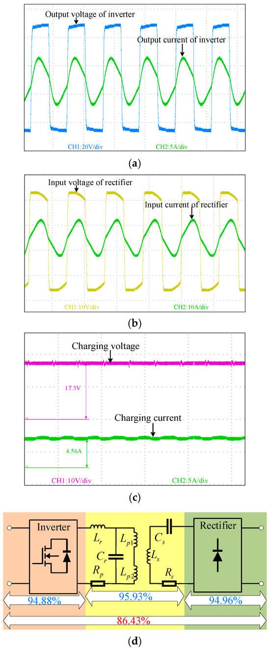
Figure 16.
Power transfer ability test: (a) inverter output waveform; (b) rectifier input waveform; (c) charging voltage and charging current; (d) system loss analysis.
To highlight the differences and advantages of the proposed wireless charging system over existing systems, a detailed comparison is presented in Table 6.

Table 6.
Comparison with previous works (“-” MEANS NOT GIVEN).
The results show that the proposed system enables precise autonomous UAV landing and tightly coupled wireless power transfer without the need for position correction devices [] or additional sensing components [], resulting in a more cost-effective solution. Furthermore, the proposed planar magnetic coupler exhibits lower EMI and is easier to install compared to the planar magnetic couplers in [,]. In particular, the proposed magnetic coupler (equipped with the adaptive adjuster) can use the UAV’s own weight to adjust the transmission coil position, which significantly improves the performance compared to other coupler types. The proposed system is not only suitable for automatic charging of inspection UAVs, but also adaptable to high-power applications. Two parallel, non-interfering subsystems (each integrating a receiver coil on the UAV’s landing gear) can be implemented to increase charging power, optimize heat dissipation, and balance the UAV’s weight distribution. The compact size of the proposed magnetic coupler and the confined operating range of the magnetic field minimize mutual coupling between the subsystems, ensuring the scalability and applicability of the design.
5. Conclusions
This paper presents a lightweight, low magnetic leakage interference, high-efficiency, and tightly coupled wireless charging system suitable for inspection UAVs. A low-cost, high-precision alignment mechanism for the magnetic coupling structure is achieved by innovatively integrating ArUco markers with position-limiting guide grooves. Through simulation and experimental validation, the designed dual-transmitting-coil structure combined with the adaptive magnetic coupling adjuster is verified to effectively utilize the UAV’s self-weight to enhance coupling strength. This novel approach nearly doubles the coupling coefficient, thereby achieving a notable system efficiency of 93.3%. Furthermore, the integration of magnetic shielding is demonstrated to further boost the magnetic coupler’s efficiency to an impressive 95.93%. This research provides a compelling and practical solution for improving the operational efficiency of UAVs via a cost-effective, high-performance wireless charging system, and confirms that the proposed system is expected to be further applicable to unattended UAV charging in the future.
Author Contributions
Methodology, Y.C. and X.Z.; Software, R.Z. and S.Y. (Shaojie Yu); Formal analysis, P.L. and S.Y. (Shuairan Yu). All authors have read and agreed to the published version of the manuscript.
Funding
The paper was supported by the Jilin Provincial Department of Science and Technology under grant 20250102141JC.
Data Availability Statement
Data is contained within the article.
Acknowledgments
We acknowledge any technical support from the Beihua University Research and Innovation Project for Graduate Students under grant [2024]016.
Conflicts of Interest
The authors declare no conflicts of interest.
References
- Nawaz, H.; Ali, H.M.; Massan, S.U.R. Applications of unmanned aerial vehicles: A review. 3C Tecnol. 2019, 85–105. [Google Scholar] [CrossRef]
- Seuken, S.; Friedrich, P.; Dierks, L. Market design for drone traffic management. In Proceedings of the AAAI Conference on Artificial Intelligence 2022, Virtually, 22 February–1 March 2022; Volume 36, pp. 12294–12300. [Google Scholar]
- Mohsan, S.A.H.; Othman, N.Q.H.; Khan, M.A.; Amjad, H.; Żywiołek, J. A comprehensive review of micro UAV charging techniques. Micromachines 2022, 13, 977. [Google Scholar] [CrossRef]
- Danciu, M.C.; Yingta, N.; Rehman, I.U.; Aleshaiker, S. UAV Automated Charging Station and Charging Network in Smart Cities for Telemedicine Delivery. In Proceedings of the 2023 IEEE International Smart Cities Conference (ISC2), Bucharest, Romania, 24–27 September 2023; pp. 1–6. [Google Scholar]
- Li, Y.; Liu, S.; Zhu, X.; Hu, J.; Zhang, M.; Mai, R.; He, Z. Extension of ZVS Region of Series–Series WPT Systems by an Auxiliary Variable Inductor for Improving Efficiency. IEEE Trans. Power Electron. 2021, 36, 7513–7525. [Google Scholar] [CrossRef]
- Vishnuram, P.; Panchanathan, S.; Rajamanickam, N.; Krishnasamy, V.; Bajaj, M.; Piecha, M.; Blazek, V.; Prokop, L. Review of Wireless Charging System: Magnetic Materials, Coil Configurations, Challenges, and Future Perspectives. Energies 2023, 16, 4020. [Google Scholar] [CrossRef]
- Cai, C.; Saeedifard, M.; Wang, J.; Zhang, P.; Zhao, J.; Hong, Y. A Cost-Effective Segmented Dynamic Wireless Charging System With Stable Efficiency and Output Power. IEEE Trans. Power Electron. 2022, 37, 8682–8700. [Google Scholar] [CrossRef]
- Le, Q.; Wu, R.; Chen, J.; Huang, M.; Fu, Y.; Huang, F.; Wang, L.; Du, S.; Li, Q. Wireless Power Transmission System for Vehicle Based on Multi-Transmitter Coils Array. IEEE Access 2023, 11, 82784–82793. [Google Scholar] [CrossRef]
- Cai, C.; Wang, J.; Zhang, F.; Liu, X. A Multichannel Wireless UAV Charging System with Compact Receivers for Improving Transmission Stability and Capacity. IEEE Syst. J. 2022, 16, 997–1008. [Google Scholar] [CrossRef]
- Yazdi, S.S.H.; Shafiei, S.; Kapanov, A.; Shakhin, Y.; Namadmalan, A.; Zollanvari, A.; Bagheri, M. A Wireless Charging System Based on a DR-IPT to Power a UAV From Distribution Poles. IEEE Trans. Ind. Appl. 2023, 59, 7757–7770. [Google Scholar] [CrossRef]
- Zhai, X.; Wang, H.; Li, J.; Huang, Z.; Gao, R. A wireless charging method with lightweight pick-up structure for UAVs. Electr. Eng. 2021, 103, 2847–2854. [Google Scholar] [CrossRef]
- Hassan, E.S.; Jabbari, A.; Alharbi, A.A. Smart Irrigation Enhancement Through UAV-Based Clustering and Wireless Charging in Wireless Sensor Networks. Drones 2025, 9, 253. [Google Scholar] [CrossRef]
- Iob, F.; Segatti, G.; Stefánsson, T.; Gelati, F.; Bernacchia, G.; Saggini, S. A Novel Lightweight Wireless Charging System for UAV Applications. In Proceedings of the 2024 IEEE Applied Power Electronics Conference and Exposition (APEC), Long Beach, CA, USA, 25–29 February 2024; pp. 279–283. [Google Scholar]
- Wu, S.; Cai, C.; Jiang, L.; Li, J.; Yang, S. Unmanned Aerial Vehicle Wireless Charging System with Orthogonal Magnetic Structure and Position Correction Aid Device. IEEE Trans. Power Electron. 2021, 36, 7564–7575. [Google Scholar] [CrossRef]
- Arteaga, J.M.; Aldhaher, S.; Kkelis, G.; Kwan, C.; Yates, D.C.; Mitcheson, P.D. Dynamic Capabilities of Multi-MHz Inductive Power Transfer Systems Demonstrated with Batteryless Drones. IEEE Trans. Power Electron. 2019, 34, 5093–5104. [Google Scholar] [CrossRef]
- Feng, T.; Zuo, Z.; Sun, Y.; Dai, X.; Wu, X.; Zhu, L. A Reticulated Planar Transmitter Using a Three-Dimensional Rotating Magnetic Field for Free-Positioning Omnidirectional Wireless Power Transfer. IEEE Trans. Power Electron. 2022, 37, 9999–10015. [Google Scholar] [CrossRef]
- Venkatesan, M.; Rajamanickam, N.; Vishnuram, P.; Bajaj, M.; Blazek, V.; Prokop, L.; Misak, S. A review of compensation topologies and control techniques of bidirectional wireless power transfer systems for electric vehicle applications. Energies 2022, 15, 7816. [Google Scholar] [CrossRef]
- Manivannan, B.; Kathirvelu, P.; Balasubramanian, R. A review on wireless charging methods—The prospects for future charging of EV. Renew. Energy Focus 2023, 46, 68–87. [Google Scholar] [CrossRef]
- Triviño, A.; Gonzalez-Gonzalez, J.M.; Castilla, M. Review on control techniques for EV bidirectional wireless chargers. Electronics 2021, 10, 1905. [Google Scholar] [CrossRef]
- Zhang, Y.; Yan, Z.; Liang, Z.; Li, S.; Mi, C.C. A High-Power Wireless Charging System Using LCL- N Topology to Achieve a Compact and Low-Cost Receiver. IEEE Trans. Power Electron. 2020, 35, 131–137. [Google Scholar] [CrossRef]
- Li, Y.; Sun, W.; Liu, J.; Liu, Y.; Yang, X.; Li, Y.; Hu, J.; He, Z. A New Magnetic Coupler with High Rotational Misalignment Tolerance for Unmanned Aerial Vehicles Wireless Charging. IEEE Trans. Power Electron. 2022, 37, 12986–12991. [Google Scholar] [CrossRef]
- Duan, S.; Lu, X.; Wu, H.; Zhang, H.; Zhang, Z.; Wang, G. Unmanned Aerial Vehicle Wireless Power Transfer System for Long-Distance Transmission Line Patrol. In Proceedings of the 2022 IEEE International Power Electronics and Application Conference and Exposition (PEAC), Guangzhou, China, 4–7 November 2022; pp. 1324–1329. [Google Scholar]
- Wang, J.; Chen, R.; Cai, C.; Zhang, J.; Wang, C. An Onboard Magnetic Integration-Based WPT System for UAV Misalignment-Tolerant Charging With Constant Current Output. IEEE Trans. Transp. Electrif. 2023, 9, 1973–1984. [Google Scholar] [CrossRef]
- Pahlavan, S.; Shooshtari, M.; Jafarabadi Ashtiani, S. Star-shaped coils in the transmitter array for receiver rotation tolerance in free-moving wireless power transfer applications. Energies 2022, 15, 8643. [Google Scholar] [CrossRef]
- Ağçal, A.; Doğan, T.H. A Novel Folding Wireless Charging Station Design for Drones. Drones 2024, 8, 289. [Google Scholar] [CrossRef]
- Obayashi, S.; Kanekiyo, Y.; Sugaki, K.; Watabe, A.; Nakakoji, H.; Ichikawa, H.; Takao, N. 750-W 85-kHz Inductive Rapid Charging System for Mid-sized UAV. In Proceedings of the 2022 IEEE Wireless Power Week (WPW), Bordeaux, France, 5–8 July 2022; pp. 605–609. [Google Scholar]
- Gwon, G.-J.; Kwon, Y. Enhancement of Wireless Power Transmission Efficiency and Flexibility via an Optimized Three-Dimensional Coupled Magnetic Resonance System with Double Transmitter Coil. J. Electr. Eng. Technol. 2021, 16, 1415–1426. [Google Scholar] [CrossRef]
- Marut, A.; Wojciechowski, P.; Wojtowicz, K.; Falkowski, K. Visual-based landing system of a multirotor UAV in GNSS denied environment. In Proceedings of the 2023 IEEE 10th International Workshop on Metrology for AeroSpace (MetroAeroSpace), Milan, Italy, 19–21 June 2023; pp. 308–313. [Google Scholar]
- He, Y.; Gao, Z.T. Autonomous and Precise Landing of UAVs Based on Vision Navigation. Electron. Opt. Control 2023, 30, 88–93. [Google Scholar]
- Jie, H.; Zhao, Z.; Zeng, Y.; Chang, Y.; Fan, F.; Wang, C.; See, K.Y. A review of intentional electromagnetic interference in power electronics: Conducted and radiated susceptibility. IET Power Electron. 2024, 17, 1487–1506. [Google Scholar] [CrossRef]
Disclaimer/Publisher’s Note: The statements, opinions and data contained in all publications are solely those of the individual author(s) and contributor(s) and not of MDPI and/or the editor(s). MDPI and/or the editor(s) disclaim responsibility for any injury to people or property resulting from any ideas, methods, instructions or products referred to in the content. |
© 2025 by the authors. Licensee MDPI, Basel, Switzerland. This article is an open access article distributed under the terms and conditions of the Creative Commons Attribution (CC BY) license (https://creativecommons.org/licenses/by/4.0/).