Abstract
This paper presents the design, construction, and tests of a polarization-reconfigurable phased array antenna. The proposed array allows the polarization at the main lobe maximum direction to be electronically reconfigured between right-hand (RHCP) and left-hand circular polarization (LHCP). Single-fed microstrip antennas, each with four tunable varicap diodes, are employed in the phased array to achieve a low axial ratio (AR) at the steering angles. Special attention is given to the microstrip antenna design and varicap modeling, which involves the use of measured data and search algorithms running in an electromagnetic/circuit co-simulation environment. To illustrate the proposed approach, a six-element linear phased array at 2.2 GHz has been built and tested in an anechoic chamber. The experimental results demonstrate an AR below 1 dB in both RHCP and LHCP states over a wide range of steering angles, and even in a multibeam configuration, validating our design method.
1. Introduction
The phased array antenna has been an important research area of microwave engineering since the 1960s [1], mainly due to its usefulness in a wide variety of relevant applications, such as military systems [1], imaging [2,3], communications [4,5], medicine [6,7], and radar [8,9,10]. Fundamentally, a phased array is composed of a set of identical radiators, spatially distributed, with their relative excitations (amplitudes and phases) independently controlled via a beamformer circuit [11,12]. Relevant radiation features can be achieved by appropriately changing these excitations, for example, main beam and null steering [13,14], pattern shaping [15,16], and multibeam configuration [17,18]. More recently, special attention has been devoted to the phased arrays composed of reconfigurable antennas due to their ability to handle the fast parameter changes of many modern electronic systems [19,20].
In the literature, reconfigurable antennas are typically classified into four main groups according to the controlled parameter: frequency, radiation pattern, polarization, or combinations of these parameters [21,22]. Frequency reconfigurability, for example, can be attained by changing the radiator’s electrical length or by loading electronically controlled reactive components [23]. Consequently, the band of operation can be switched, or the impedance bandwidth can even be varied from wideband to narrowband, incorporating the functionality of a dynamic filter in the antenna. This feature is particularly useful in multiband systems [24], cognitive radios [25], and GNSS [23,26].
The pattern reconfigurability, in turn, allows the control of the main beam direction or the radiation pattern shape [27,28]. Phased arrays composed of pattern-reconfigurable radiators can offer a wider range of beam scanning angles with lower gain fluctuation during the scanning compared to conventional phased arrays of the same geometry [29,30]. Numerous applications have benefited from these characteristics, such as WLAN communication [27], 5G systems [31], MIMO systems [32], and wearable antennas for body-centric wireless communications [33].
The third group of reconfigurable radiators, and the focus of this work, encompasses polarization-reconfigurable antennas [34,35,36,37]. These antennas offer a means to reduce multipath interference and polarization mismatch, thereby enhancing the performance of electronic countermeasure systems and transmitarray systems [38]. Their adaptability is particularly advantageous for satellite [39] and mobile [40] communications. For this reason, considerable efforts have been devoted to the development of radiators capable of switching between right-hand (RHCP) and left-hand circular polarization (LHCP) or between two orthogonal linear polarizations.
The fourth group comprises compound reconfigurable antennas, which can simultaneously reconfigure multiple parameters. These antennas can have reconfigurable features between frequency and pattern [41,42], frequency and polarization [43,44], frequency, pattern, and polarization [45,46], and pattern and polarization [47,48,49]. Some technologies are reported in the literature to achieve reconfigurability, and they can be classified into four categories [21]: (i) mechanically movable parts [47,50,51]; (ii) tunable materials [44]; (iii) microelectromechanical switches (MEMS) [52,53]; and (iv) semiconductor switches. Techniques based on semiconductor switches involve components such as p-i-n diode [23,24,25,31,42], field-effect transistor (FET) [54,55], or varactor diode [56,57]. The varactor diode, the solution adopted in this article, works as a continuously voltage-controlled low-loss capacitance, making it well-suited for antenna tuning [56].
Reconfiguring the polarization of phased array antennas is a challenging task that has recently gained attention in the research community [57,58,59,60,61]. A hybrid design approach is proposed in [57], which enables polarization reconfiguration (RHCP/LHCP) and continuous beam scanning up to nearly off the boresight. To accomplish this objective, p-i-n diodes and varactors are employed in the four-port antenna elements, and phase shifters are used to feed them.
In [58], an phased array is presented, comprising two-port radiators with parasitic patches and featuring a 6-bit phase control beamforming. This configuration allows for the selection between linear, LHCP, and RHCP polarizations. Additionally, Ref. [59] introduces a multiport beamforming system based on a reconfigurable waveguide phased antenna array for satellite communication applications. The antenna, fed by a microstrip single-layer multiport feeding network, enables the reconfiguration of polarization between linear, LHCP, and RHCP in the K/Ka bands. By using the spatial phase shift technique, Ref. [60] proposes a patch array antenna with reconfigurable polarizations. In the developed solution, the main beam can be dynamically steered in nine directions, and the radiator is manufactured in a four-layer structure and owns three switchable feeding probes.
Note that the solutions outlined in [57,58,59,60] achieve a circularly polarized (CP) steered main beam with an axial ratio (AR) better than 3 dB through multiport antennas. In contrast, Ref. [61] introduces a polarization-reconfigurable linear phased array composed of single-fed microstrip antennas with p-i-n diodes that commute between RHCP and LHCP. However, the optimization of this phased array was focused on ensuring a low AR only at broadside; i.e., the AR at the main lobe maximum is degraded as the steering angle is increased, as illustrated in Figure 1 and confirmed by both the theoretical and experimental results shown in [61]. We see in Figure 1 that the AR remains below 3 dB only for main beam pointing angles in the range of to if the two CP states are considered.
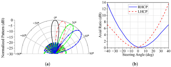
Figure 1.
Circularly polarized phased array. (a) Steering the main lobe. (b) Axial ratio at the main lobe maximum versus the steering angle.
In this paper, we present the design of a reconfigurable circularly polarized phased array antenna in which both the polarization sense and AR can be controlled as the main beam is steered. The array is formed by single-fed microstrip antennas with truncated corners, similar to those described in [61,62,63], but with the p-i-n diodes replaced by varicap diodes. The main idea is to use the continuous variation of the equivalent capacitance of the varicaps to change the sense of polarization and to fine-tune the AR, which cannot be accomplished with p-i-n diodes. Consequently, the AR at the main beam maximum is not degraded and remains close to 0 dB for all pointing angles. In addition to the theoretical procedure for designing the antenna and the array, a comprehensive experimental validation was also conducted. The obtained results demonstrate an excellent agreement between the measured input impedance and radiation pattern of the antenna and the corresponding full-wave simulations. A similar consistency is observed for the phased array, where the synthesized radiation patterns closely match the simulated ones, confirming the axial ratio reconfigurability both for main-beam steering and for the dual-beam configuration.
As for the main novelties of this article, they can be summarized in the following points: (a) the design of a microstrip antenna with truncated corners loaded with four varicap diodes that allow for controlling both the sense of polarization and AR level; (b) a method for extracting the electrical model of the varicap diode placed in the antenna. This approach leads to an accurate estimation of the control voltages that effectively adjust the AR in a specific direction; and (c) the design and tests of a reconfigurable circularly polarized phased array with electronic control of the sense of polarization and AR at the main beam maximum, including the synthesis of multibeam patterns, in which excellent AR is achieved for all beams.
The rest of this article is organized as follows. Section 2.1 presents the procedure to model the varicap diodes, Section 2.2 describes the design of the polarization-reconfigurable microstrip antenna, and Section 2.3 summarizes the results obtained with the antenna prototype. In Section 3.1, we proceed with the design and optimization of a six-element linear array that exhibits a low reflection coefficient and a low AR for a wide range of steering angles, as well as for multibeam patterns. The array is then integrated with a microwave beamformer [64], and tests are performed in an anechoic chamber to illustrate the capability of steering the main lobe with RHCP or LHCP maintaining excellent levels for the AR, as reported in Section 3.2. Finally, some conclusions are drawn in Section 4.
2. Antenna Design
The geometry of the phased array element is derived from the well-known circularly polarized microstrip antenna with truncated corners [65]. This radiator allows the polarization to change between RHCP and LHCP when its corners are appropriately connected to the trimmed patch by switches, as detailed in [62,63]. In this paper, the varicap diode is selected to work as a switch instead of the commonly used p-i-n diode [62,63], making it possible to fine-control the AR in addition to changing the polarization sense. To carry out the antenna design, the varicap diode is first modeled from the measurement of its reflection coefficient. Next, a theoretical design of the reconfigurable antenna, which accounts for the diode model, is realized in Ansys HFSS. After that, a prototype is built, and from its measured input impedance, we extract a refined model of the diode integrated with the antenna.
2.1. Diode Characterization
Since the phased array of this article must operate at 2.2 GHz, we chose the BB833 varicap diode from Infineon Technologies, which works up to 2.5 GHz. This diode was first characterized through the reflection coefficient method [66] using an Agilent PNA-L N5230A vector network analyzer. The diode cathode was soldered at the end of a 50 microstrip line on a substrate with a relative permittivity of 2.55, a loss tangent of 0.0022, and a thickness of 1.524 mm, and the diode anode was grounded, according to Figure 2a. The reverse bias voltage was applied through an HP 11612A bias tee and varied from 0 to 25 V (at 12 non-uniformly spaced samples). The circuit board also has a short-circuited microstrip line (ref. line), serving to adjust the measurement reference plane.
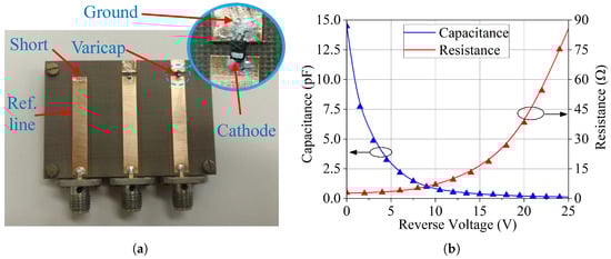
Figure 2.
Varicap diode modeling. (a) Test board. (b) c and r fitted curves.
Under the assumption of narrowband operation, the diode can be modeled as an RC series circuit, with resistance and capacitance as functions of the applied DC voltage. We measured the diode input impedance at 2.2 GHz for the set of 12 voltages above and computed the corresponding resistances and capacitances. Then, we applied curve fitting using Wolfram Mathematica to derive expressions for the capacitance, c, and resistance, r, in terms of the reverse bias voltage, V:
with V in volts. Figure 2b shows the plots of c and r as a function of V (solid lines), together with the points obtained from the measured data (symbols). As expected, the capacitance decreases and the resistance increases as the reverse voltage is increased.
It is important to note that the parameters extracted from the device under test do not perfectly match the actual behavior of the component when mounted in the antenna, mainly due to differences between the antenna and the test board microstrip line geometries. Additionally, the varicap exhibits a series inductance that was omitted in this initial model, since the RC parameters are sufficient for the preliminary design of the antenna for narrowband operation around 2.2 GHz. This simplified model allows an initial evaluation of how the antenna performance varies with the varicap capacitance as the reverse voltage is swept from 0 V to 25 V. The small inaccuracies introduced via this first model can easily be compensated for by adjusting the diode bias voltage, as will be discussed in the next section. There, an improved RLC series model is derived to better account for the diode’s frequency response, including, for example, the effects of the mounting characteristics of the component.
The RC series circuit, representing the varicap diode model, can be incorporated into the HFSS simulation through three distinct methods: (I) electromagnetic/circuit co-simulation; (II) lumped RLC boundary condition; and (III) lumped port, in which the capacitance and resistance are declared in the renormalization impedance field. All three methods yield comparable results, and the last two (II and III) can be seamlessly implemented in the electromagnetic simulation environment. For the simplicity of implementation and the convenience of post-processing, this work adopts the third method. By introducing (1) and (2) into the renormalization impedance field, parametric analyses concerning the varicap response can be rapidly conducted, requiring only a single electromagnetic simulation run.
2.2. Antenna Design
After modeling the diode, the antenna design is executed using Ansys HFSS software. The antenna geometry is depicted in Figure 3, and it is printed on a square dielectric substrate of relative permittivity, , the loss tangent tan , thickness, h, and the size, . As can be seen, the antenna is composed of a rectangular patch (dimensions L and W) with four truncated corners. These corners are connected to four isosceles right triangles with legs of length a, incorporating the varicap diodes. The bias voltages are applied to the diodes through four metalized via holes connected to the right triangles via LMCI2012 15 nH inductors (RF chokes). These inductors have a self-resonant frequency around 2 GHz. Also, the patch is short-circuited at its center with a metalized via hole to ground the varicap anode. This via hole has little effect on the antenna performance since the electric field in the substrate is null at the center position for the two orthogonal modes excited at the operating frequency. It is worth mentioning that the patch is rectangular (rather than square) to compensate for the probe inductance, resulting in a symmetrical reflection coefficient curve [62,67]. In addition, all elements of the bias circuit are included in the full-wave simulation to improve the accuracy of the results.
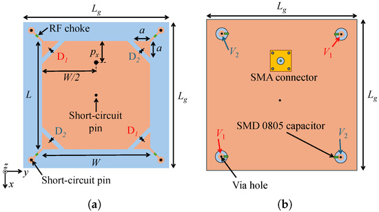
Figure 3.
Antenna geometry. (a) Top view. (b) Bottom view.
At this stage, assuming that the pairs of diodes D1 and D2 are reverse-biased with DC voltages and , respectively, the antenna is optimized to minimize the broadside AR at 2.2 GHz. We impose that the pairs D1 and D2 operate with capacitances of 10 pF and 2 pF, respectively, to achieve RHCP performance, which represents the design condition adopted for dimensioning the radiator. Starting from these values allows us to change the reactances of the diodes significantly during the antenna operation since the BB833 capacitance ranges from approximately 0.1 to 15 pF at 2.2 GHz, as shown in Figure 2b. The dimensions obtained after the optimization are as follows: mm, mm, mm, and mm, for a dielectric substrate with , , mm, and mm. The corresponding input impedance and broadside AR versus frequency are presented in Figure 4, where we verify that the antenna is well matched to a 50 SMA connector and radiates circular polarization at 2.2 GHz. To achieve LHCP performance, we can interchange the capacitances of the pairs of diodes, i.e., D1 with 2 pF and D2 with 10 pF.
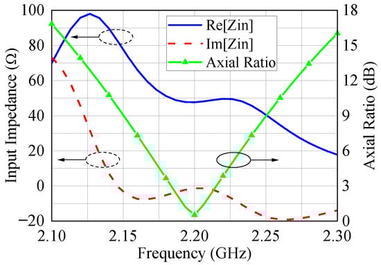
Figure 4.
Input impedance and broadside AR of the designed antenna.
With the synthesized antenna, we analyze the angular axial ratio at 2.2 GHz as a function of the diode capacitance. The capacitances of the D2 diodes are kept fixed at 2 pF, while the capacitances of the D1 diodes are varied around 10 pF (ranging from 9 to 11 pF). The result of this process is the steering of the direction of the minimum AR, as illustrated in Figure 5. This occurs because the capacitance change modifies the surface current on the patch and, consequently, the radiated electric field. This behavior is of fundamental importance for tuning the AR of the phased array comprising this antenna.
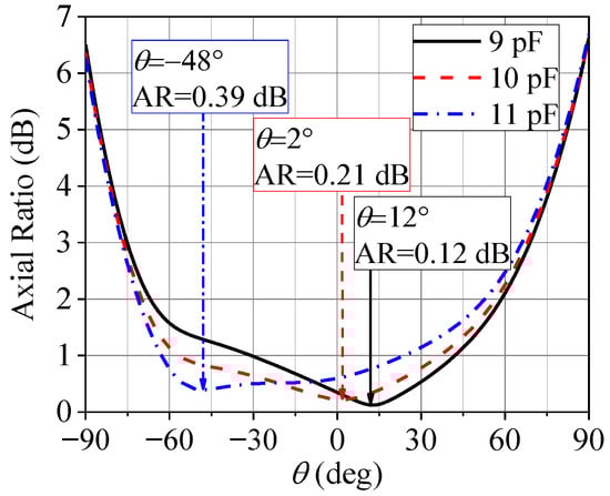
Figure 5.
Angular AR (-plane) at 2.2 GHz of the designed antenna for different capacitances of the D1 diodes and capacitances of the D2 diodes fixed at 2 pF.
2.3. Element Prototype and Experimental Results
To validate our design, a prototype, shown in Figure 6, was manufactured and tested in our laboratory. Initially, we conducted two measurement sets to characterize the inductors and diodes. In the first set, resistors (SMD 0805) were soldered in place of the intended varicap diodes, while the 15 nH inductors were accurately soldered in their designated locations. Next, the antenna input impedance was measured with a vector network analyzer (Figure 7a). By using the HFSS optimization tool, the effective inductances of the inductors were computed to match the theoretical impedance with the experimental one (Figure 7a), as listed in Figure 7b. The dispersive behavior of the inductor observed in Figure 7b is expected for operation in the vicinity of resonance [68], emphasizing the importance of component characterization.
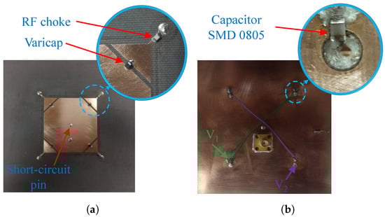
Figure 6.
Antenna prototype. (a) Top view. (b) Bottom view.

Figure 7.
Measurement without the varicap diodes. (a) Input impedance. (b) Effective inductances of the RF chokes.
In the second set, the 0 resistors were replaced with the varicap diodes, and the antenna input impedance was measured for seven combinations of and . For each voltage pair (, ), the HFSS optimization tool was employed to find the inductance, capacitances, and resistances of the diodes’ RLC series models that match the theoretical impedance with the measured data. Figure 8 shows four examples of measured impedances and the respective fitted responses plotted on the Smith chart from 2.1 to 2.3 GHz. As can be seen, the HFSS curves agree well with the experimental ones. The corresponding capacitances and resistances of these four configurations are listed in Table 1. The series inductance, L, of the model was estimated to be 0.6 nH and is not a function of the reverse voltage since it is primarily due to the component leads. It is relevant to note that the varicap diodes have a significant impact on the reflection coefficient, as illustrated in Figure 8. Therefore, the design optimization was carried out to ensure that, at 2.2 GHz for both RHCP and LHCP states, the reflection coefficient remains as low as possible.
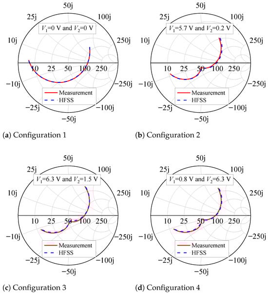
Figure 8.
Measured input impedance and simulated fitted curves.

Table 1.
Parameters of the diode equivalent RLC series circuit.
Based on the preceding analysis, we derive an accurate RLC series model for the diode. Using the curve fitting capabilities of Wolfram Mathematica, we obtain expressions (3) and (4) for the resistance, R, and capacitance, C, of the equivalent circuit as functions of the reverse DC bias voltage, V, in volts. These equations are valid for reverse voltages in the range of 0 to 8 V and are plotted in Figure 9 (solid lines) together with the resistances and capacitances extracted from the curve fittings conducted in HFSS (symbols). Considering other voltage pairs, different from the seven mentioned earlier but still within the range of 0 V to 8 V, we measured the antenna input impedance and compared it with the impedance computed in HFSS using (3) and (4). Good agreement, similar to that observed in Figure 8, was achieved, validating the proposed modeling strategy for the varicap.
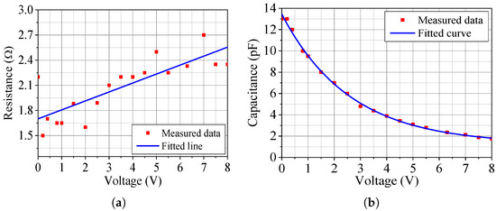
Figure 9.
Parameters of the improved diode model. (a) Resistance. (b) Capacitance.
To map the broadside AR and reflection coefficient responses of the designed radiator as functions of any combination of and in the range of 0 to 8 V, a post-processing analysis of the antenna is conducted in HFSS at 2.2 GHz, considering (3) and (4). Figure 10 shows the resulting level curves of the broadside AR and reflection coefficient. It is evident that both polarization sense and AR level can be tuned, with good impedance matching achieved under conditions of circular polarization.
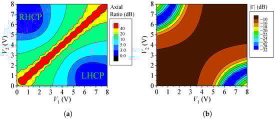
Figure 10.
Antenna responses at 2.2 GHz. (a) Broadside AR. (b) Reflection coefficient.
The validation of this study involves measuring the reflection coefficient and AR at broadside in the anechoic chamber for six combinations of and , as listed in Table 2 and Table 3, at 2.2 GHz. Except for configurations 3 and 4, in which the antenna is LHCP and RHCP at broadside, respectively, the other configurations were selected randomly. Table 2 presents the theoretical predictions of the AR together with the measured results, showing, in the worst case, a small deviation of 14.8%. Similarly, the reflection coefficient, detailed in Table 3, demonstrates very good agreement between the experimental and theoretical results. In this work, we employed the polarization-pattern method to measure the AR in a specific direction.
Table 2.
Comparison between experimental and theoretical AR at 2.2 GHz.
Table 3.
Comparison between experimental and theoretical reflection coefficients at 2.2 GHz.
The frequency responses of the AR at broadside for configurations 2 and 3 are depicted in Figure 11. In particular, for configuration 3, an experimental fine-tuning of just 0.2 V was applied to and to achieve a low AR of 0.49 dB at 2.2 GHz. Complementing this analysis, Figure 12 presents the reflection coefficient versus frequency for these two configurations, demonstrating excellent agreement between theoretical and measured data.
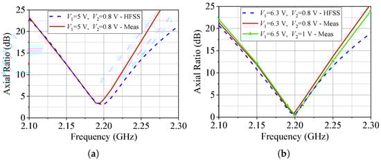
Figure 11.
Broadside AR. (a) Configuration 2. (b) Configuration 3.
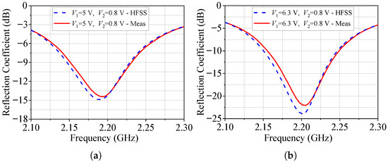
Figure 12.
Reflection coefficient. (a) Configuration 2. (b) Configuration 3.
As observed in the above study, the AR level and the reflection coefficient calculated in HFSS are well matched to the experimental results. This suggests that the model proposed for the antenna, including its varicap diodes, is a powerful tool for predicting the antenna performance and accurately determining the voltages and that lead to the desired performance.
3. Antenna Array
A six-element linear array using the reconfigurable antenna of Section 2 was designed to demonstrate the concept of tuning the polarization sense and AR of the main beam of a phased array for the various pointing directions.
3.1. Array Design
The model of the designed array is shown in Figure 13. It is composed of six radiators whose geometry is defined in Section 2.2. The ground plane and dielectric substrate (, , and mm) have a length of 481.85 mm and a width of 100 mm. The distance between the centers of adjacent patches is 76.37 mm (i.e., at 2.2 GHz), which establishes an operation similar to that of the array presented in [61]. Due to the tuning capability brought by the diodes, no optimizations were performed in the patches’ dimensions; therefore, the effects of mutual coupling and ground plane dimensions on the AR are compensated by adjusting the varicap bias voltages. The only parameter optimized at this stage is the probe position , in order to achieve good impedance matching for a set of steering angles, as we will be shown later in this section. We emphasize that the optimization of focuses on impedance matching since polarization sense and axial ratio control are achieved through the tuning of the varicaps.
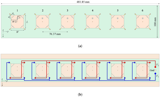
Figure 13.
Array of reconfigurable antennas. (a) Top view. (b) Bottom view.
The bottom view of the array, illustrated in Figure 13b, depicts the circuit for the diodes’ bias voltages, where blue lines provide DC voltages for the D1 diode pairs, and the red lines provide DC voltages for the D2 diode pairs.
Once the array geometry is specified, the capability to tune the AR of the main beam for a range of pointing directions must be validated. At this stage, the array is analyzed in HFSS assuming mm (as computed in Section 2.2) and reverse voltages V and V (conditions for a single element to operate as an LHCP radiator at broadside, as indicated in Table 2). In this study, the elements are excited with the same amplitude and a progressive phase shift of , resulting in a beam-pointing angle in the -plane. As expected from [61], the AR of the main beam is 4.9 dB, indicating poor circular polarization performance at the main beam maximum direction.
Next, a level curve for the AR in the direction on the -plane and 2.2 GHz as a function of and , similar to that of Figure 10a, was derived from HFSS results and is represented in Figure 14. The diodes are also modeled in the array elements through RLC series circuits with resistance and capacitance given by (3) and (4), respectively, and inductance of 0.6 nH. From Figure 14, we can see that the AR is lower than 3 dB for the voltages in the region bounded by the green line. The minimum value of AR (which is equal to 0.8 dB) is obtained for V and V, confirming that the AR at the main beam maximum can be tuned by controlling and in the array, thereby compensating for effects such as mutual coupling, which are responsible for degrading the array’s axial ratio performance.
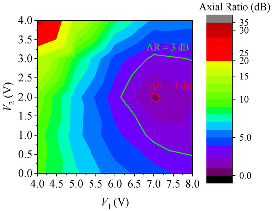
Figure 14.
AR of the main beam as a function of and at 2.2 GHz.
To find the best probe position, , we carried out a parametric analysis in HFSS starting from 9.20 mm. For each position , the array elements were fed with seven different sets of excitations (incident voltage waves), enabling the main beam to steer from to , as outlined in Table 4. We adopted the Dolph-Chebyshev amplitude distribution with a sidelobe level, SLL, of dB and a uniform progressive phase to generate these excitations [68]. The varicap bias voltages were adjusted to minimize the AR at the main beam maximum direction at 2.2 GHz for each set of excitations (i.e., for the seven proposed patterns). Subsequently, the active input impedances were computed at 2.2 GHz for each set of excitations and tuned bias voltages. This analysis revealed that for mm, the active input impedances fall within the circle of radius dB on the Smith chart, as illustrated in Figure 15. This demonstrates that the array elements can be well-matched for the seven main beam pointing directions considered.
Table 4.
Excitation coefficients of the array.
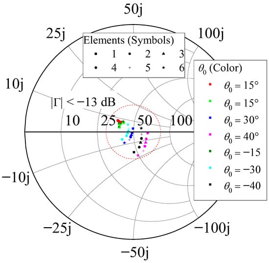
Figure 15.
Reflection coefficient at 2.2 GHz for = 9.50 mm.
The DC bias voltages and tuned for mm are listed in Table 5, along with the respective axial ratios at the main beam maximum direction at 2.2 GHz. It is noteworthy that axial ratios close to 0 dB are achieved for both RHCP and LHCP states, proving evidence of the array’s capability to generate circular polarization as its main beam is electronically steered. Figure 16 illustrates the array co-polar and cross-polar patterns in the -plane at 2.2 GHz for and , considering the RHCP and LHCP states. As can be observed from this figure, the axial ratio remains low in the vicinity of the main beam maximum since a low cross-polarization level is verified over the half-power beamwidth.
Table 5.
DC bias voltages and AR at the main beam at 2.2 GHz.
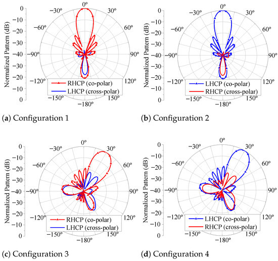
Figure 16.
Radiation pattern of the reconfigurable array in the -plane at 2.2 GHz. (a) with the RHCP state. (b) with the LHCP state. (c) with the RHCP state. (d) with the LHCP state.
In conclusion, the radiation efficiency of the designed array was analyzed and computed. Considering that the selected diode has a non-negligible series resistance, which can impact the array efficiency, an HFSS analysis was performed, indicating a radiation efficiency of 73%, a value that is acceptable for electrically thin microstrip radiators [65].
3.2. Array Prototype
To validate the proposed reconfigurable array and its design procedure, we built a prototype using Rogers CuClad 250 laminate with a thickness of 3.048 mm. The prototype top view is presented in Figure 17a, while the bottom view, containing the circuit for DC bias, is depicted in Figure 17b. The bias lines were printed on an FR-4 laminate with a thickness of 0.3 mm, positioned just beneath the array ground plane.
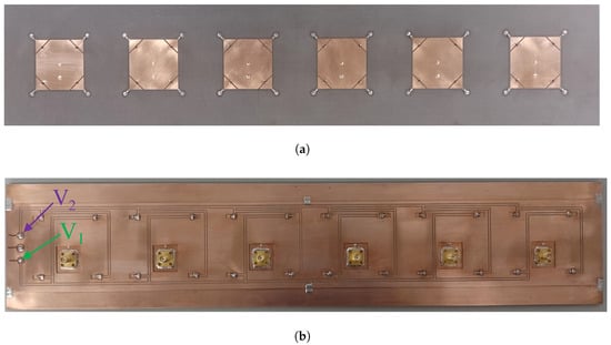
Figure 17.
Array prototype. (a) Top view. (b) Bottom view.
The array prototype was integrated with a closed-loop controlled microwave beamformer [64], as shown in Figure 18, creating a reconfigurable circularly polarized phased array. This beamformer enables the electronic control of both the amplitude and phase of the array excitations, allowing for changes in the synthesized pattern. In the anechoic chamber setup of Figure 18, two Agilent U8001-A DC power supplies were used to provide the diode bias voltages, and a horn antenna with linear polarization was operated as a transmitter.
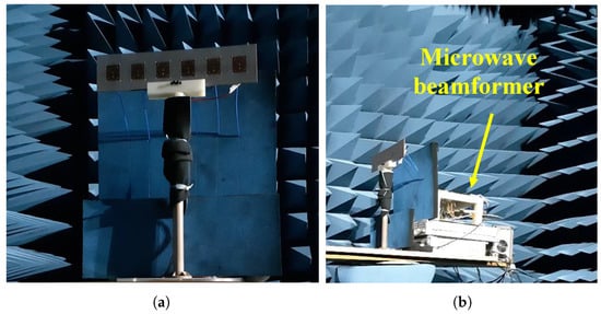
Figure 18.
Reconfigurable phased array in the anechoic chamber. (a) Antenna array. (b) Microwave beamformer.
Three steering angles, , were considered in the prototype tests, namely (broadside), , and , as well as both RHCP and LHCP states. We limited the main beam to because, beyond this value, a grating lobe appears in the pattern, although the polarization sense and axial ratio can still be controlled to some extent. The setup configuration for fine-tuning the bias voltages follows the steps described below.
Initially, for each steering angle, the excitation coefficients listed in Table 4 are set in the microwave beamformer, and the DC bias voltages of the varicaps are adjusted according to the values in Table 5. Next, the and radiation patterns in the -plane and 2.2 GHz are measured, allowing the determination of the normalized patterns (proportional to ). In all cases considered in this work, the measured angle of maximum radiation was consistent with the theoretical prediction.
Afterward, the main beam of the array pattern is aligned with that of the transmitting horn antenna. By rotating the horn antenna about its symmetry axis, we measure the axial ratio at 2.2 GHz, and we can minimize it by fine-tuning the bias voltages. These voltages are adjusted until an axial ratio below 1 dB is obtained since it leads to a 3 dB AR bandwidth equivalent to that computed in the array simulation. At the end of this stage, an updated set of DC voltages is then found, as reported in Table 6. Note that the adjusted voltages are very close to the corresponding theoretical predictions of Table 5, with a maximum deviation of only 0.4 V, showing that the proposed model provides good estimates to configure the phased array parameters. Furthermore, this analysis indicates that the capacitance temperature dependence can be compensated for via this technique, even though the variation of 0.03 %/°C for the selected diode BB833 is very small for this application.
Table 6.
Fine-tuned DC bias voltages of the phased array.
The measured patterns at 2.2 GHz for the three cases under consideration in this section are presented in Figure 19, Figure 20 and Figure 21. The simulated patterns computed in HFSS are shown in these figures for comparison purposes. Additionally, we measured the axial ratio at the main beam maximum direction in the range of 2.18 to 2.22 GHz, as seen in these last three figures. Notice that the axial ratio remains below 3.0 dB over a bandwidth slightly greater than 20 MHz for the three main beam pointing angles and LHCP and RHCP states. Also, there is good agreement between the measured and simulated results, thus validating the use of varicap diodes to control the axial ratio and polarization sense in a circularly polarized phased array.
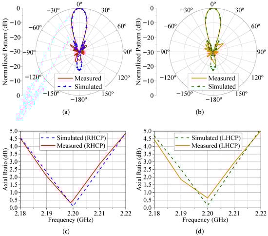
Figure 19.
Radiation patterns and AR for . (a) Radiation pattern (total field) for the RHCP configuration. (b) Radiation pattern (total field) for the LHCP configuration. (c) RHCP broadside axial ratio. (d) LHCP broadside axial ratio.

Figure 20.
Radiation patterns and AR for . (a) Radiation pattern (total field) for the RHCP configuration. (b) Radiation pattern (total field) for the LHCP configuration. (c) RHCP broadside axial ratio. (d) LHCP broadside axial ratio.
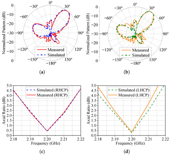
Figure 21.
Radiation patterns and AR for . (a) Radiation pattern (total field) for the RHCP configuration. (b) Radiation pattern (total field) for the LHCP configuration. (c) RHCP broadside axial ratio. (d) LHCP broadside axial ratio.
Two additional pattern configurations are synthesized to demonstrate the potential of the proposed system. In the first one, the microwave beamformer is set to feed the array elements with incident voltage waves of equal amplitude and uniform progressive phase that steer the main beam to . Table 7 provides the excitation coefficients for this configuration. One of the purposes of this analysis is to show that the varicaps bias voltages are weakly dependent on the amplitude of the excitations if the resulting patterns exhibit a certain degree of resemblance. To accomplish this, the DC voltages presented in Table 5 for , determined in HFSS assuming a Dolph–Chebyshev amplitude distribution and a uniform progressive phase, are applied to the varicaps.
Table 7.
Excitation coefficients of the array for the two additional configurations.
Following the procedure described before to configure the setup, we obtain the experimentally tuned DC voltages reported in Table 8, ensuring an AR at the main beam maximum at 2.2 GHz. Note that the maximum deviation between these voltages and the corresponding ones in Table 5 is only 0.5 V, showing that is not critical to start the tuning process from the theoretical bias voltages computed in HFSS for a related radiation pattern. Figure 22 illustrates the simulated and measured patterns in the -plane at 2.2 GHz for this first configuration, as well as the AR frequency response at the main beam maximum. Once again, the experimental results agree very well with the theoretical predictions.
Table 8.
DC bias voltages after fine-tuning for the two additional configurations.
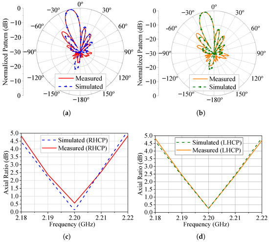
Figure 22.
Radiation patterns and AR for . (a) Radiation pattern (total field) for the RHCP configuration. (b) Radiation pattern (total field) for the LHCP configuration. (c) RHCP broadside axial ratio. (d) LHCP broadside axial ratio.
The second configuration consists of a multibeam pattern with two main lobes, one steered to and the other to , with SLL dB. The nonlinear constrained beamforming algorithm described in [69] was employed to calculate the excitation coefficients that synthesize such a pattern, and these coefficients are summarized in Table 7. Due to the symmetry of the array and the proposed pattern, the two beams are expected to have the same polarization states. Minor differences between their axial ratios may arise from fabrication tolerances and small asymmetries in the beamforming excitations.
According to [70], running the beamforming algorithm requires knowledge of the active-element patterns of the six reconfigurable antennas in the array. However, since the DC bias voltages are only defined in our procedure after evaluating the excitation coefficients, these active patterns are not known beforehand. To overcome this issue, we extract the active patterns from HFSS considering the DC bias voltages found in Table 5 for the broadside operation (i.e., ). This strategy has proven to be effective because, as will be shown below, the measured pattern preserves the two beams at after tuning the bias voltages in the prototype.
Since there are now two main lobes, we choose that at to adjust the bias voltages and thus minimize the axial ratio. Due to the array symmetry, it is expected to obtain the same polarization sense and a low AR at the other direction of maximum radiation, i.e., . Table 8 lists the DC bias voltages tuned experimentally for both RHCP and LHCP states. The comparisons between the measured and simulated patterns in the -plane and at 2.2 GHz are shown in Figure 23. Good agreement is noted between the two. Figure 23 also presents the AR frequency response in the directions of maximum radiation. Once again, a good agreement is indicated, with only a small frequency shift of 3 MHz for the measured LHCP AR at . In addition, the ARs measured at 2.2 GHz are less than or equal to approximately 1 dB.
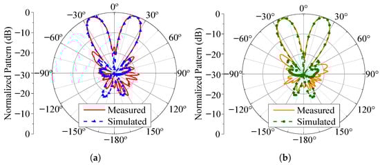
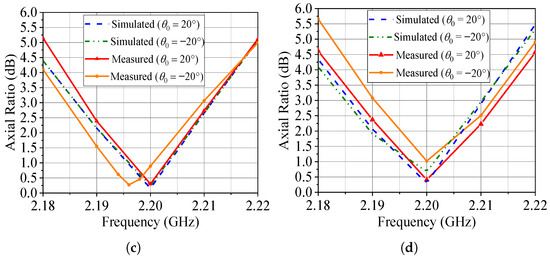
Figure 23.
Radiation patterns and AR for . (a) Radiation pattern (total field) for RHCP configuration. (b) Radiation pattern (total field) for LHCP configuration. (c) RHCP broadside axial ratio. (d) LHCP broadside axial ratio.
4. Conclusions
In this manuscript, we have presented the design of a novel circularly polarized phased array whose axial ratio and polarization sense at the main beam direction can be electronically reconfigured. To achieve such control, the array elements consist of single-fed microstrip antennas with a rectangular patch that has four truncated corners, each loaded with a varicap diode. The accurate adjustment of the DC bias voltages applied to the varicaps enables steering the direction of minimum AR. To the best of the authors’ knowledge, it is the first time that this radiator has been used in a phased array for polarization control.
The detailed design of the reconfigurable microstrip antenna is comprehensively discussed in the paper. The approach involves deriving an equivalent RLC series circuit to model the varicap diodes of the antenna. Simple and accurate expressions for the capacitance and resistance as functions of the reverse bias voltage are determined with the aid of HFSS optimization tools, making use of the measured input impedance of the antenna prototype. The tests of the prototype in the anechoic chamber confirm that the bias voltages derived from the model lead to measured axial ratios and reflection coefficients very close to the theoretical predictions.
This work has also shown that fine-tuning the bias voltages of the phased array can produce axial ratios as low as 1 dB in the main beam direction for both RHCP and LHCP states over a wide range of main beam pointing angles, as experimentally demonstrated in Figure 19, Figure 20, Figure 21 and Figure 22. It is an interesting feature that can serve as a means to compensate for minor disturbances, such as small objects near the array, the variability in the varicaps, or temperature variations, which might not have been initially considered in the phased array design. Examples of measured patterns and AR responses for nonuniform and uniform excitations are presented, and we observe a good agreement with the simulation results. Additionally, the paper introduces a procedure for synthesizing a dual-beam pattern with circular polarization using the designed phased array, as demonstrated in Figure 23.
Future work will explore the use of the proposed phased array to generate other polarization states, such as linear polarization. As illustrated in Figure 10a, certain combinations of bias voltages (e.g., ) lead to an axial ratio at broadside exceeding 40 dB, indicating the microstrip antenna’s linear polarization. Subsequent analyses are necessary to identify the voltages that guarantee proper impedance matching in this new state.
Author Contributions
Conceptualization, E.S.S., B.M.F., F.F.O., J.M.V., D.B.F. and D.C.N.; methodology, E.S.S., B.M.F., F.F.O., J.M.V., D.B.F. and D.C.N.; software, B.M.F., F.F.O. and D.C.N.; validation, E.S.S., F.F.O., J.M.V., D.B.F. and D.C.N.; formal analysis, E.S.S., B.M.F., F.F.O., J.M.V., D.B.F. and D.C.N.; investigation, E.S.S., B.M.F., F.F.O., J.M.V., D.B.F. and D.C.N.; writing—original draft preparation, J.M.V., D.B.F. and D.C.N.; writing—review and editing, J.M.V., D.B.F. and D.C.N.; visualization, D.B.F. and D.C.N.; supervision, D.B.F. and D.C.N.; project administration, D.C.N.; funding acquisition, D.C.N. All authors have read and agreed to the published version of the manuscript.
Funding
This research was funded by the National Council for Scientific and Technological Development—CNPq—Brazil, under grant numbers 166603/2017-1, 157888/2019-3, 405889/2021-6, and 305944/2023-1.
Institutional Review Board Statement
Not applicable.
Informed Consent Statement
Not applicable.
Data Availability Statement
Data is contained within the article.
Acknowledgments
The authors would like to express their gratitude to the Institute for Promotion and Industrial Coordination—IFI/DCTA—for making its anechoic chamber available.
Conflicts of Interest
The authors declare no conflicts of interest. The funders played no role in the design of the study, in the collection, analysis, or interpretation of data, in the writing of the manuscript, or in the decision to publish the results.
References
- Haupt, R.L.; Rahmat-Samii, Y. Antenna Array Developments: A Perspective on the Past, Present and Future. IEEE Antennas Propag. Mag. 2015, 57, 86–96. [Google Scholar] [CrossRef]
- Soumekh, M. Phased array imaging of moving targets with randomized beam steering and area spotlighting. IEEE Trans. Image Process. 1997, 6, 736–749. [Google Scholar] [CrossRef] [PubMed]
- Prather, D.W.; Murakowski, J.A.; Schuetz, C.; Shi, S.; Schneider, G.J.; Harrity, C.; Aranda, Z.D.; Marinucci, D.; Hallak, A.; Zablocki, M.; et al. Millimeter-Wave and Sub-THz Phased-Array Imaging Systems Based on Electro-Optic Up-Conversion and Optical Beamforming. IEEE J. Sel. Top. Quantum Electron. 2023, 29, 8501014. [Google Scholar] [CrossRef]
- Chen, C.N.; Lin, Y.H.; Hung, L.C.; Tang, T.C.; Chao, W.P.; Chen, C.Y.; Chuang, P.H.; Lin, G.Y.; Liao, W.J.; Nien, Y.H.; et al. 38-GHz Phased Array Transmitter and Receiver Based on Scalable Phased Array Modules with Endfire Antenna Arrays for 5G MMW Data Links. IEEE Trans. Microw. Theory Tech. 2021, 69, 980–999. [Google Scholar] [CrossRef]
- Zhao, K.; Ying, Z.; He, S. EMF Exposure Study Concerning mmWave Phased Array in Mobile Devices for 5G Communication. IEEE Antennas Wirel. Propag. Lett. 2016, 15, 1132–1135. [Google Scholar] [CrossRef]
- Kowalski, M.; Behnia, B.; Webb, A.; Jin, J.M. Optimization of electromagnetic phased-arrays for hyperthermia via magnetic resonance temperature estimation. IEEE Trans. Biomed. Eng. 2002, 49, 1229–1241. [Google Scholar] [CrossRef]
- Baskaran, D.; Arunachalam, K. Implementation of Thinned Array Synthesis in Hyperthermia Treatment Planning of 434 MHz Phased Array Breast Applicator Using Genetic Algorithm. IEEE J. Electromagn. Rf Microwaves Med. Biol. 2023, 7, 32–38. [Google Scholar] [CrossRef]
- Palmer, R.D.; Yeary, M.B.; Schvartzman, D.; Salazar-Cerreno, J.L.; Fulton, C.; McCord, M.; Cheong, B.; Bodine, D.; Kirstetter, P.; Sigmarsson, H.H.; et al. Horus—A Fully Digital Polarimetric Phased Array Radar for Next-Generation Weather Observations. IEEE Trans. Radar Syst. 2023, 1, 96–117. [Google Scholar] [CrossRef]
- Pan, S.; Ye, X.; Zhang, Y.; Zhang, F. Microwave Photonic Array Radars. IEEE J. Microwaves 2021, 1, 176–190. [Google Scholar] [CrossRef]
- Ma, Y.; Long, W.; Miao, C.; Chen, Q.; Zhang, J.; Yu, Y.; Wu, W. Enhanced dual lane detection in automotive radar systems using harmonic coordinated beamforming of time-modulated arrays. Wirel. Netw. 2025, 31, 1801–1812. [Google Scholar] [CrossRef]
- Hansen, R.C. Phased Array Antennas, 2nd ed.; Wiley: Hoboken, NJ, USA, 2009. [Google Scholar]
- Mailloux, R.J. Phased Array Antenna Handbook, 3rd ed.; Artech House: Norwood, MA, USA, 2018. [Google Scholar]
- Topak, E.; Hasch, J.; Wagner, C.; Zwick, T. A Novel Millimeter-Wave Dual-Fed Phased Array for Beam Steering. IEEE Trans. Microw. Theory Tech. 2013, 61, 3140–3147. [Google Scholar] [CrossRef]
- Chatterjee, S.; Chatterjee, S.; Majumdar, A. Edge Element Controlled Null Steering in Beam-Steered Planar Array. IEEE Antennas Wirel. Propag. Lett. 2017, 16, 2521–2524. [Google Scholar] [CrossRef]
- Rocca, P.; Poli, L.; Polo, A.; Massa, A. Optimal Excitation Matching Strategy for Sub-Arrayed Phased Linear Arrays Generating Arbitrary-Shaped Beams. IEEE Trans. Antennas Propag. 2020, 68, 4638–4647. [Google Scholar] [CrossRef]
- Li, M.; Liu, Y.; Guo, Y.J. Shaped Power Pattern Synthesis of a Linear Dipole Array by Element Rotation and Phase Optimization Using Dynamic Differential Evolution. IEEE Antennas Wirel. Propag. Lett. 2018, 17, 697–701. [Google Scholar] [CrossRef]
- Chen, Z.; Song, Z.; Liu, H.; Yu, J.; Chen, X. Passive-Shaped Beam Synthesis Using Pattern Diversity Dielectric Resonator Antenna Array. IEEE Antennas Wirel. Propag. Lett. 2021, 20, 1115–1119. [Google Scholar] [CrossRef]
- He, G.; Gao, X.; Sun, L.; Zhang, R. A Review of Multibeam Phased Array Antennas as LEO Satellite Constellation Ground Station. IEEE Access 2021, 9, 147142–147154. [Google Scholar] [CrossRef]
- Haupt, R.L.; Lanagan, M. Reconfigurable Antennas. IEEE Antennas Propag. Mag. 2013, 55, 49–61. [Google Scholar] [CrossRef]
- Ali, M. Reconfigurable Antenna Design and Analysis, 1st ed.; Artech House: Norwood, MA, USA, 2021. [Google Scholar]
- Christodoulou, C.G.; Tawk, Y.; Lane, S.A.; Erwin, S.R. Reconfigurable Antennas for Wireless and Space Applications. Proc. IEEE 2012, 100, 2250–2261. [Google Scholar] [CrossRef]
- Lin, Z.; Niu, H.; He, Y.; An, K.; Zhong, X.; Chu, Z. Self-powered absorptive reconfigurable intelligent surfaces for securing satellite-terrestrial integrated networks. China Commun. 2024, 21, 276–291. [Google Scholar] [CrossRef]
- dos Santos Silveira, E.; Antreich, F.; do Nascimento, D.C. Frequency-reconfigurable SIW microstrip antenna. AEU Int. J. Electron. Commun. 2020, 124, 153333. [Google Scholar] [CrossRef]
- Borhani, M.; Rezaei, P.; Valizade, A. Design of a Reconfigurable Miniaturized Microstrip Antenna for Switchable Multiband Systems. IEEE Antennas Wirel. Propag. Lett. 2016, 15, 822–825. [Google Scholar] [CrossRef]
- Mansoul, A.; Ghanem, F.; Hamid, M.R.; Trabelsi, M. A Selective Frequency-Reconfigurable Antenna for Cognitive Radio Applications. IEEE Antennas Wirel. Propag. Lett. 2014, 13, 515–518. [Google Scholar] [CrossRef]
- Sun, C.; Zheng, H.; Zhang, L.; Liu, Y. A Compact Frequency-Reconfigurable Patch Antenna for Beidou (COMPASS) Navigation System. IEEE Antennas Wirel. Propag. Lett. 2014, 13, 967–970. [Google Scholar] [CrossRef]
- Jin, G.; Li, M.; Liu, D.; Zeng, G. A Simple Planar Pattern-Reconfigurable Antenna Based on Arc Dipoles. IEEE Antennas Wirel. Propag. Lett. 2018, 17, 1664–1668. [Google Scholar] [CrossRef]
- Pablo Zapata Cano, H.; Zaharis, Z.D.; Yioultsis, T.V.; Kantartzis, N.V.; Lazaridis, P.I. Pattern Reconfigurable Antennas at Millimeter-Wave Frequencies: A Comprehensive Survey. IEEE Access 2022, 10, 83029–83042. [Google Scholar] [CrossRef]
- Bai, Y.Y.; Xiao, S.; Tang, M.C.; Ding, Z.F.; Wang, B.Z. Wide-Angle Scanning Phased Array with Pattern Reconfigurable Elements. IEEE Trans. Antennas Propag. 2011, 59, 4071–4076. [Google Scholar] [CrossRef]
- Cheng, Y.F.; Ding, X.; Shao, W.; Wang, B.Z. Planar Wide-Angle Scanning Phased Array with Pattern-Reconfigurable Windmill-Shaped Loop Elements. IEEE Trans. Antennas Propag. 2017, 65, 932–936. [Google Scholar] [CrossRef]
- Zhang, J.; Zhang, S.; Ying, Z.; Morris, A.S.; Pedersen, G.F. Radiation-Pattern Reconfigurable Phased Array with p-i-n Diodes Controlled for 5G Mobile Terminals. IEEE Trans. Microw. Theory Tech. 2020, 68, 1103–1117. [Google Scholar] [CrossRef]
- Rhee, C.; Kim, Y.; Park, T.; Kwoun, S.s.; Mun, B.; Lee, B.; Jung, C. Pattern-Reconfigurable MIMO Antenna for High Isolation and Low Correlation. IEEE Antennas Wirel. Propag. Lett. 2014, 13, 1373–1376. [Google Scholar] [CrossRef]
- Sun, H.; Hu, Y.; Ren, R.; Zhao, L.; Li, F. Design of Pattern-Reconfigurable Wearable Antennas for Body-Centric Communications. IEEE Antennas Wirel. Propag. Lett. 2020, 19, 1385–1389. [Google Scholar] [CrossRef]
- Qin, P.Y.; Weily, A.R.; Guo, Y.J.; Liang, C.H. Polarization Reconfigurable U-Slot Patch Antenna. IEEE Trans. Antennas Propag. 2010, 58, 3383–3388. [Google Scholar] [CrossRef]
- Chen, S.L.; Wei, F.; Qin, P.Y.; Guo, Y.J.; Chen, X. A Multi-linear Polarization Reconfigurable Unidirectional Patch Antenna. IEEE Trans. Antennas Propag. 2017, 65, 4299–4304. [Google Scholar] [CrossRef]
- Chen, Q.; Li, J.Y.; Yang, G.; Cao, B.; Zhang, Z. A Polarization-Reconfigurable High-Gain Microstrip Antenna. IEEE Trans. Antennas Propag. 2019, 67, 3461–3466. [Google Scholar] [CrossRef]
- Bhattacharjee, A.; Dwari, S.; Mandal, M.K. Polarization-Reconfigurable Compact Monopole Antenna with Wide Effective Bandwidth. IEEE Antennas Wirel. Propag. Lett. 2019, 18, 1041–1045. [Google Scholar] [CrossRef]
- Huang, C.; Pan, W.; Ma, X.; Zhao, B.; Cui, J.; Luo, X. Using Reconfigurable Transmitarray to Achieve Beam-Steering and Polarization Manipulation Applications. IEEE Trans. Antennas Propag. 2015, 63, 4801–4810. [Google Scholar] [CrossRef]
- Di Palma, L.; Clemente, A.; Dussopt, L.; Sauleau, R.; Potier, P.; Pouliguen, P. Circularly-Polarized Reconfigurable Transmitarray in Ka-Band with Beam Scanning and Polarization Switching Capabilities. IEEE Trans. Antennas Propag. 2017, 65, 529–540. [Google Scholar] [CrossRef]
- Ge, L.; Yang, X.; Zhang, D.; Li, M.; Wong, H. Polarization-Reconfigurable Magnetoelectric Dipole Antenna for 5G Wi-Fi. IEEE Antennas Wirel. Propag. Lett. 2017, 16, 1504–1507. [Google Scholar] [CrossRef]
- Guo, T.; Leng, W.; Wang, A.; Li, J.; Zhang, Q. A Novel Planar Parasitic Array Antenna with Frequency- and Pattern-Reconfigurable Characteristics. IEEE Antennas Wirel. Propag. Lett. 2014, 13, 1569–1572. [Google Scholar] [CrossRef]
- Nikolaou, S.; Bairavasubramanian, R.; Lugo, C.; Carrasquillo, I.; Thompson, D.; Ponchak, G.; Papapolymerou, J.; Tentzeris, M. Pattern and frequency reconfigurable annular slot antenna using PIN diodes. IEEE Trans. Antennas Propag. 2006, 54, 439–448. [Google Scholar] [CrossRef]
- Qin, P.Y.; Guo, Y.J.; Cai, Y.; Dutkiewicz, E.; Liang, C.H. A Reconfigurable Antenna with Frequency and Polarization Agility. IEEE Antennas Wirel. Propag. Lett. 2011, 10, 1373–1376. [Google Scholar] [CrossRef]
- Zhang, T.; Chen, Y.; Yang, S. A Wideband Frequency- and Polarization-Reconfigurable Liquid Metal-Based Spiral Antenna. IEEE Antennas Wirel. Propag. Lett. 2022, 21, 1477–1481. [Google Scholar] [CrossRef]
- Bhattacharjee, A.; Dwari, S. A Monopole Antenna with Reconfigurable Circular Polarization and Pattern Tilting Ability in Two Switchable Wide Frequency Bands. IEEE Antennas Wirel. Propag. Lett. 2021, 20, 1661–1665. [Google Scholar] [CrossRef]
- Hu, J.; Yang, X.; Ge, L.; Guo, Z.; Hao, Z.C.; Wong, H. A Reconfigurable 1 × 4 Circularly Polarized Patch Array Antenna with Frequency, Radiation Pattern, and Polarization Agility. IEEE Trans. Antennas Propag. 2021, 69, 5124–5129. [Google Scholar] [CrossRef]
- Zhang, Y.; Lin, S.; Li, Y.; Cui, J.; Dai, F.; Jiao, J.; Denisov, A. Wideband Pattern- and Polarization-Reconfigurable Antenna Based on Bistable Composite Cylindrical Shells. IEEE Access 2020, 8, 66777–66787. [Google Scholar] [CrossRef]
- Liu, X.; Leung, K.W.; Zhang, T.; Yang, N.; Gu, P.; Chen, R. An Electrically Controlled Pattern- and Polarization-Reconfigurable Cylindrical Dielectric Resonator Antenna. IEEE Antennas Wirel. Propag. Lett. 2021, 20, 2309–2313. [Google Scholar] [CrossRef]
- Raman, S.; Mohanan, P.; Timmons, N.; Morrison, J. Microstrip-Fed Pattern- and Polarization- Reconfigurable Compact Truncated Monopole Antenna. IEEE Antennas Wirel. Propag. Lett. 2013, 12, 710–713. [Google Scholar] [CrossRef]
- McMichael, I.T. A Mechanically Reconfigurable Patch Antenna with Polarization Diversity. IEEE Antennas Wirel. Propag. Lett. 2018, 17, 1186–1189. [Google Scholar] [CrossRef]
- Jouade, A.; Himdi, M.; Chauloux, A.; Colombel, F. Mechanically Pattern-Reconfigurable Bended Horn Antenna for High-Power Applications. IEEE Antennas Wirel. Propag. Lett. 2017, 16, 457–460. [Google Scholar] [CrossRef]
- Grau, A.; Romeu, J.; Lee, M.J.; Blanch, S.; Jofre, L.; De Flaviis, F. A Dual-Linearly-Polarized MEMS-Reconfigurable Antenna for Narrowband MIMO Communication Systems. IEEE Trans. Antennas Propag. 2010, 58, 4–17. [Google Scholar] [CrossRef]
- Huff, G.; Bernhard, J. Integration of packaged RF MEMS switches with radiation pattern reconfigurable square spiral microstrip antennas. IEEE Trans. Antennas Propag. 2006, 54, 464–469. [Google Scholar] [CrossRef]
- Aboufoul, T.; Alomainy, A.; Parini, C. Reconfiguring UWB Monopole Antenna for Cognitive Radio Applications Using GaAs FET Switches. IEEE Antennas Wirel. Propag. Lett. 2012, 11, 392–394. [Google Scholar] [CrossRef]
- Quddious, A.; Abbasi, M.A.B.; Antoniades, M.A.; Vryonides, P.; Fusco, V.; Nikolaou, S. Dynamically Reconfigurable UWB Antenna Using an FET Switch Powered by Wireless RF Harvested Energy. IEEE Trans. Antennas Propag. 2020, 68, 5872–5881. [Google Scholar] [CrossRef]
- Dwivedy, B.; Behera, S.K. A Square-Shaped Microstrip Antenna with Frequency and Circular-Polarization Reconfigurability: An Approach [Antenna Applications Corner]. IEEE Antennas Propag. Mag. 2020, 62, 107–115. [Google Scholar] [CrossRef]
- Kang, L.; Li, H.; Wang, X.; Zhou, J.; Huang, J. Circular Polarization-Agile and Continuous Beam-Steerable Array Antenna Using a Hybrid Design Approach. IEEE Trans. Antennas Propag. 2022, 70, 1541–1546. [Google Scholar] [CrossRef]
- Banerjee, R.; Sharma, S.K.; Waldstein, S.W.; Downey, J.M.; Schoenholz, B.L.; Dever, S.M.; Nessel, J.A.; Das, S. A 22–28 GHz Polarization-Reconfigurable Flat-Panel 8 × 8 Tx/Rx Phased Array Antenna with Uniquely Arranged Novel Radiating Elements for CubeSat Communication. IEEE Trans. Antennas Propag. 2023, 71, 4138–4152. [Google Scholar] [CrossRef]
- Wei, Y.; Arnold, C.; Hong, J. Multiport Beamforming System Based on Reconfigurable Waveguide Phased Antenna Array for Satellite Communication Applications. IEEE Access 2023, 11, 29909–29917. [Google Scholar] [CrossRef]
- Hu, J.; Hao, Z.C. A Compact Polarization-Reconfigurable and 2-D Beam-Switchable Antenna Using the Spatial Phase Shift Technique. IEEE Trans. Antennas Propag. 2018, 66, 4986–4995. [Google Scholar] [CrossRef]
- dos Santos Silveira, E.; Fabiani, B.M.; de Pina, M.V.P.; Nascimento, D.C. Polarization reconfigurable microstrip phased array. AEU Int. J. Electron. Commun. 2018, 97, 220–228. [Google Scholar] [CrossRef]
- Silveira, E.S.; Nascimento, D.C.; da S. Lacava, J.C. Reconfigurable truncated corners microstrip antenna. In Proceedings of the 2015 SBMO/IEEE MTT-S International Microwave and Optoelectronics Conference (IMOC), Porto de Galinhas, Brazil, 3–6 November 2015; pp. 1–4. [Google Scholar] [CrossRef]
- Sung, Y.; Jang, T.; Kim, Y.S. A reconfigurable microstrip antenna for switchable polarization. IEEE Microw. Wirel. Components Lett. 2004, 14, 534–536. [Google Scholar] [CrossRef]
- Fabiani, B.M.; Oliveira, F.F.; Vieira, J.M.; Sakomura, E.S.; Silveira, E.S.; Nascimento, D.C.; Ferreira, D.B. Closed-loop controlled microwave beamformer. Int. J. Rf Microw. Comput. Aided Eng. 2022, 32, e23020. [Google Scholar] [CrossRef]
- Garg, R.; Bhartia, P.; Bahl, I.; Ittipiboon, A. Microstrip Antenna Design Handbook, 1st ed.; Artech House: Norwood, MA, USA, 2001. [Google Scholar]
- Walker, B. Make Accurate Impedance Measurements Using a VNA. Technical Report. 2019. Available online: https://www.mwrf.com/technologies/test-measurement/article/21849791/copper-mountain-technologies-make-accurate-impedance-measurements-using-a-vna (accessed on 14 March 2024).
- Nascimento, D.M.; Lacava, J.C.d.S. Design of low-cost probe-fed microstrip antenna. In Microstrip Antennas; Nasimuddin, N., Ed.; InTech: Rijeka, Croatia, 2011; pp. 1–26. [Google Scholar]
- Bahl, I. Lumped Elements for RF and Microwave Circuits, 1st ed.; Artech House: Norwood, MA, USA, 2003. [Google Scholar]
- Balanis, C.A. Antenna Theory: Analysis and Design, 4th ed.; Wiley: Hoboken, NJ, USA, 2016. [Google Scholar]
- Fabiani, B.M.; Silveira, E.S.; Pina, M.V.P.; Nascimento, D.C. Nonlinear Constrained Beamforming Algorithm for Circularly Polarized Phased Arrays. IEEE Antennas Wirel. Propag. Lett. 2018, 17, 1692–1696. [Google Scholar] [CrossRef]


Disclaimer/Publisher’s Note: The statements, opinions and data contained in all publications are solely those of the individual author(s) and contributor(s) and not of MDPI and/or the editor(s). MDPI and/or the editor(s) disclaim responsibility for any injury to people or property resulting from any ideas, methods, instructions or products referred to in the content. |
© 2025 by the authors. Licensee MDPI, Basel, Switzerland. This article is an open access article distributed under the terms and conditions of the Creative Commons Attribution (CC BY) license (https://creativecommons.org/licenses/by/4.0/).