1. Introduction
Due to their high-power density and other irreplaceable advantages, the surface-mounted permanent magnet (PM) machines (SMPMM) have been applied in many situations i.e., industrial manufacture, home automation, electro-mobile, robotics, etc. [
1,
2,
3,
4,
5,
6]. At present, people pay much attention to the weakening of the cogging torque, to the reduction in torque ripple, and to the suppression of the vibration or noise of the SMPMM [
7,
8,
9,
10,
11]. These are required in order to firstly obtain the magnetic flux density of the SMPMM. The magnetic flux density could be used to calculate the electromagnetic force, and that is the basis for analyzing the performance of the motor. At present, research on the prediction of magnetic field distribution is focused on SMPMMs with equal magnetic pole structures (SMPMM-EPMS), while the SMPMMs with unequal magnetic pole structures (SMPMM-UEPMS) are seldom mentioned [
12,
13,
14,
15]. But, because of errors, the ratio of the pole-arc to the pole-pitch, or the remanence of each PM, could not be exactly same, such that, in fact, SMPMM-UEPMS are widely used in engineering applications. However, the errors are so small that they can be ignored. This makes the model of SMPMM-UEPMS transform into the SMPMM-EPMS during the design and analysis process of the motor, which makes the issue simpler. Moreover, the electromagnetic characteristics of the motor can be changed by altering the configuration scheme of the PM. This is an effective way of improving the electromagnetic properties of the motor [
16]. Converting the configuration scheme of the PM includes mounting the PMs with different polar-arc coefficients or the PMs with different remanences. In general, several indexes are often considered, i.e., the torque, vibration, and noise characteristics, during the process of motor optimization design. Some studies indicated that the SMPMM-UEPMS has a smaller torque ripple than the SMPMM-EPMS, yet it brought more complexity to the characteristics of the noise or the vibration [
17]. Overall, the magnetic flux density of the SMPMM-UEPMS should be investigated.
Two basic methods have always been utilized to investigate magnetic field distribution or the other design parameters of the SMPMM, i.e., the finite element method (FEM) [
18,
19,
20] and the analytical calculation method [
21]. In reference [
22], by using the FEM, researchers investigated the rotor eccentricity situation and they obtained the influence of magnetic force by rotor eccentricity in the case of the PM direct current commutator machine. By employing the three-dimensional FEM, in reference [
23], the magnetic force was calculated and analyzed for the claw pole alternator. This study established a multi-physics simulation model to predict the vibration and noise of the motor. In reference [
24], a multi-phasic model was adopted to investigate the vibration problem caused by electromagnetic force. This study combined the 3D structural model, 2D FEM, and acoustic calculation model.
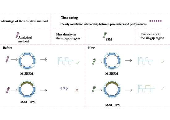
The FEM is an effective way to accurately obtain the magnetic field distribution. However, it always has the characteristics of a time-consuming and complicated pre-processing process. And the FEM does not give a clear correlation relationship between parameters and performances. Compared with the FEM, the analytical method takes less calculation time and the complex pre-processing process is not needed either. Furthermore, the analytical method offers an explicit relationship between the structural parameters and performances.
The analytical methods can be roughly divided into three directions, namely, the equivalent magnetic circuit (EMC) method [
25,
26], the sub-domain (SD) method [
27,
28], and the equivalent magnetization current (EMCT) method [
29,
30]. These analytical methods have their own advantages and scope of application. For example, the EMC can accurately calculate the magnetic field distribution under any pole-slot coordination. The SD method can directly obtain the magnetic field distribution of the motor with load. And the EMCT method can calculate the magnetic field distribution of the PM motor with different directions of PM magnetization. Analytical methods can also be used for the calculation of other aspects of the motor, such as the electromagnetic force, the vibration, the cogging torque, etc. Also, analytical methods can be used for different types of motors. In reference [
31], the researchers derived the air gap flux density distribution and the radial force density distribution. Then, based on their results, they studied the vibration characteristics of the PM motor. In reference [
32], a new magnetic equivalent circuit model was used to solve the complex saturation issue. It could accurately describe the magnetic potential distribution of the rotor surface. For the interior PM motor, the sub-domain method and the magnetic equivalent circuit method were separately adopted to obtain the flux density distribution of the motor [
33,
34]. For the axial-flux PM motors, the analytical method could also be adapted to obtain the open-circuit PMs field distribution and the torque ripple [
35,
36].
The magnetic flux density at the air gap can provide a reference for evaluating the motor performance. Although numerical analysis is the most common method for calculating magnetic flux density, it takes a long time to calculate even with a computer with strong performance. And it is difficult to embed an iterative process, so it is necessary to use an analytical method to accurately estimate the magnetic flux density at the air gap. However, the analytical methods or techniques mentioned before were focused on solving the issues of calculating the magnetic field distribution of the SMPMM-EPMS. Therefore, an analytical technique for calculating the flux density for the SMPMM-UEPMS should be proposed.
In this paper, an analytical technique to determine the magnet field distribution of the SMPMM-UEPMS is proposed. The technique is based on the Fourier series method and superposition method. To be specific, firstly, a two-dimensional analytical model abstracted from engineering practice is established. The schematic structure models and the topologies models for both the SMPMM-EPMS and SMPMM-UEPMS are established as well. Secondly, by solving the two types of equations governing the Laplacian field equations in the airgap region, and the Quasi-Poisson field equations in the magnetic region, the flux density produced by each PM pole is obtained. Thirdly, by summing the flux density results of each PM pole with different mounted angles, the whole magnetic flux density of the SMPMM-UEPMS is obtained. Finally, the calculation results of the technique proposed in this paper, called the Fourier series superposition method (SSM), are compared with the prediction results of the FEM. By comparing the calculation results, it could be found that the technique can be applied to calculate the magnetic field distribution generated by the PMs effectively and that the technique is effective for both the SMPMM-EPMS and SMPMM-UEPMS. Moreover, the armature reaction field and the slotting effect were taken into consideration as well.
2. Models and Methods
2.1. Analytical Magnetic Field Model
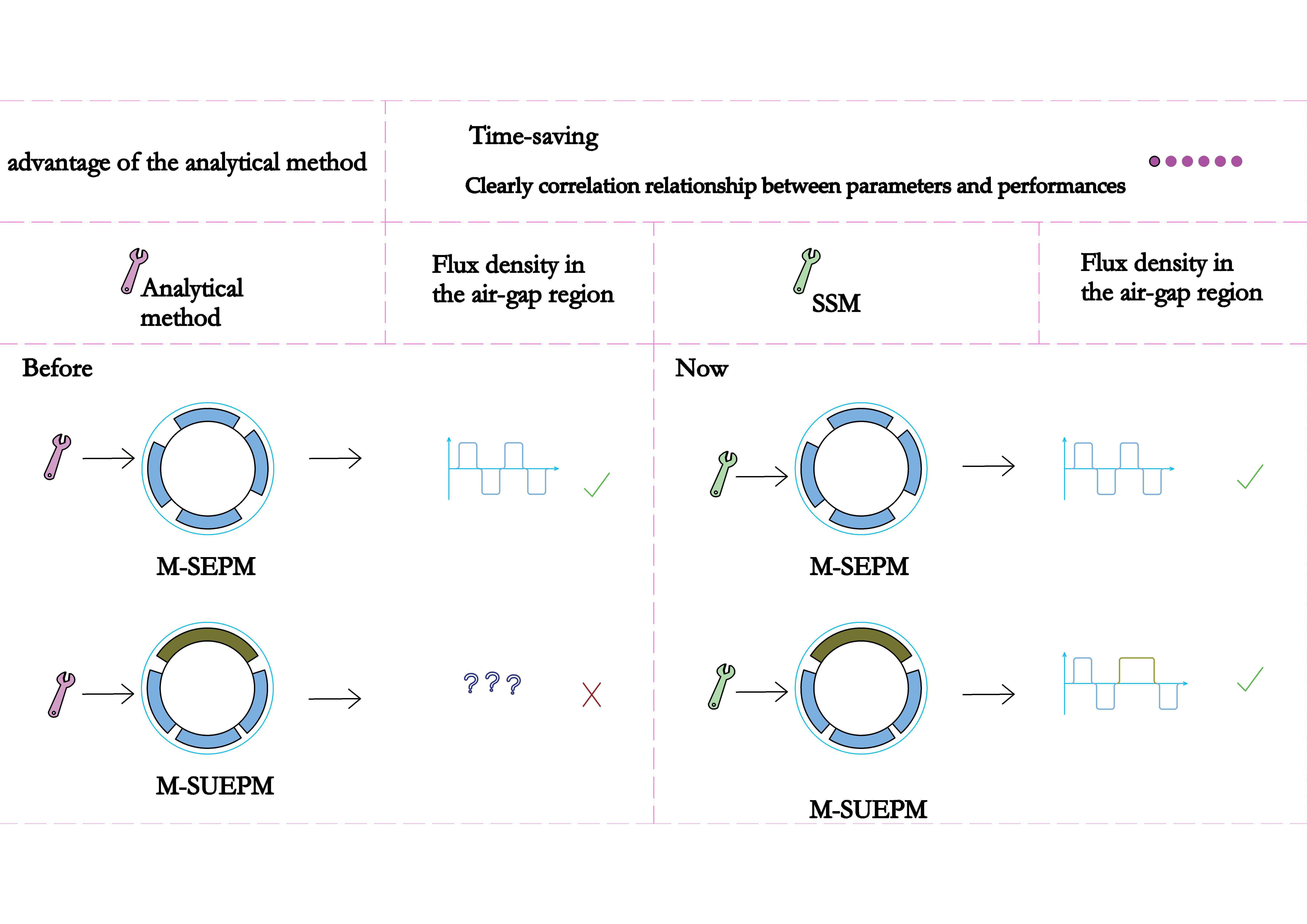
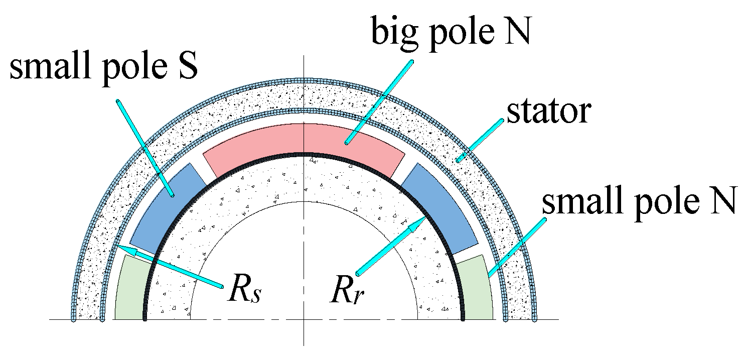
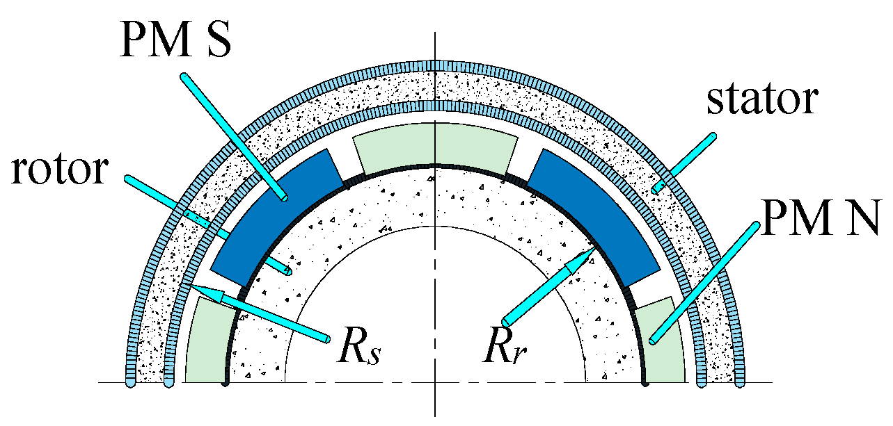
In this section, the 36-slots-8-poles motors of SMPMM-EPMS and SMPMM-UEPMS, which were both used in a practical project, are taken as examples to analyze and calculate the flux density using the SSM and FEM. The two-dimensional model of the SMPMM-UEPMS is shown in
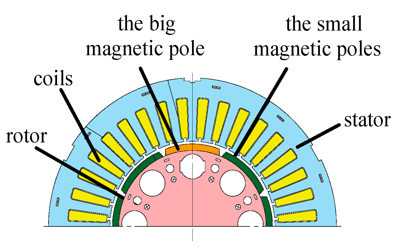
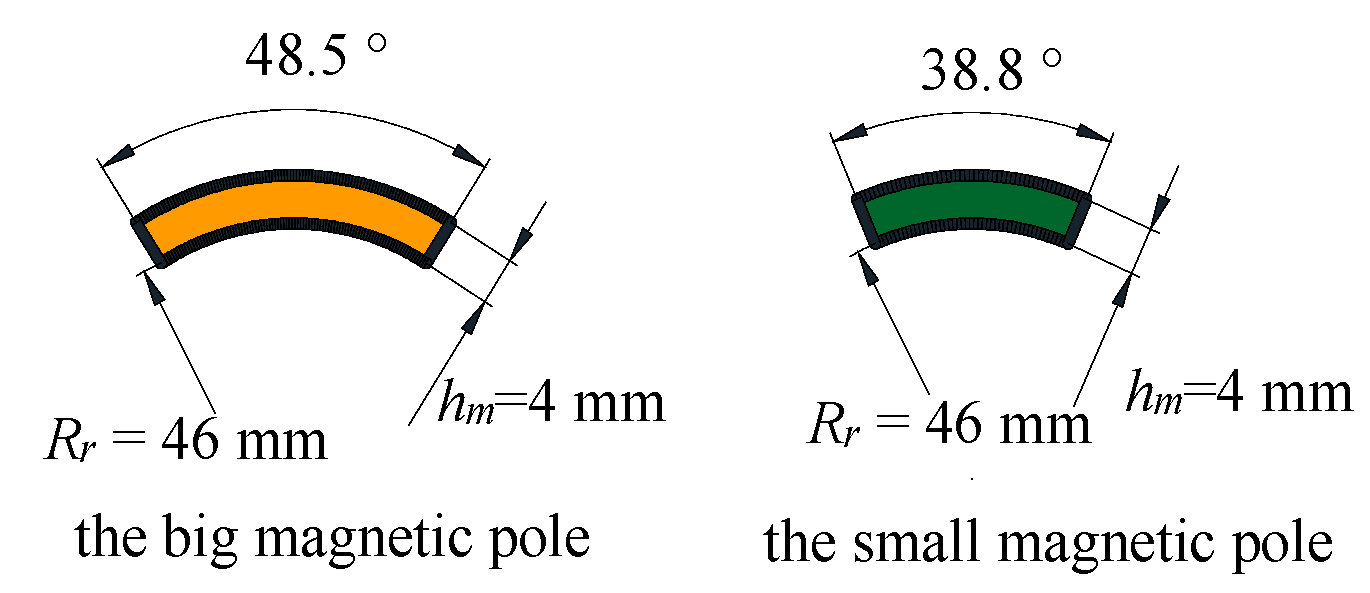
Figure 1. The structure and size of the big magnetic pole and small magnetic pole are shown in
Figure 2. Meanwhile, the schematic model for the SMPMM-UEPMS and the SMPMM-EPMS are, respectively, shown in
Figure 3 and
Figure 4.
In order to obtain the whole magnetic flux density generated by the PMs, we firstly obtained the field distribution generated by the big magnetic pole. Then, the field distribution of the other small magnetic poles could be obtained in the same way. Then, by applying the superposition rule, the whole field distribution of the SMPMM-UEPMS could be obtained. Similarly, for the SMPMM-EPMS, the magnetic field distribution of the motor could be obtained this way as well.
The model for the SMPMM-UEPMS contains one big permanent magnetic pole and seven small permanent magnetic poles in this section. Because the torque ripple and the vibration are relatively small, the SMPMM-UEPMS were designed for injection molding machines or the other machines which required a small torque ripple or vibration. The SSM could not only be applied to calculate the magnetic field distribution for this case, but it could also be applied to calculate the magnetic field distribution for the case of the model with different combinations or quantities of the big and the small magnetic poles. Similarly, the SSM is also applicable for the special case in which all the magnetic poles have the same ratio of pole-arc to pole-pitch (RPP). In that case, the model of SMPMM-UEPMS is transformed to the model of SMPMM-EPMS.
2.2. General Equations of the Flux Density
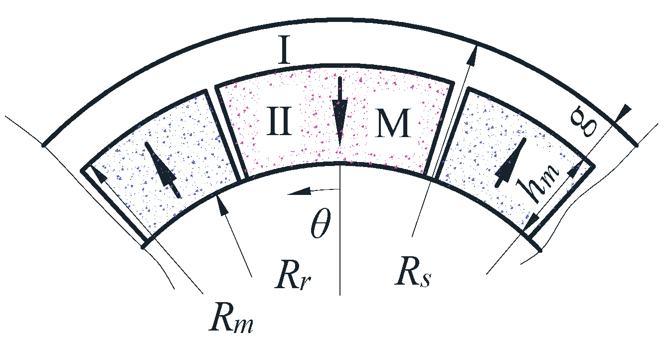
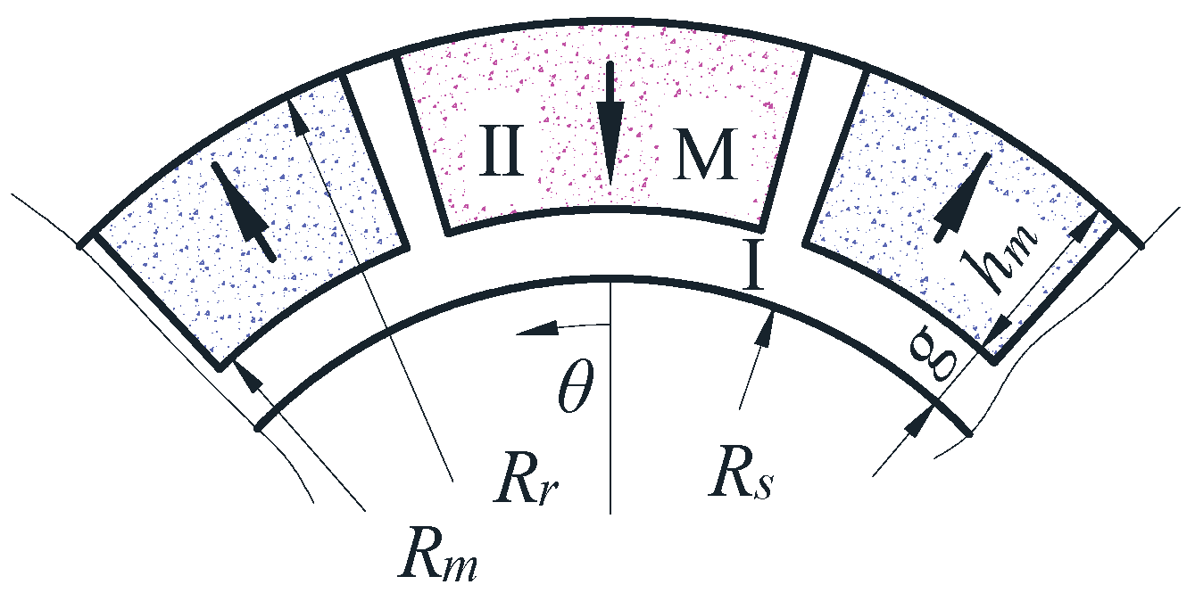
The topologies models of the external and internal rotor motors are shown in
Figure 5 and
Figure 6, and the magnetization distribution of one single PM is shown in
Figure 7. Simultaneously, some assumptions should be made as follows:
- (1)
The permeability of the iron and PMs are close to unity.
- (2)
The two-dimensional symmetry is valid, and the end effects are negligible.
- (3)
Only parallel-magnetized PMs are studied.
- (4)
Magnetic leakage is not considered.
- (5)
Magnetization is assumed to be uniform.
Rr represents the rotor radius,
Rs represents the stator’s inner surface radius, and
Rm represents the permanent magnet’s radius.
hm represents the thickness of the PM.
g represents the air gap length. The variable
θ represents the mounting center angle of the magnet pole.
Br represents the remanence,
represents the ratio of the magnet pole-arc to pole-pitch, and
represents the pole-pitch, where
p represents the number of pole pairs.
represents the magnetization vector,
represents the relative recoil permeability, and
represents the vacuum permeability. The
L1 L2, the magnetic field strength vector, and the magnetic induction field intensity vector are constrained by the equations as follows:
The magnetic potential is given by:
The magnetization vector
, in polar coordinates, is given as:
And then, in this case, which is shown in
Figure 7, the
Mn is given by:
Thus, the scalar magnetic potential distribution in space is still governed by the Laplace equation while, in the region of PMs, it is governed by the quasi-Poisson equation i.e.,
where
and
are both related to the component
by:
In the next section, the analytical expression of the flux density distribution generated by the PM, for both the motor with the internal rotor structure and the motor with external rotor structure, will be derived.
2.3. General Solution in Polar Coordinates
Due to the structure change in the motor, the periodicity and symmetry of the model changed. These changes make the even terms of the solutions of Poisson’s equation and Laplace’s equation non-zero; meanwhile, a constant term was added to the solutions of the equations. The solutions of the equations, which were given by previous scholars, are no longer applicable. The EMCT could obtain the flux density of the model, but it requires a process of transformation which makes the process of the solution complicated. In this section, general solutions of the flux density generated by a single PM in polar coordinates are deduced by the Fourier series method. And, in the next section, the whole flux density generated by the PMs could be obtained by the SSM.
The general solution for the scalar magnetic potential has the form:
It could be reduced for the case shown in
Figure 7, which, in the magnets:
hence, by assuming a solution of the form:
and substituting (18) into (17), then the constant
C11 is obtained as:
Apparently, for
n = 1, this solution could not be valid. Hence, for
n = 1, (17) becomes:
Now assuming that:
and substituting (22) into (21), then the constants
C11′ and
C22′ are obtained as:
Therefore, for
n = 1:
and the general solutions of (13) are obtained as:
where
C1~
C9 are the undetermined coefficients, which can be determined by boundary conditions, and region
I is the air gap region
II in the PM region
It can be found that the boundary conditions are the same for both the internal rotor structure motor and the external rotor structure motor by applying the separation of the variable to solve the Laplacian or the Quasi-Poisson equations. The boundary conditions are defined by:
According to the boundary conditions, the unknown parameters can be deduced as:
The radial magnetic flux density and the tangential magnetic flux density in the air gap region and the magnetic region are deduced as:
2.4. Magnetic Field Expression at the Surface of the Stator
The general expressions of the flux density in the air gap region and the magnetic region, for both the internal rotor structure and external rotor structure motors, were derived in the previous sections. However, it is most significant that, at the radial component of the flux density at the surface of the stator. And in engineering applications, the flux density results at the stator surface are always used to predict the cogging torque or to calculate the induced emf waveforms. At the stator surface, i.e.,
r =
Rs, the general radial component expression becomes:
For the internal rotor motor
n = 1 while, for
n ≠ 1, the expression is:
Moreover, for the internal rotor structure motor, the design parameters have the following relationships:
And for the external rotor structure motor:
Then, the general radial component expression becomes:
For the external rotor motor,
n = 1 while, for
n ≠ 1, the expression is:
2.5. Calculation of the Armature Reaction Field
As one of the key components of energy conversion in a permanent magnet synchronous motor, stator winding is an indispensable structure. The stator winding of the prototype in this paper is installed with a double-layer winding slot, which has some advantages. One advantage is that the demagnetization of the magnetic field is smaller. The other advantage is that the double-layer winding is embedded in the stator slot of the permanent magnet synchronous motor, which can improve the heat dissipation efficiency, reduce the winding temperature, and improve the electromotive force waveform.
In order to conveniently calculate its internal magnetic field distribution, the following assumptions are made:
- (1)
The armature surface is smooth, regardless of the influence of the stator slot opening;
- (2)
The ferromagnetic material is not saturated;
- (3)
A permanent magnet pole does not exist, and its location is filled with a material with the same permeability as vacuum.
The stator winding distribution of the prototype in this paper is shown in
Figure 8. The stator windings are divided into three phases, and each phase can be regarded as consisting of four groups of coils; each group has three turn coils and each coil consists of eleven conductors. One of the turn span angles of the coil is
, and the other one is
. The magnetic field generated by the single-phase winding can be regarded as the sum of the magnetic fields generated by each turn of the winding which makes up the phase. The magnetic field generated by each phase winding could be calculated as follows:
In polar coordinates, the Fourier expansion of the current density is as follows:
where
i is the winding instantaneous current value and
ws is the slot opening angle. By solving (13), the stator slot embedding can be obtained. The magnetic density generated by the electromagnetic field of winding is calculated as follows:
And the
Bwinding would be obtained as follows:
2.6. Effect of the Stator Slotting
In this section, the conformal transformation method is used to calculate the relative permeability of the air gap after the stator is slotted. To simplify the calculation, the following assumptions are made:
- (1)
The permeability of the stator and rotor punch is infinite;
- (2)
Set the permeability of winding and permanent magnet as vacuum permeability;
- (3)
Ignore the end effect;
- (4)
The stator surface is smooth;
- (5)
The stator groove is infinitely deep.
Based on the single-slot model shown in
Figure 9, the graph of the air gap region in the complex plane Z is transformed into the graph of the W plane through function transformation, and then the graph shown in the T plane is obtained through function transformation.
The formula for the transformation from the Z plane to the W plane is as follows:
where
g′ is the equivalent air gap length and
b0 is the width of the slot opening:
From the W plane to the T plane, the transformation formula is:
The formula for the flux density in the Z plane is:
when
w = ±1:
when
w =
jv:
Hence,
where
v is determined by the following equation:
and,
For the SMPMM with an inner rotor structure, the value of
y is
y =
r −
Rs +
g’. And, at the rotor surface,
v = 0, the value of
Bzmin is:
hence,
In general, the Carter coefficient
Kc is always applied to compensate for the slot effects of grooving on the magnetic field. The Carter coefficient is defined as:
is the stator tooth distance and the values of the
and
are:
The air gap permeability of the slotted stator can be calculated by conformal transformation. The unit magnetic potential is applied to the inner surface of the stator and the outer surface of the rotor. The stator slots are assumed to be parallel and infinitely deep. In a single slot (−
αt/2
≤ θ ≤ αt/2), the air gap permeability is expressed as:
where
, the
α0 is the spatial angle around the groove center, and the
αt is the stator tooth distance angle. The relative permeability formula is as follows:
The formula of relative air gap permeability can be obtained by Fourier series expansion:
where,
The influence caused by grooving is added to the rotor permanent magnet and stator, and the calculation formulas are:
In order to facilitate the calculation of the magnetic field distribution of the motor with load, it is assumed that the stator core and the rotor core have infinite permeability, so that the magnetic field can be simplified as a linear problem. The load magnetic field distribution under specific load conditions can be regarded as the linear superposition of the magnetic field generated by the rotor permanent magnet and the magnetic field generated by the stator winding considering the influence of the stator slot. And the calculation formular of the magnetic field distribution on the load is:
2.7. Magnetic Field on Load
Before superimposing the magnetic field generated by the stator winding on the magnetic field generated by the rotor permanent magnet, it is necessary to determine the relative position of the rotor and the stator. In
Figure 10, the center line of the A-phase winding is taken as the initial position, and the rotor rotates along the circumference at different angles at different times. In the polar coordinate system, the expression of the magnetic field generated by the rotor permanent magnet can be written as follows:
where
Bn is the harmonic amplitude of the magnetic field generated by the rotor permanent magnet. Similarly, the magnetic field generated by the stator winding can be expressed in the following form:
where
Buv is the harmonic amplitude of the magnetic field generated by the stator winding and the harmonic phase angle. Considering the influence of stator grooving, the formula of air gap relative permeability is as follows:
The relationship between rotor rotation angle and time is:
where
nr is the speed at which the rotor rotates. The center line of the A-phase winding coincides with the center line of the slot. In this case, the initial phase angle
. So, the relative permeability formula can be written as follows:
The rotor rotates continuously with time, and the position of the magnetic field generated by the rotor permanent magnet, relative to the stator under the influence of the stator slot, can be written as the following formula:
where
θ0 is the initial phase angle of the rotor, and the value of it is zero.
To sum up, after considering the relative position of the stator and rotor, the formula for calculating the radial magnetic flux density of the motor on load would be written as follows:
In the finite element simulation process, the formula for applying current to the excitation is as follows (take phase A as an example):
θp is the phase angle and, for the control method of
id = 0 in vector control,
θp = 0.
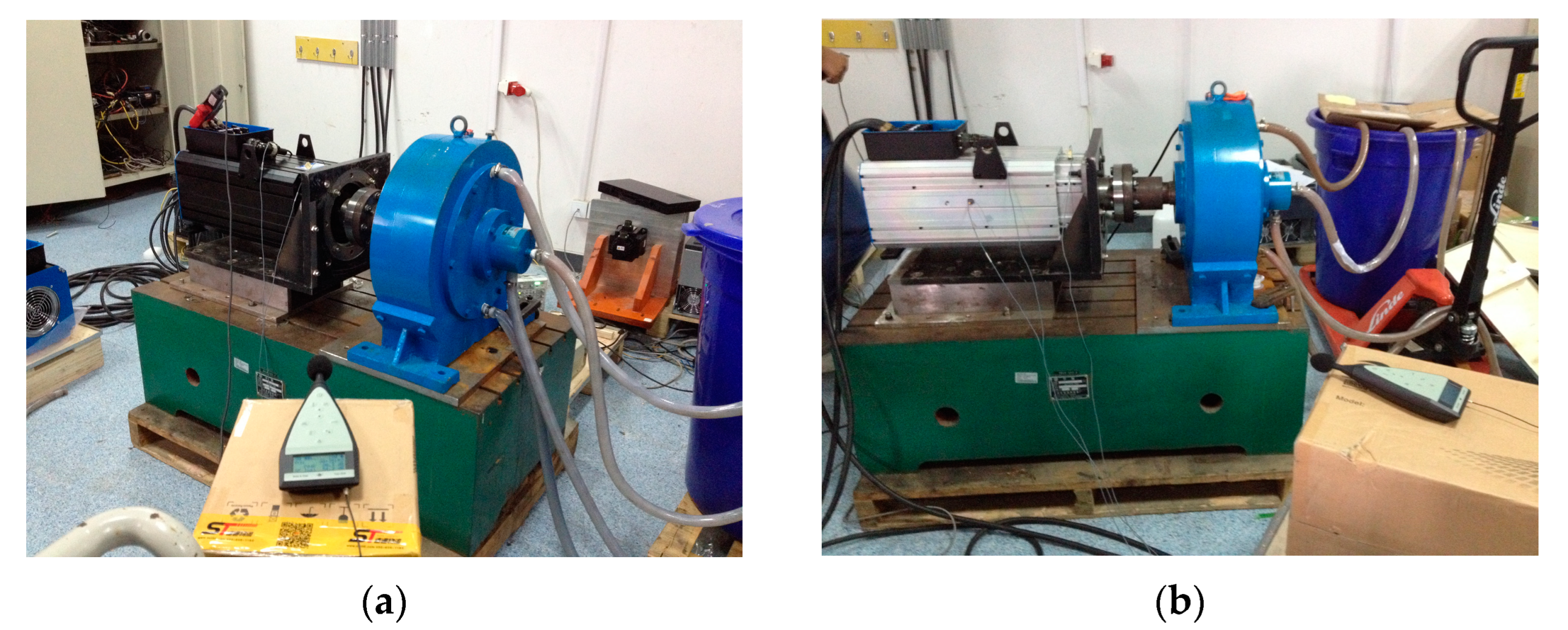
2.8. Vibration and Noise Experiments of the Two Types of Motor
In this section, vibration and the noise experiments for the structure of the SMPMM-UEPMS and for the structure of the SMPMM-EPMS were carried out. The test site is shown in
Figure 11. The method for obtaining the vibration and noise of the motor was the hemisphere method [
37]. The test motors were powered by a converter (model IS300). Three accelerometers (model B&K 4508B) were arranged at the front, middle, and rear ends of the motors, respectively, so that the vibration acceleration of the front, middle, and rear ends of the motors could be measured simultaneously. The sound level meter (model B&K2239) was positioned at 45° from the axis of the motor, 1 m away from the central axis of the motor, and 1 m above the ground.
2.9. Electromagnetic Force Wave of the Interaction of the Stator and the Rotor
According to the Maxwell tensor method, the radial electromagnetic force of the motor can be expressed as:
The magnetic field harmonic amplitude of the
vth flux density produced by the stator is expressed as
Brv. And the function of the air gap flux density at the stator surface of the motor can be expressed as follows:
The electromagnetic force density per unit area of the stator surface is expressed as follows:
It can be simplified as follows:
For an integer slot surface-mounted permanent magnet motor, the stator winding produces an odd number of field harmonic during the work and the frequency of the field harmonic can be expressed as:
For a fractional slot surface-mounted permanent magnet motor, the stator winding not only produces an odd number of field harmonics during the work but also it would bring an even order of field harmonics. According to the different parity of
d, the field harmonics have different expressions and
d can be determined by the following formula:
When
d is an even number, the frequency of the field harmonics, for a fractional slot surface-mounted permanent magnet motor, can be expressed as:
When
d is an odd number, the frequency of the field harmonics, for a fractional slot surface-mounted permanent magnet motor, can be expressed as:
where
,
Z is the number of slots,
m is the phase number and
p is the number of pole-pairs.
The order of the electromagnetic force wave and the harmonic distribution of the stator and the rotor on the surface of the stator are listed in
Table 1 and
Table 2.
By comparing
Table 1 and
Table 2, it can be seen that, compared with the SMPMM-EPM, SMPMM-UEPM increases the electromagnetic force wave of 1th, 2th, and 3th orders. The harmonic amplitude of the rotor magnetic field causing these electromagnetic force waves is small, but its effect on the vibration and noise of the motor cannot be ignored because of the relatively low order of the electromagnetic force waves.
3. Results and Discussion
This section lists the results calculated by the FEM and SSM of the two types of prototype. The motors were used in the actual application. One motor is the SMPMM-UEPMS, which has 7 identical small poles and 1 big pole, while the other motor is the SMPMM-EPMS, which has 8 identical magnet poles. They both adopt the control method of
id = 0 in vector control. The main design parameters of the prototypes are given in
Table 3.
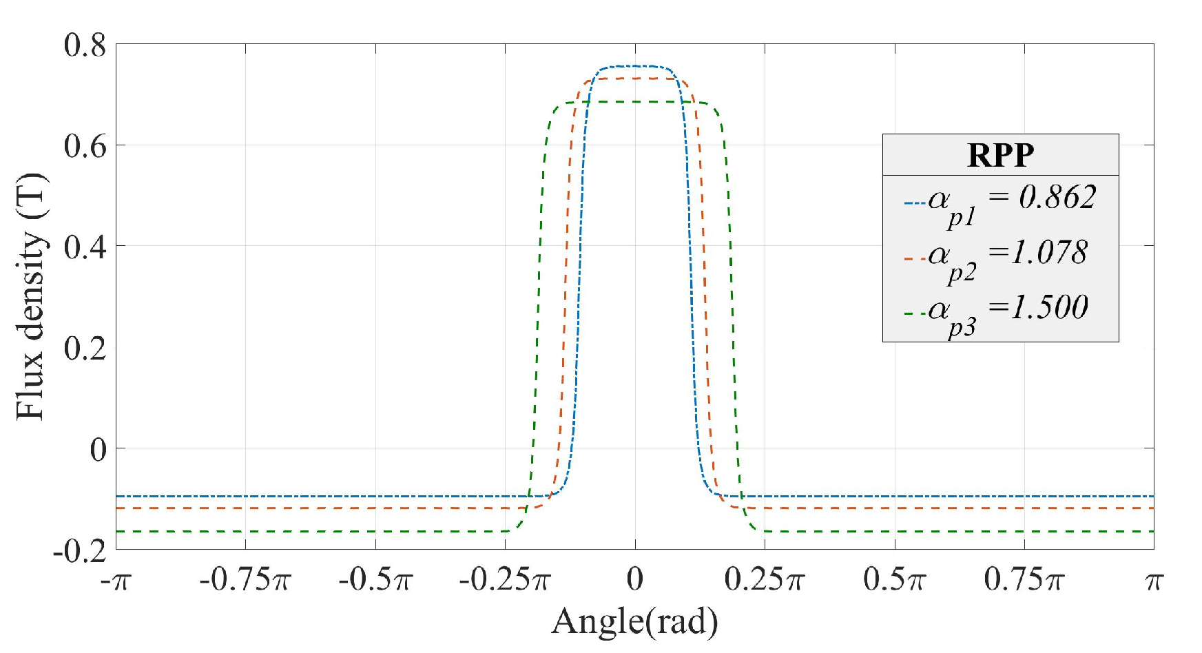
The RPP of the PM could be different, thus three groups of PMs with different RPPs, namely
αp1,
αp2, and
αp3, were selected to calculate the radial magnetic density at the surface of the stator i.e.,
r =
Rs; in this case, the remanence
Br is 1.22. The calculation results are shown in
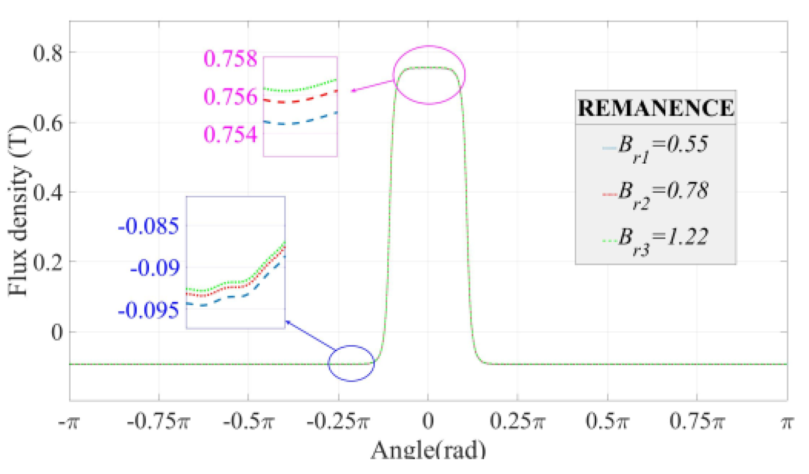
Figure 11. Similarly, the remanence of the PMs can be different. Therefore, three groups of PMs with different remanence coefficients, namely
Br1 = 0.55,
Br2 = 0.78, and
Br3 = 1.22, were taken into consideration for calculating the flux density in the air gap region; in this case, the RPP of the PMs were all 0.862. The calculation results are shown in
Figure 12. Meanwhile, the key data of
Figure 12 and
Figure 13 are listed in
Table 4.
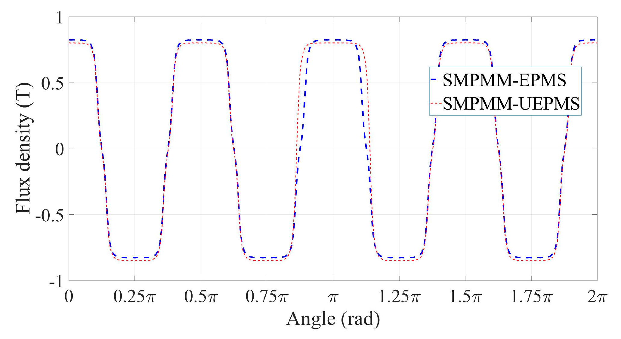
Table 4 shows that the magnetic field can be modulated by adjusting the RPP or the remanence of the PMs. Also, it shows that the magnetic field is more sensitive to the method of adjusting the RPP. By superimposing the magnetic field of each PM, calculated by the Fourier series, the whole magnetic field of the motor can be obtained. This is the Fourier series superimposing method, i.e., the SSM. By applying the SSM, the magnetic density waveforms of the two types of motors generated by the PMs were obtained. To be specific, firstly, the flux density waveforms generated by the large PM (RPP = 1.078) and the small PM (RPP = 0.862) were calculated, respectively, and the parameters used in the calculation are listed in
Table 1. After that, according to the mounting angles of different PMs, the obtained flux density waveforms were superimposed. Finally, the results of the radial flux density waveform, generated by the PMs of the SMPMM-EPMS and the SMPMM-UEPMS, were obtained using the superimposing method, and the results are shown in
Figure 14.
Comparing the curve of the SMPMM-EPMS with the curve of the SMPMM-UEPMS, the curve of the SMPMM-UEPMS shows an overall downward trend. This is due to the addition of PMs to the big pole increasing the whole area of the N-poles. Thus, this increases the magnetic flux flowing out of the N-poles. As the whole magnetic flux remains unchanged, i.e., the incoming magnetic flux is equal to the outgoing magnetic flux, this makes the magnetic flux flowing into the S-poles increase. While the area of the S-poles remains unchanged, the magnetic flux flowing into each S-pole increases. This makes the whole curve of the flux density of the SMPMM-UEPMS have a downward trend. For the curve of the SMPMM-EPMS, the maximum value of the flux density is 0.83, and the minimum value of the flux density is −0.83. Otherwise, for the curve of the SMPMM-UEPMS, the maximum value of the flux density is 0.80, and the minimum value of the flux density is −0.847.
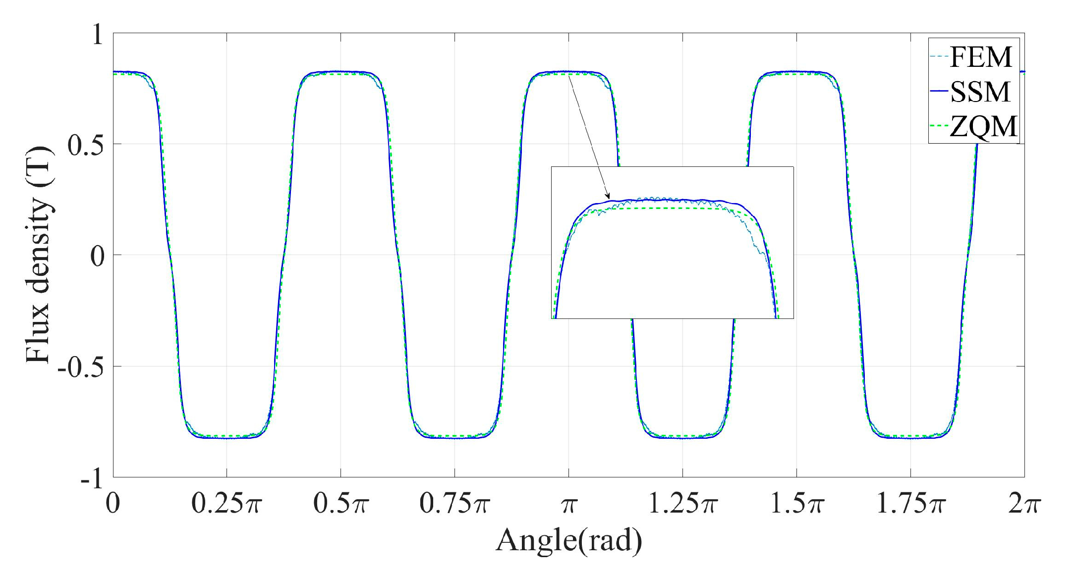
For the SMPMM-EPMS, three kinds of methods are used to calculate the radial component of the magnetic field distribution at the surface of the stator, i.e., the SSM, the ‘Z Q Zhu method (ZQM)’ in reference [
20], and the FEM.
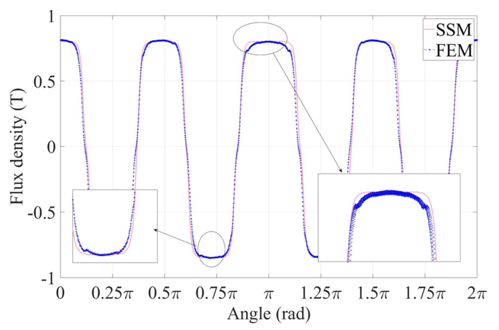
Figure 15 shows the results of the flux density of the SMPMM-EPMS, which was calculated using three methods. For the SSM curve, the maximum value of N-poles was 0.802, the minimum value of S-poles was −0.847, and for the FEM curve the maximum value for N-poles was 0.803, the minimum value for S-poles was −0.846, and the errors were 0.08% and 0.08%, respectively. The results of the three methods are almost identical. This indicates that the SSM can be used to analyze and calculate the magnetic flux density distribution at the surface of the stator. Nevertheless, for the SMPMM-UEPMS, only two methods are used to obtain the flux density, i.e., the SSM and the FEM. And the radial component results of the flux density calculated by the two methods are shown in
Figure 16.
Figure 16 shows that, for the SMPMM-UEPMS, the two methods had few errors. The max error is 3.9% at the edge of the big pole. Similarly, when calculating the magnet field distribution of the SMPMM-EPMS, there was also a large error at the edge of the PM. These errors were acceptable. According to these results, the SSM mentioned in this paper can be applied for the prediction of the open-circuit magnetic field distribution of the SMPMM-EPMS as well as the SMPMM-UEPMS. And the SSM can be applied to calculations of the SMPMM-EPMS, not only with one big magnet pole, but also with different numbers of big magnet poles or any combination of the big and small magnet poles. Moreover, the angle of the center line of the PMs of the topology model in this paper is uniformly distributed along the circumferential direction of the rotor surface. However, it could be different, and the SSM could be used to calculate the magnetic field distribution of the air gap region of these situations as well.
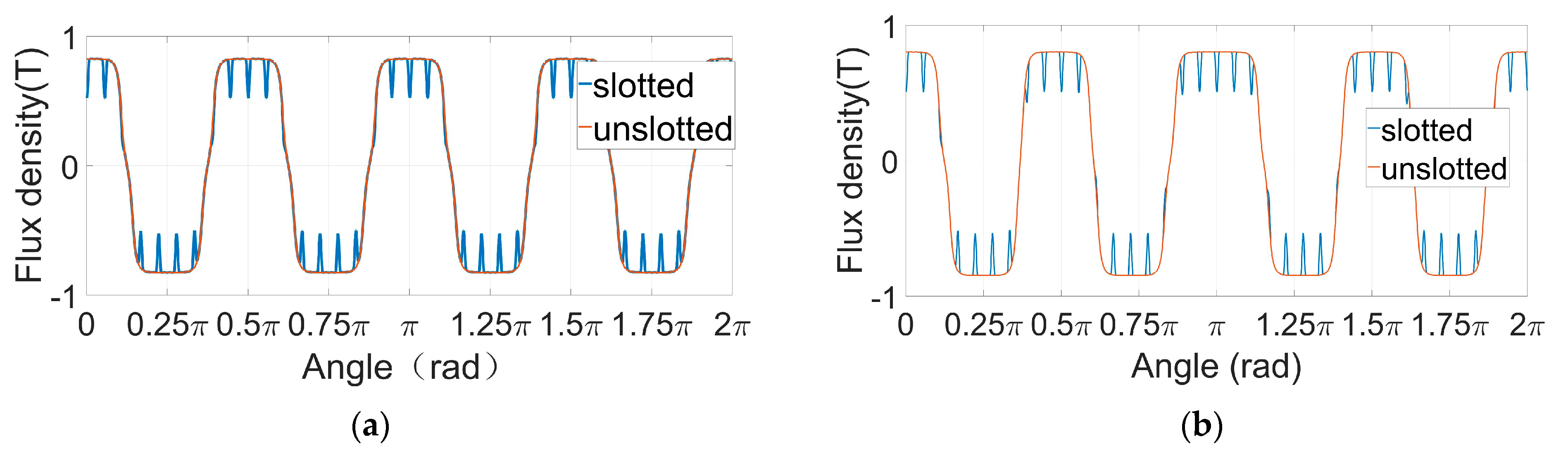
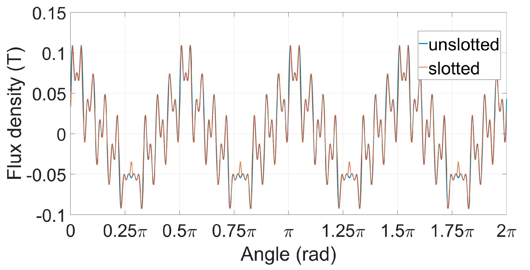
Figure 17 and
Figure 18 show the effect of grooving on the open-circuit magnetic field and the armature reaction field, respectively. As can be seen from the figures, the stator slotting will reduce the magnetic field generated by the rotor permanent magnet around the slot. The reason is that the stator slotting will increase the air gap width of the permanent magnet synchronous motor. The air gap width is inversely proportional to the flux density, so the radial flux density at the air gap will decrease. Stator grooving does not affect the overall distribution of the magnetic field generated by permanent magnets. This is because the magnetic field generated by permanent magnets will change periodically with the rotation of the rotor, while the stator groove is stationary and the influence of grooving will act on different positions of the rotor with the rotation of the rotor.
Figure 19 shows the results of the magnetic field distribution on the load of the motor with the structure of unequal magnetic poles. The load field of the SMPMM refers to the comprehensive magnetic field produced by the combined action of the load current applied in the stator winding of the SMPMM and the rotor permanent magnet. For the calculation of the load magnetic field of SMPMM, the effects of rotor permanent magnet, stator winding, and stator slot were considered comprehensively. The magnetic field generated by The rotor permanent magnet of a SMPMM rotates. The magnetic field generated by the stator windings will also change with time due to the three-phase alternating current. Therefore, the load magnetic field of a permanent magnet synchronous motor is superimposed by the magnetic field generated by the transient rotor permanent magnet and the magnetic field generated by the transient stator windings.
Figure 20 shows the noise spectra of the two types of motor when the rotation speed was 1000 r/min and with full load, and
Table 5 listed the test results of the vibration displacement and the noise frequency amplitude of the two types of motors when the rotation speed was 1000 r/min and with full load. Only the first 17th order of the noise frequency amplitude (NFA) and the vibration displacement (VD) are listed.
It can be seen from
Table 3 that the vibration displacement of each order of the SMPMM-UEPMS is smaller than that of the SMPMM-EPMS. Comparing the SMPMM-EPMS and the SMPMM-UEPMS, the noise frequency amplitude decreases, on the whole, for the SMPMM-UEPMS. However, the noise frequency amplitude of the SMPMM-EPMS is smaller than the SMPMM-UEPMS in some orders, such as in the 4th, 5th, 6th, and the 16th noise frequency amplitudes. Varying the permanent magnet configuration scheme is an effective method to reduce motor vibration and noise. The change in the configuration of the PMs makes the magnetic density distribution in the air gap region of the motor change. This change in air-gap magnetic density makes the electromagnetic force of the motor change. The air-gap magnetic density and the electromagnetic force could be related to the Maxwell tensor equation i.e.,
fr =
Br2/(2
μ0), and the electromagnetic force is one of the factors that affects the noise and the vibration of the motors, thus, the determining of the magnetic field distribution for the motor is one of the most important aspects of the basic work for suppressing the motor noise and vibration of a motor.
4. Conclusions
In this paper, we mainly applied the SSM to obtain the magnetic field distribution of the SMPMM-UEPMS, which few scholars have studied analytically before. Meanwhile, different permanent magnet configuration schemes changed the vibration and noise characteristics of the motor.
Specifically speaking, firstly, the general two-dimensional analytical topologies models viz. the SMPMM-UEPMS and the SMPMM-EPMS were established. The two types of the model had identical air-gap lengths, the same PM material, and identified ways of magnetizing PMs. Secondly, the magnetic flux density of the single PM was obtained by the Fourier series method. Then, by applying the superimposing method, the whole magnetic field distribution produced by the PMs was obtained. Thirdly, the FEM was used to predict the magnetic field distribution of the two types of motors, and the simulation results were compared with the predicted results of the SSM. Furthermore, for the SMPMM-EPMS, the ZQM was used to calculate the flux density, and the calculation results were compared with the results calculated by the SSM. Finally, the armature reaction field, the effect of the stator slotting, and the distribution of magnetic field when the motor had a load were taken into consider as well.
The SSM can intuitively obtain the magnetic field distribution without the conversion process such as that seen in the EMC method or EMCT method. The SSM can be applied for the calculation of the magnetic field distribution of the motor. Meanwhile, the calculation results of this paper provide a basis for the calculation of the electromagnetic force, the calculation of cogging torque, the calculation of the eddy current loss, and the analysis and suppression of the vibration and noise of the motor.
However, the topology model in this paper only considers the PMs with parallel-magnetized PMs instead of the other magnetization forms, i.e., radial magnetization or Halbach magnetization. In future work, PMs with other magnetization forms will be taken into consideration. Also, the magnetic saturation and eddy current loss will be taken into consideration as well. Moreover, based on the calculation results of this paper and the experimental results of vibration and noise, the suppression of the noise and vibration of the motor will be studied in the future.


