Abstract
A mechanically controlled switchable wideband frequency–selective rasorber/absorber, with the transmission window inside the absorption band, based on a frequency–selective surface and a rotatable metal plate, is presented in this paper. The absorption of the switchable rasorber/absorber is over 90%, from 3.9 GHz to 11.77 GHz, when the rotatable metal plate is parallel to the rest of the layers, and its transmission coefficient can reach up to 0.62 at 11.6 GHz, with the rotatable metal plate perpendicular to the rest of the layers. The mechanism of wideband absorption and transmission are explained by monitoring and analyzing the surface current distribution at the absorption and transmission frequencies. The control method is simple, reliable and accurate. It has application value in communication and radar stations.
1. Introduction
With the rapid development of radar detection systems, researchers have paid more and more attention to the stealth performance of weapons and equipment. The stealth performance of radome is different from general weapons and equipment, as it requires both transmission and stealth. Frequency–selective surfaces are often used in research on the transmission and stealth of radomes. However, the stealth of the frequency–selective surface only reflects the incident wave to other directions, so the frequency–selective surface has stealth effects only for single–station radar detection, and is not suitable for multi–station radar detection.
In order to resist the detection of multi–station radar, researchers have widely carried out the research on rasorbers/absorbers for absorbing and transmitting waves [1,2,3,4,5,6,7,8,9,10,11,12,13,14,15,16]. The rasorber/absorber is generally composed of an absorbing impedance layer and frequency–selective surface in order to achieve the effect of absorbing and transmitting the wave. In this respect, Chen Q et al. [4] designed a rasorber/absorber with the absorption loss layer loaded with resistor and frequency–selective surface as a transmitting layer, its absorption band from 3 GHz to 9 GHz, and the passband loss of less than 1 dB appears from 9.25 GHz to 9.8 GHz. Liu L G et al. [5] designed a rasorber/absorber by using resistors and frequency–selective surface. Its absorption band is from 3 GHz to 9 GHz and the passband frequency is 1 GHz, with a loss of less than 1 dB. The above–mentioned rasorbers/absorbers have the absorption band above or below the passband. In order to satisfy the requirement of communication security, some designs are put forward to achieve the transmission window inside the absorption band. In this respect, Shen Z and Yu Y et al. [7,8] designed three–dimensional (3–D) rasorbers/absorbers, which have smaller unitcell dimensions and stable angular performance, but their implementation was very complicated.
With the rapid development of tunable metamaterials, many designs of rasorbers/absorbers with tunable functions, which are applied in specific fields, have been proposed [12,17]. Y. Han et al. [12] designed a switchable rasorber/absorber with a simple structure. So far, most of the above–mentioned rasorbers/absorbers are based on switchable PIN diodes, and a large number of unit cells lead to their high power consumption and complex processing technology. Thus, the passive tunable rasorber/absorber has greater application prospects.
In this paper, we firstly present a mechanically controlled switchable wideband frequency–selective rasorber/absorber with the transmission window inside the absorption band, based on a frequency–selective surface and rotatable metal plate. The absorption of the switchable rasorber/absorber is over 90%, from 3.9 GHz to 11.77 GHz, when the rotatable metal plate is parallel to it, and its transmission is 0.62 at 11.6 GHz, with the rotatable metal plate perpendicular to the rest of the layers. Compared to the switchable rasorbers/absorbers based on PIN diodes [12,17], it has the advantages of a simple, reliable and accurate control method, with application values at the communication and radar station.
2. Model Design
Based on our former research and similar report on a rasorber/absorber [17,18], the designed mechanically controlled switchable wideband frequency–selective rasorber/absorber is shown in Figure 1. It consists of four layers: the top layer is a split metal ring () loaded with resistance film (), the second layer is an FR4 medium (, ), the third layer is a lossless bandpass layer, which is made with metal squared ring slots, and the bottom layer is a rotatable metal plate. The method of parameter scanning is adopted to optimize the size parameters of the unit cell. The optimized size parameters of the unit cell based on the best absorption and transmission performance are: a = b = 5 mm, r = 4 mm, c = 0.6 mm, d = 0.5 mm, e = f = 2.2 mm, g = 0.3 mm, t1 = t3 = t5 = 0.02 mm, t2 = 1 mm, and t4 = 7 mm. The rasorber/absorber can be fabricated through etching and resistive film–coating technology, where the practical difficulty lies in loading the resistive film.
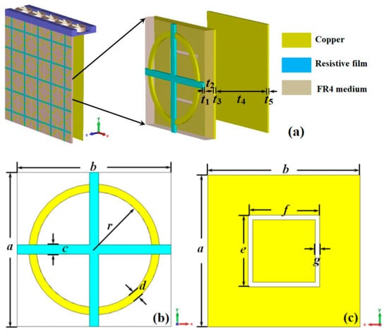
Figure 1.
The diagram of the switchable rasorber/absorber: (a) perspective view; (b) front view; (c) back view.
The commercial electromagnetic simulation software Microwave Studio CST is used to simulate the unit cell shown in Figure 1. During the simulation process, the boundary condition at the x and y direction is set as unit cell and the boundary condition at the z direction is set as open. The incident wave is along the z direction, and the electric and magnetic field of the incident wave is along the y and x direction, respectively. The floquet port analysis is followed to analyze the unit cell. The frequency solver is used to calculate the electromagnetic properties of the unit cell.
3. Results and Discussion
Figure 2 shows the reflection coefficient and the absorption of the switchable rasorber/absorber with the rotatable metal plate parallel to the rest of the layers. The absorption of the switchable rasorber/absorber is over 90%, from 3.9 GHz to 11.77 GHz. Figure 3 shows the reflection coefficient, transmission coefficient, and absorption of the switchable rasorber/absorber, with the rotatable metal plate perpendicular to the rest of the layers. At this condition, its transmission coefficient can reach up to 0.62 at 11.6 GHz. The above results show that the rasorber/absorber has the property of switchable wideband absorption/transmission and low power consumption, due to the simple, reliable and accurate mechanically controlled method.
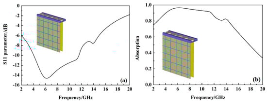
Figure 2.
The S11 parameter and absorption when the rotatable metal plate is parallel to the rest of the layers, (a) the S11 parameter; (b) the absorption.
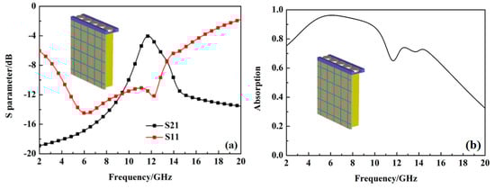
Figure 3.
The S parameters and absorption when the rotatable metal plate is perpendicular to the rest of the layers, (a) the S parameters; (b) the absorption.
The good impedance match with free space is the precondition for the realization of a metamaterial absorber. Based on the equivalent medium theory, the relative impedance of the switchable rasorber/absorber with free space when the rotatable metal plate is parallel to the rest of the layers is calculated by using the scattering parameter method [19], as shown in Figure 4. The real part of the relative impedance of the switchable rasorber/absorber with free space is close to 1, from 3.9 GHz to 11.77 GHz, which indicates that the switchable rasorber/absorber has achieved a good impedance match with free space. At this condition, the reflectivity is almost zone, and the bottom metal plate makes the transmittance close to zone; the lower reflectivity and transmittance make the absorption reach its maximum and realize the perfect absorption of the incident wave. The negative imaginary part of the relative impedance, from 3.9 GHz to 11.77 GHz, indicates that the switchable rasorber/absorber produces a huge loss in incident waves in the absorption band.
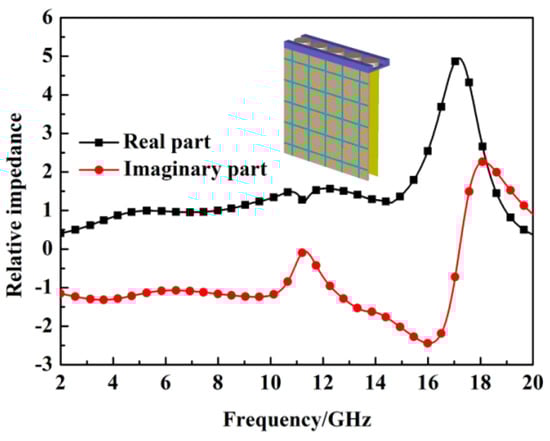
Figure 4.
The relative impedance when the rotatable metal plate is parallel to the rest of the layers.
In order to explore the mechanism of wideband absorption in the switchable rasorber/absorber when the rotatable metal plate is parallel to the rest of the layers, the surface current distribution at 11 GHz is monitored, as shown in Figure 5. The surface currents on the left and right sides of the top copper metal ring are parallel to the upward direction. This parallel current will cause the charges to accumulate alternately on the upper and lower parts of the copper ring and then result in electric resonance. The surface current on the metal substrate acts downwards, which is opposite to the surface current of the copper metal ring. The opposite surface current on the top copper metal ring and metal substrate form a current circuit, which can produce magnetic resonance [20,21,22,23]. The simultaneously produced electromagnetic resonance will lead to the high absorption of the incident wave. The resonant circuit structure of the switchable rasorber/absorber stays stable, and its impedance can match well with the free space at a wide range near the resonant frequency, and finally, lead to the wideband absorption of the incident wave [24].
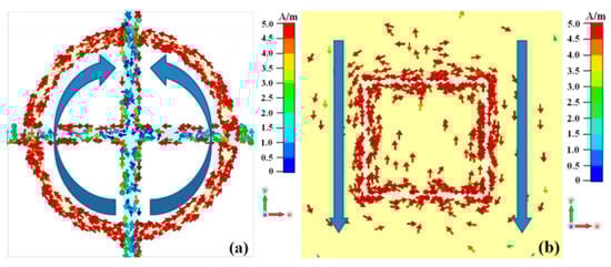
Figure 5.
The surface current distribution at 11 GHz when the rotatable metal plate is parallel to the rest of the layers, (a) the top copper metal ring, (b) the metal substrate.
The surface current distribution of the switchable rasorber/absorber at the transmission frequency of 10.31 GHz, when the rotatable metal plate is perpendicular to the rest of the layers, is shown in Figure 6. The surface currents on the left and right sides of the top copper metal ring are parallel to the upward direction. This parallel current will cause the charge to accumulate alternately in the upper and lower parts of the copper ring, and can also result in electric resonance. However, the surface current on the metal substrate is disordered. Therefore, the switchable rasorber/absorber cannot produce electromagnetic resonance at the transmission frequency of 10.31 GHz. This results in low absorption and high transmittance.
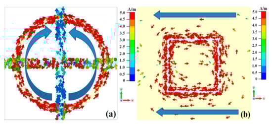
Figure 6.
The surface current distribution at 10.31 GHz when the rotatable metal plate is perpendicular to the rest of the layers, (a) the top copper metal ring, (b) the metal substrate.
The absorption and transmission coefficients of the switchable rasorber/absorber at different polarization angles are shown in Figure 7. The absorption of the switchable rasorber/absorber at different polarization angles is the same, but the transmission coefficient gradually decreases with the increasing polarization angle.
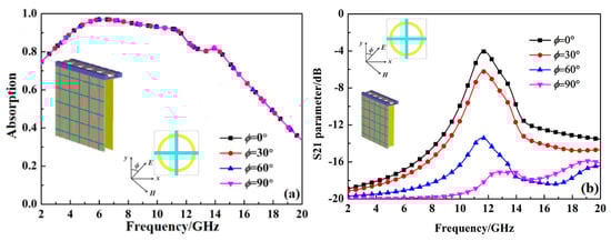
Figure 7.
The absorption and transmission coefficient at different polarization angles, (a) the absorption, (b) the transmission coefficient.
The absorption of the switchable rasorber/absorber at different incident angles when the rotatable metal plate is parallel to the rest of the layers is shown in Figure 8. The absorption gradually decreases with the increasing incident angle at TE mode. At TM mode, the absorption is almost the same with the increase in incident angle from 0° to 60°, but it suddenly decreases when the incident angle increases to 80°.
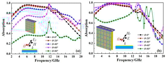
Figure 8.
The absorption at different incident angles when the rotatable metal plate is parallel to the rest of the layers, (a) TE mode, (b) TM mode.
The transmission coefficients of the switchable rasorber/absorber at different incident angles, when the rotatable metal plate is perpendicular to the rest of the layers, are shown in Figure 9. The transmission coefficient is very low at various incident angles at TE mode due to the polarization–sensitive property of the unit cell. At TM mode, the transmission coefficients gradually decrease with the increasing incident angle.
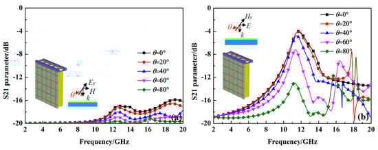
Figure 9.
The transmission coefficient at different incident angles when the rotatable metal plate is perpendicular to the rest of the layers, (a) TE mode, (b) TM mode.
The absorption and transmission coefficients of the switchable rasorber/absorber at different size parameters e are shown in Figure 10. The bandwidth of the switchable rasorber/absorber with the absorption over 90% gradually decreases with the increasing size parameter e; the transmission frequency gradually shifts to a lower frequency with the coefficient increasing when the size parameter e gradually increases. Figure 11 shows the absorption and transmission coefficient of the switchable rasorber/absorber at different square slot gap width g. The bandwidth of the switchable rasorber/absorber with the absorption over 90% and the transmission frequency is almost the same at different square slot gap width g.
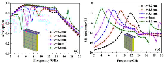
Figure 10.
The absorption and transmission coefficient at different size parameter e, (a) the absorption, (b) the transmission coefficient.
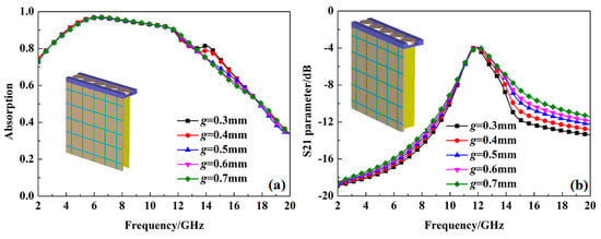
Figure 11.
The absorption and transmission coefficient at different size parameter g, (a) the absorption, (b) the transmission coefficient.
4. Conclusions
Based on the frequency–selective surface and rotatable metal plate, we designed a mechanically controlled switchable wideband frequency–selective rasorber/absorber with the transmission window inside the absorption band in this paper. The absorption of the switchable rasorber/absorber is over 90%, from 3.9 GHz to 11.77 GHz, when the rotatable metal plate is parallel to the rest of the layers, and its transmission coefficient can reach up to 0.62 at 11.6 GHz, when the rotatable metal plate is perpendicular to the rest of the layers. The mechanism of transmission and wideband absorption is analyzed according to the surface current distribution. The absorption of the switchable rasorber/absorber at different polarization angles stays the same, but its transmission coefficient decreases with the increase in the polarization angle. The absorption gradually decreases with the increase in the incident angle at TE mode. At TM mode, the absorption stays almost the same with the increase in incident angle from 0° to 60°, but it suddenly decreases when the incident angle increases to 80°. The transmission coefficient remains very low at different incident angles at TE mode. At TM mode, the transmission coefficients gradually decrease with the increase in incident angle. This has the advantages of a simple, reliable and accurate control method, with the application values at the communication and radar station.
Author Contributions
Software, Q.F.; investigation, Y.W.; resources, D.X.; project administration, L.W.; data curation, X.D.; investigation, Y.W. All authors have read and agreed to the published version of the manuscript.
Funding
The APC was funded by Hainan provincial natural science foundation of china (Granted number: 620MS062).
Data Availability Statement
The data that support the findings of this study are available from the corresponding author upon reasonable request.
Acknowledgments
The authors would like to thank the reviewers and the editor for their careful reviews and constructive suggestions to help us improve the quality of this paper.
Conflicts of Interest
The authors declare no conflict of interest.
References
- Costa, F.; Monorchio, A. A frequency selective radome with wideband absorbing properties. IEEE Trans. Antennas Propag. 2012, 60, 2740–2747. [Google Scholar] [CrossRef]
- Chen, Q.; Bai, J.; Chen, L. A miniaturized absorptive frequency selective surface. IEEE Antennas Wirel. Propag. Lett. 2015, 14, 80–83. [Google Scholar] [CrossRef]
- Zhou, H.; Yang, L.W.; Qu, S.B.; Wang, K.; Wang, J.F.; Ma, H.; Xu, Z. Experimental demonstration of an absorptive/ transmissive FSS with magnetic material. IEEE Antennas Wirel. Propag. Lett. 2014, 13, 114–117. [Google Scholar] [CrossRef]
- Chen, Q.; Yang, S.; Bai, J.; Fu, Y. Design of absorptive/transmissive frequency–selective surface based on parallel resonance. IEEE Trans. Antennas Propag. 2017, 65, 4897–4902. [Google Scholar] [CrossRef]
- Liu, L.G.; Li, Y.Q.; Meng, Q.Z.; Wu, W.W.; Mo, J.J.; Fu, Y.Q.; Yuan, N.C. Design of an invisible radome by frequency selective surface loaded with lumped resistors. Chin. Phys. Lett. 2013, 30, 064101. [Google Scholar] [CrossRef]
- Wang, Z.; Zeng, Q.; Fu, J.; Chen, W.; Bo, L.; Song, M.; Denidni, T.A. A high–transmittance frequency–selective rasorber based on dipole arrays. IEEE Access 2018, 6, 31367–31374. [Google Scholar] [CrossRef]
- Shen, Z.; Wang, J.; Li, B. 3–D frequency selective rasorber: Concept, analysis, and design. IEEE Trans. Microw. Theory Tech. 2016, 64, 3087–3096. [Google Scholar] [CrossRef]
- Yu, Y.; Shen, Z. 3D frequency selective rasorber with wide upper absorption band. IEEE Trans. Antennas Propag. 2017, 65, 4363–4367. [Google Scholar] [CrossRef]
- Zhang, Y.; Li, B.; Zhu, L.; Tang, Y.; Chang, Y.; Bo, Y. Frequency selective rasorber with low insertion loss and dual–band absorptions using planar slot line structures. IEEE Antennas Wirel. Propag. Lett. 2018, 17, 633–636. [Google Scholar]
- Shang, Y.; Shen, Z.; Xiao, S. Frequency–selective rasorber based on square–loop and cross–dipole arrays. IEEE Trans. Antennas Propag. 2014, 62, 5581–5589. [Google Scholar] [CrossRef]
- Omar, A.A.; Shen, Z.; Huang, H. Absorptive frequency–selective reflection and transmission structures. IEEE Trans. Antennas Propag. 2017, 65, 6173–6178. [Google Scholar] [CrossRef]
- Han, Y.; Che, W.; Xiu, X.; Yang, W.; Christopoulos, C. Switchable low–profile broadband frequency–selective rasorber/absorber based on slot arrays. IEEE Trans. Antennas Propag. 2017, 65, 6998–7008. [Google Scholar] [CrossRef]
- Huang, H.; Shen, Z. Absorptive frequency–selective transmission structure with square–loop hybrid resonator. IEEE Antennas Wirel. Propag. Lett. 2017, 16, 3212–3215. [Google Scholar] [CrossRef]
- Xiu, X.; Che, W.; Han, Y.; Yang, W. Low–profile dual–polarization frequency–selective rasorbers based on simple–structure lossy cross–frame elements. IEEE Antennas Wirel. Propag. Lett. 2018, 17, 1002–1005. [Google Scholar] [CrossRef]
- Chen, Q.; Sang, D.; Guo, M.; Fu, Y. Frequency–selective rasorber with interabsorption band transparent window and interdigital resonator. IEEE Trans. Antennas Propag. 2018, 66, 4105–4114. [Google Scholar] [CrossRef]
- Zhang, K.; Jiang, W.; Gong, S. Design bandpass frequency selective surface absorber using LC resonators. IEEE Antennas Wirel. Propag. Lett. 2017, 16, 2586–2589. [Google Scholar] [CrossRef]
- Qian, G.X.; Zhao, J.M.; Ren, X.M.; Chen, K.; Jiang, T.; Feng, Y.J.; Liu, Y. Switchable broadband dual–polarized frequency–selective rasorber/absorber. IEEE Antennas Wirel. Propag. Lett. 2019, 18, 2508–2512. [Google Scholar] [CrossRef]
- Wang, L.S.; Xia, D.Y.; Fu, Q.H.; Ding, X.Y.; Wang, Y. An electrically switchable wideband metamaterial absorber based on graphene at P band. Open Phys. 2021, 19, 460–466. [Google Scholar] [CrossRef]
- Smith, D.R.; Schultz, S. Determination of effective permittivity and permeability of metamaterials from reflection and transmission coefficients. Phys. Rev. B 2002, 65, 195104. [Google Scholar] [CrossRef] [Green Version]
- Shen, X.P.; Cui, T.J.; Ye, J.X. Dual band metamaterial absorber in microwave regime. Acta Phys. Sin. 2012, 61, 058101. [Google Scholar] [CrossRef]
- Xie, J.W.; Quader, S.; Xiao, F.J.; He, C.; Liang, X.L.; Geng, J.P.; Jin, R.H.; Zhu, W.R.; Rukhlenko, I.D. Truly all–dielectric ultra–broadband metamaterial absorber: Water–based and ground–free. IEEE Trans. Antennas Propag. 2019, 18, 536–540. [Google Scholar] [CrossRef]
- Zhang, J.; Li, Z.F.; Shao, L.D.; Zhu, W.R. Dynamical absorption manipulation in a graphene–based optically transparent and flexible metasurface. Carbon 2021, 176, 374–382. [Google Scholar] [CrossRef]
- Quader, S.; Akram, M.R.; Xiao, F.J.; Zhu, W.R. Graphene based ultra–broadband terahertz metamaterial absorber with dual–band tenability. J. Opt. 2020, 22, 095104. [Google Scholar] [CrossRef]
- GUC; Qu, S.B.; Pei, Z.B.; Xu, Z.; Lin, B.Q.; Zhou, H.; Bai, P.; Gu, W.; Peng, W.D.; Ma, H. Design of a wide–band metamaterial absorber based on resistance films. Acta Phys. Sin. 2011, 60, 087802. [Google Scholar]
Publisher’s Note: MDPI stays neutral with regard to jurisdictional claims in published maps and institutional affiliations. |
© 2022 by the authors. Licensee MDPI, Basel, Switzerland. This article is an open access article distributed under the terms and conditions of the Creative Commons Attribution (CC BY) license (https://creativecommons.org/licenses/by/4.0/).