Abstract
The DC microgrid does not need to consider frequency when accessing distributed energy, but the distributed energy access port does not have inertia and damping characteristics, so there are problems of voltage instability and power fluctuation. In this paper, the bidirectional DC–DC converter is the main object; based on the virtual synchronous generator (VSG) control strategy, the inertia regulation is added to adjust the bus voltage dynamically. In addition, a balancing strategy is proposed to ensure the balanced distribution of the state of charge (SOC) and power for multiple batteries. Finally, a simulink is built to prove the viability and availability of the VSG control strategy.
1. Introduction
The consumption of fossil energy, mainly consisting of coal, oil, and natural gas, has increased dramatically with the development of society, resulting in an increasing problem of energy demand. Therefore, it is necessary to use new energy to generate electricity to meet the energy demand. With the development of distributed control technology [1,2], distributed generation technology is becoming widely used in microgrids. Distributed generation technology is the main path toward new energy generation, which mainly relies on a distributed power supply. However, the performance requirements of the distribution network have become stricter with the grid connection operation of distributed generation (DG) technology. The security and stability of DC microgrids composed of distributed generations, energy storage system units, and loads have become a research hotspot in recent years. The typical DC microgrids with DESS is shown in Figure 1. The DC microgrid loses stability as a large number of distributed systems are linked [3]. Therefore, maintaining the stability of the DC bus voltage has become one of the main tasks of microgrid research [4]. In [3], the large signal stability of inverters in a DC microgrid was discussed to solve the instability. In [4], the stability of the microgrid was ensured by studying a hybrid energy storage system.
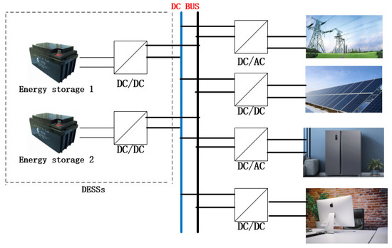
Figure 1.
Typical DC microgrids with DESS.
Due to the low inertia of DC microgrids, the DC bus voltage fluctuates from its steady value with frequent variation in loads and the intermittent generation of renewable power generators (RPGs). There are many ways to maintain bus voltage stability, such as damping compensation [5] or additional energy storage units [6]. However, none of these methods has improved the inertia; so, the effect of changing the performance of the DC microgrid has been limited. Therefore, the key to adjusting the DC bus voltage is to control the power electronics converters to enhance the inertia in DC microgrids. In order to improve the stability of a DC microgrid, virtual inertial control (VIC) technology has been applied to inverters. In [7], a virtual inertia control technology was introduced for DC bus voltage control to adjust the bus voltage and emulate inertia. The DC bus voltage control unit consisted of a bidirectional DC–DC converter (B-DC) and an inverter. In [8], a controller was designed to realize the virtual inertial control of the microgrid. However, their control depended on voltage synchronization based on a phase-locked loop when the above methods were connected to the power grid. In order to avoid the above influence, the concept of a virtual synchronous generator (VSG) has been proposed.
The VSG control strategy simulates the characteristics of synchronous generators, so that the distributed converters have inertia and damping, and the distributed power generation units can support the system’s frequency and voltage [9,10,11]. In [12], an improved VSG control algorithm was proposed, which solved the problem of the large frequency oscillation caused by the system parameters in the VSG control. The theoretical proof showed that the grid-connected VSG could maintain stability under very weak grid-connected conditions in [13]. In [14], the adaptive virtual impedance control strategy was proposed to accelerate the active power adjustment process of the VSG system, which was helpful to complete the primary frequency modulation and improve the inertia adjustment ability. Due to the contradiction between the steady-state deviation of the VSG active power and dynamic shock regulation, an improved VSG virtual inertia control strategy was proposed to improve the dynamic characteristics of active power and maintain the steady-state characteristics [15]. The dynamic characteristics of a microgrid were improved through the improvement of the VSG virtual inertial control strategy [16]. In [17], a VSG control method based on adaptive virtual impedance was proposed, which relieved the output impedance of the converter and ensured the sharing of reactive power.
On the other hand, because the initial value of the SOC for each battery in the energy storage system is different, the power and frequency provided for the microgrid easily fluctuate, which reduces the stability of microgrid operation. The research on the SOC balance in the batteries of a microgrid has also become a research hotspot in recent years [18,19]. When the SOC of the batteries are balanced, the maximum capacity support can be achieved for DGs [20,21,22]. In [23], the current between the energy storage units was distributed in proportion to the capacity, and the same sag curve was defined. In [24], an adaptive droop control scheme was proposed to balance the SOC. In the charging mode, the droop coefficient proportional to the nth order of the state of charge was adopted, and in the discharge mode, the droop coefficient inversely proportional to the nth order of the state of charge was adopted. A completely decentralized control method was proposed in [25], which eliminated the need for central controllers and communication links. In [26], a new power allocation method for an energy storage unit was proposed, which not only balanced the SOC but also realized the control of the required power. In [27], a virtual DC machine control strategy was proposed to balance the SOC of the energy storage unit while improving the inertia of the microgrid. Based on the above analysis, we propose the SOC-based VSG control strategy to balance the power and SOC of multiple energy storage units while improving the inertia of the DC microgrid, so as to improve the stability of the DC microgrid.
The major contributions of this paper are as follows: 1. An improved control strategy of a virtual synchronous generator for a DC–DC converter of a battery energy storage unit is proposed, which dynamically adjusts the bus voltage to the desired stability value by combining the voltage variation rate and inertia coefficient. Moreover, the small signal model is established to consider the dynamic characteristics of the proposed control and ensure the stability of the system. 2. In order to solve the problem of the early discharge of batteries with a low initial charge state due to the unreasonable power distribution among batteries, the SOC balance strategy for adjusting the battery power balance for multiple batteries is proposed, which further guarantees the stability of the bus voltage and the microgrid system. Compared with [27], we apply the SOC balanced distribution method to the DC microgrid based on VSG control, which has a better effect on restraining the bus voltage fluctuation.
The remaining sections are organized as follows: the DC–DC VSG control strategy is introduced in Section 2. In Section 3, we introduce the SOC power balance distribution strategy. The feasibility of the results is verified by simulation in Section 4. Finally, the conclusions and plans for future research are drawn in Section 5.
2. DC–DC Virtual Synchronous Generator Control Strategy
In this section, the traditional VSG control strategy is improved, and the inertia coefficient is combined with the voltage change rate to suppress the bus voltage fluctuation. Moreover, the small signal model is established to analyze the stability of small interference.
2.1. DC Microgrid Topology
Figure 2 is a structure diagram of a DC microgrid, which contains a B-DC. The DC microgrid is mainly composed of distributed energy storage, loads, and converters. The main circuit diagram of the B-DC is as follows.
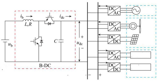
Figure 2.
Structure Diagram of a DC Microgrid with a B-DC.
As shown in Figure 2, L and R are the inductors and resistors, respectively. is the voltage of the energy storage system, is the DC bus voltage, is the current of inductance and resistance, and is the current of the converter. The B-DC is directly linked to the DC bus to ensure the stability of the bus voltage and the balance of power. The topology shown in the figure makes it easier to expand the DC microgrid.
2.2. Virtual Synchronous Generator
The VSG mainly simulates the inertia and damping of the synchronous generator; it can ensure the stable operation of a microgrid. The formula of the mechanical motion of the synchronous generator rotor is expressed as:
where J is the moment of inertia of the synchronous generator, is the rotor angular velocity, is the rated angular velocity, is the mechanical torque, is electromagnetic torque, and is the damping coefficient.
The rotor motion equation can be expressed as:
where is the mechanical power, and is the electromagnetic power.
When the power of the synchronous generator is unbalanced, the output frequency remains stable because of the inertia characteristics of the synchronous generator rotor. In addition, the existence of the damping characteristics enables the synchronous generator to suppress the power fluctuation.
The essence of the virtual synchronous control strategy is to simulate the distributed inverter power supply as a synchronous generator through the control strategy, so that the distributed inverter power supply can obtain the characteristics similar to the synchronous generator. The VSG is composed of energy storage and an inverter. One side of the VSG can be linked to a DC bus or distributed generator, and the other side can be connected to a public grid or a microgrid. The inverter simulates the inertia and damping characteristics of the synchronous generator.
In [28], Equation (1) was analogized to enhance the inertia of the microgrid and to restrain the DC bus voltage fluctuation. The equation is as follows:
where is the virtual capacitance, is the DC voltage reference value, is the rated value of the DC bus voltage, is the droop coefficient, and is the dc output current reference.
2.3. Improved Virtual Synchronous Generator
Although the VSG control can alleviate the impact of sudden load changes on a DC microgrid, when a power supply or load power disturbance occurs, the rate of voltage change is too large due to the power fluctuation. Therefore, it is possible to consider using the rate of voltage change caused by a power disturbance to adjust the inertial parameters in real time so as to avoid the voltage rise and fall.
On the basis of the VSG, the inertia coefficient is introduced to solve the problem in which the voltage difference introduced into the virtual synchronous generator leads to the system’s stability degradation; it alleviates the frequent voltage and power mutations in a microgrid system. The inertia coefficient is combined with the rate of change of the DC bus voltage in the system to achieve the flexible adjustment of various parameters of the VSG. In this paper, the improved VSG control method is proposed:
where is the inertia coefficient, is the DC bus voltage, and is the DC output current.
The improved VSG control strategy suppresses the bus voltage fluctuations by combining the voltage change rate and the inertia coefficient.
2.4. Small Signal Model
The B-DC proposed in this article is a BUCK-BOOST circuit, and its circuit diagram is shown in Figure 3.
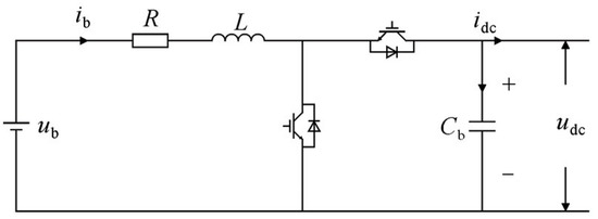
Figure 3.
Buck-Boost Circuit Diagram.
From the above figure, a small signal model of the B-DC circuit was built according to Kirchhoff’s law of current and voltage to study the stability of the model. Its mathematical model expression is:
where C is the capacitor; is the DC bus voltage; n is the duty cycle; is the battery current; is the output current; L is the inductance; and is the battery voltage.
Equations (5) and (6) are linearized near steady-state values, and by Laplace transform we can obtain:
From Equations (7) and (8), the relationship between the variables can be obtained as follows:
where is the ratio of a small disturbance of the battery current to a small disturbance of the output current, is the transfer function of the current loop, is the ratio of the small disturbance of the bus voltage to the small disturbance of the duty cycle, is ratio of the small disturbance of the bus voltage to the small disturbance of the output current, which are the transfer functions between the variables, and is the feedforward compensation. is the PI voltage regulator, which can realize no difference adjustment between and . is the PI current regulator, which can realize no difference adjustment between and . is the small disturbance of the corresponding physical quantity.
According to the relationship between the variables, we can build a B-DC control block diagram under the control of a VSG, as shown in Figure 4.
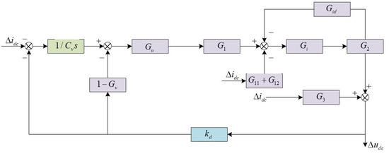
Figure 4.
B-DC Small Signal Control Block Diagram Under VSG Control.
Small signal analysis is used for stability analysis near the stable operating point affected by the small interference.
Each unit is connected to the DC bus, and the proposed distribution strategy is related to the DC bus voltage; so, ensuring the stability of the DC bus voltage is a necessary and sufficient condition for achieving SOC balancing.
3. SOC Balancing Strategy
The unbalanced output power of batteries often results in unstable bus voltage. The system cannot operate steadily at the rated voltage because of the existence of multiple batteries in the system. Therefore, this article further carried out SOC power allocation to the battery. The control block diagram of the SOC power allocation strategy under the control of the VSG is shown in Figure 5.
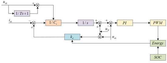
Figure 5.
VSG SOC Power Distribution Control Block Diagram.
The power that the energy storage unit has to bear when the microgrid is operating is calculated as:
where is the power to be assumed by the battery; is the load current; is the load voltage; and is the output power of the photovoltaic panel.
In order to stabilize the DC microgrid voltage within the allowable range, a power compensation link was set up in the energy storage system. The compensation power undertaken by the battery is:
where is the compensation power to be undertaken by the battery, and is the output current of the i-th battery.
From Equations (14) and (15), we can obtain the total power that the battery has to bear as:
Based on the above, we propose the SOC power balanced strategy:
where is the SOC of the i-th battery, is the remaining capacity of the i-th battery, is the power allocated for the i-th battery, is the initial state of charge; is the output current, and and represent the minimum and maximum SOC of the batteries, respectively.
4. Simulation Results
In order to test the feasibility and effectiveness of the proposed approach, we chose the rated value of the DC bus voltage V and the droop control coefficient on the basis of the actual system of a microgrid in conjunction with [25]. The simulation model of a DC microgrid was established in Matlab/Simulink. The simulation parameters are shown in Table 1.

Table 1.
Model parameters.
Figure 6 shows the voltage stability waveform of introducing on the basis of VSG control, in which Figure 6a is the waveform of the bus voltage, Figure 6b is the waveform of the bus voltage deviation, and Figure 6c is the waveform of the bus compensation voltage. From Figure 6a, it can be seen that the bus voltage quickly regulated to the rated voltage within 0.5 s. From Figure 6b, the voltage deviation was 50 V, when the bus voltage was 350 V. Then, the voltage deviation also became zero, when the bus constant voltage was stabilized at the rated value. Therefore, we can conclude that the VSG control strategy proposed in this paper can quickly regulate the DC bus voltage to the rated value.
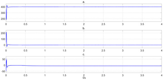
Figure 6.
Voltage waveform. (a) Bus voltage. (b) Voltage deviation. (c) Compensation voltage.
We chose the initial SOC values of two batteries as = 70% and = 60% for simulation verification, respectively. Figure 7 shows the SOC curve of the two batteries. From Figure 7, we see that the values of and were consistent at 1.5 s, when the initial values were different. Then, the same value was used until reaching SOC = 100% at 3.6 s. Figure 8 shows the deviation of and . From Figure 8, we see that the deviation of and was zero at 1.5 s and was maintained.
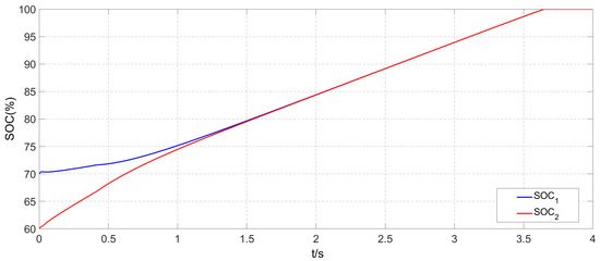
Figure 7.
SOC Change.
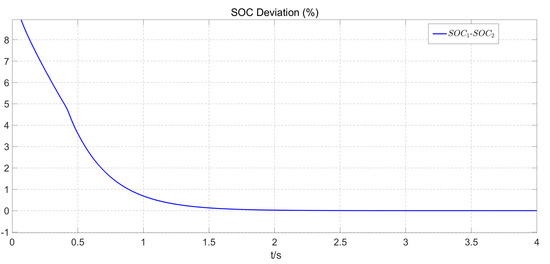
Figure 8.
SOC Deviation.
The power output curves of the two batteries are shown in Figure 9. The power output was balanced at 1.5 s. From Figure 8 and Figure 9, we can conclude that the proposed balanced strategy not only ensured that the SOC values of the two batteries were balanced to the same value, but also the output power was equally distributed.
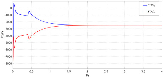
Figure 9.
Power Balance.
Based on the above analysis, the proposed control method can not only regulate the DC bus voltage to the rated value but also ensure the balanced distribution of the SOC and the power in the energy storage system. Under the effect of this control method, the inertia of the DC microgrid system was improved, and it restrained the fluctuation of the bus voltage and ensured the stability of the DC microgrid when the power of the system changed suddenly. Moreover, the power distribution method proposed can enable batteries with a larger SOC to bear more power, to achieve the balance of the SOC among batteries. Meanwhile, it can reduce the discharge of the battery with a low SOC and prolong the service life of the battery.
5. Conclusions
In this paper, the proposed control strategy was shown to restrain the fluctuation of the bus voltage and ensure the transient stability of the DC microgrid, when the power of the DC microgrid changed suddenly.
Meanwhile, a new SOC power balance distribution strategy was proposed to ensure that the power of two storage batteries could be quickly and effectively distributed, which ensured the stable operation of the microgrid. Through this distribution strategy, the power of the multiple energy storage units and the SOC eventually became equal.
The control method proposed by us is only applicable to a DC microgrid. The frequency and phase changes would need to be considered in an AC microgrid; so, the method proposed in this paper is not valid for an AC microgrid. In the future, we hope to study the power sharing of multicomponent distributed energy storage units based on the concept of multiagent consensus and apply it to an AC microgrid. Moreover, the voltage and frequency in AC microgrids are also important issues to be considered. Therefore, we plan an in-depth study on the voltage regulation and frequency regulation in an AC microgrid.
Author Contributions
Conceptualization, H.Z. and X.C.; methodology, H.Z., C.W. and X.C.; software, H.Z. and X.C.; investigation, H.Z., X.C., C.W., X.L. and J.Q.; writing—original draft preparation, H.Z.; funding acquisition, X.C. All authors have read and agreed to the published version of the manuscript.
Funding
This work was supported by the National Natural Science Foundation of China under (Grant Nos. 62173175, 61877033, 61903170, 61833005), the Natural Science Foundation of Shandong Province under (grants Nos. ZR2019BF045, ZR2019MF021, ZR2019QF004), the University-Industry Collaborative Education Program (Grant No. 201801256007), and the Horizontal Scientific Research Project of Linyi University under (Grant Nos. HX180050, HX2000032).
Institutional Review Board Statement
Not applicable.
Informed Consent Statement
Not applicable.
Data Availability Statement
Not applicable.
Conflicts of Interest
The authors declare no conflict of interest.
References
- Wang, C.; Chen, X.; Cao, J.; Qiu, J.; Liu, Y.; Luo, Y. Neural Network-Based Distributed Adaptive Pre-Assigned Finite-Time Consensus of Multiple TCP/AQM Networks. IEEE Trans. Circuits Syst. I Regul. Pap. 2021, 68, 387–395. [Google Scholar] [CrossRef]
- Hu, S.; Chen, X.; Qiu, J.; Zhao, F.; Jiang, X.; Du, Y. Dynamic Event-triggered Bipartite Consensus of Multi-agent Systems with Estimator and Cooperative-Competitive Interactions. IEEE Trans. Circuits Syst. II Express Briefs 2022, 69, 3309–3313. [Google Scholar]
- Gui, Y.; Han, R.; Josep, M.G.; Juan, C.V.; Wei, B.; Wonhee, K. Large-Signal Stability Improvement of DC-DC Converters in DC Microgrid. IEEE Trans. Energy Convers. 2021, 36, 2534–2544. [Google Scholar] [CrossRef]
- Ujjal, M.; Wang, B.; Zhang, X.; Gooi, H.B.; Liu, Y.; Abhisek, U. Joint Control of Three-Level DC–DC Converter Interfaced Hybrid Energy Storage System in DC Microgrids. IEEE Trans. Energy Convers. 2019, 34, 2248–2257. [Google Scholar]
- Muhammad, T.F.; Muhammad, M.K.; Xu, J.; Muhammad, A.; Salman, H.; Khurram, H.; Tang, H. Capacitor Voltage Damping Based on Parallel Feedforward Compensation Method for LCL-Filter Grid-Connected Inverter. IEEE Trans. Ind. Appl. 2020, 56, 837–849. [Google Scholar]
- Xie, Q.; Zhao, R.; Tang, M.; Hu, S.; Xu, H.; Tan, X.; Li, Y.A. DC Voltage Sag Compensator Based on SMES-Battery Hybrid Energy Storage. IEEE Trans. Appl. Supercond. 2021, 31, 1–5. [Google Scholar] [CrossRef]
- Soumya, S.; Jyoti, P.M.; Binoy, K.R. Implementation of a virtual inertia control for inertia enhancement of a DC microgrid under both grid connected and isolated operation. Comput. Electr. Eng. 2019, 76, 283–298. [Google Scholar]
- Yan, W.; Cheng, L.; Yan, S.; Gao, W.; Gao, D. Enabling and Evaluation of Inertial Control for PMSG-WTG Using Synchronverter with Multiple Virtual Rotating Masses in Microgrid. IEEE Trans. Sustain. Energy 2020, 11, 1078–1088. [Google Scholar] [CrossRef]
- Samanta, S.; Mishra, J.P.; Roy, B.K. AC load bus frequency control of a DC microgrid based on DC voltage regulation using inertia emulation and economic power management. IET Gener. Transm. Distrib. 2019, 13, 5117–5128. [Google Scholar] [CrossRef]
- Yang, Y.; Xu, J.; Li, C.; Zhang, W.; Wu, Q.; Wen, M.; Frede, B. A New Virtual Inductance Control Method for Frequency Stabilization of Grid-Forming Virtual Synchronous Generators. IEEE Trans. Ind. Electron. 2023, 70, 441–451. [Google Scholar] [CrossRef]
- Li, C.; Yang, Y.; Cao, Y.; Aleshina, A.; Xu, J.; Blaabjerg, F. Grid Inertia and Damping Support Enabled by Proposed Virtual Inductance Control for Grid-Forming Virtual Synchronous Generator. IEEE Trans. Power Electron. 2023, 38, 294–303. [Google Scholar] [CrossRef]
- Zhang, L.; Zheng, H.; Wan, T.; Shi, D.; Cai, J. An integrated control algorithm of power distribution for islanded microgrid based on improved virtual synchronous generator. IET Renew. Power Gener. 2021, 15, 2674–2685. [Google Scholar] [CrossRef]
- Du, W.; Dong, W.; Wang, Y.; Wang, H. Small-disturbance stability of a wind farm with virtual synchronous generators under the condition of weak grid connection. IEEE Trans. Power Syst. 2021, 36, 5500–5511. [Google Scholar] [CrossRef]
- Ren, M.; Li, T.; Shi, K.; Xu, P.; Sun, Y. Coordinated control strategy of virtual synchronous generator based on adaptive moment of inertia and virtual impedance. IEEE J. Emerg. Sel. Top. Circuits Syst. 2021, 11, 99–110. [Google Scholar] [CrossRef]
- Xu, H.; Yu, C.; Liu, C.; Wang, Q.; Zhang, X. An improved virtual inertia algorithm of virtual synchronous generator. J. Mod. Power Syst. Clean Energy 2020, 8, 377–386. [Google Scholar] [CrossRef]
- Nian, H.; Jiao, Y. Improved Virtual Synchronous Generator Control of DFIG to Ride-Through Symmetrical Voltage Fault. IEEE Trans. Energy Convers. 2020, 35, 672–683. [Google Scholar] [CrossRef]
- Liang, X.; Andalib-Bin-Karim, C.; Li, W.; Mitolo, M.; Shabbir, M.N.S.K. Adaptive Virtual Impedance-Based Reactive Power Sharing in Virtual Synchronous Generator Controlled Microgrids. IEEE Trans. Ind. Appl. 2021, 57, 46–60. [Google Scholar] [CrossRef]
- Liu, Y.; Wang, H.; Zhang, Q. Power distribution strategy based on state of charge balance for hybrid energy storage systems in all-electric ships. J. Power Electron. 2021, 21, 1213–1224. [Google Scholar] [CrossRef]
- Hoang, K.D.; Lee, H.H. State of charge balancing for distributed battery units based on adaptive virtual power rating in a DC microgrid. J. Electr. Eng. Technol. 2020, 15, 2121–2131. [Google Scholar] [CrossRef]
- Wang, L.; Lin, F.; Chen, W. Hybrid control of networked battery systems. IEEE Trans. Sustain. Energy 2019, 10, 1109–1119. [Google Scholar] [CrossRef]
- Qi, N.; Fang, W.; Wang, W. SOC balancing method for energy storage systems in DC microgrids using simplified droop control. J. Power Electron. 2021, 21, 1200–1212. [Google Scholar] [CrossRef]
- Cao, Y.; Abu Qahouq, J.A. Hierarchical SOC Balancing Controller for Battery Energy Storage System. IEEE Trans. Ind. Electron. 2021, 68, 9386–9397. [Google Scholar] [CrossRef]
- Eydi, M.; Ghazi, R. Control strategy to improve load/power sharing, DC bus voltage restoration, and batteries SOC balancing in a DC microgrid. IET Renew. Power Gener. 2020, 14, 2668–2679. [Google Scholar] [CrossRef]
- Belal, E.K.; Yehia, D.M.; Azmy, A.M. Adaptive droop control for balancing SOC of distributed batteries in DC microgrids. Gener. Transm. Distrib. IET 2019, 13, 4667–4676. [Google Scholar] [CrossRef]
- Chen, F.; Deng, H.; Shao, Z. Decentralized control method of battery energy storage systems for SOC balancing and reactive power sharing. IET Gener. Transm. Distrib. 2020, 14, 3702–3709. [Google Scholar] [CrossRef]
- Meng, T.; Lin, Z.; Wan, Y.; Shamash, Y.A. State-of-Charge Balancing for Battery Energy Storage Systems in DC Microgrids by Distributed Adaptive Power Distribution. IEEE Control. Syst. Lett. 2022, 6, 512–517. [Google Scholar] [CrossRef]
- Zhi, N.; Ding, K.; Du, L.; Zhang, H. An SOC-Based Virtual DC Machine Control for Distributed Storage Systems in DC Microgrids. IEEE Trans. Energy Convers. 2020, 35, 1411–1420. [Google Scholar] [CrossRef]
- Wu, W.; Chen, Y.; Luo, A. A virtual inertia control strategy for DC microgrids analogized with virtual synchronous machines. IEEE Trans. Ind. Electron. 2017, 64, 6005–6016. [Google Scholar] [CrossRef]
Publisher’s Note: MDPI stays neutral with regard to jurisdictional claims in published maps and institutional affiliations. |
© 2022 by the authors. Licensee MDPI, Basel, Switzerland. This article is an open access article distributed under the terms and conditions of the Creative Commons Attribution (CC BY) license (https://creativecommons.org/licenses/by/4.0/).