Abstract
A dual-port transparent multiple-input multiple-output (MIMO) antenna resonating at sub-6 GHz 5G band is proposed by using patch/ground material as transparent conductive oxide (AgHT-8) and a transparent Plexiglas substrate. Two identical circular-shaped radiating elements fed by using a microstrip feedline are designed using the finite element method (FEM) based high-frequency structure simulator (HFSS) software. The effect of the isolation mechanism is discussed using two cases. In case 1, the two horizontally positioned elements are oriented in a similar direction with a separate ground plane, whereas in case 2, the elements are vertically placed facing opposite to each other with an allied ground. In both cases, the transparent antennas span over a −10 dB band of 4.65 to 4.97 GHz (300 MHz) with isolation greater than 15 dB among two elements. The diversity parameters are also analyzed for both the cases covering the correlation coefficient (ECC), mean effective gain (MEG), diversity gain (DG), and channel capacity loss (CCL). The average gain and efficiency above 1 dBi and 45%, respectively with satisfactory MIMO diversity performance, makes the transparent MIMO antenna an appropriate choice for smart IoT devices working in the sub-6 GHz 5G band by mitigating the co-site location and visual clutter issues.
1. Introduction
The advent of 5G that leads to delivering minimal lag and allowing data transfer at a larger volume is emerging as the best choice for wireless communications in recent times. A lot of new opportunities are provided by this technology, and it is capable of doing much more than improving the network connection. 5G is divided into sub-6 GHz and mm-wave bands where both have their perks [1]. 5G will enable the existing technology for communication to move a lot further. The billions of devices connected and sharing information for reducing road accidents, or other lifesaving applications in real time is realistic due to guaranteed lag-free connections.
The antennas for advanced technology will have to be upgraded and with devices becoming more and more compact, the need for antennas with compact structure along with fulfilling the higher user capacity is in very much demand. One such solution for overcoming the space requirements, transparent antennas, which are optically transparent and causes no visual clutter that can be interfaced anywhere without any location issues, can be very well utilized [2,3]. Transparent antennas are a good alternative to their conventional counterparts, as they provide a good value of conductivity along with optical transparency. Such antennas are realized using various oxides [4], and inks [5] that can be printed on the substrate made up of transparent material. Non-conformable [5] and conformable [6] transparent antennas for 5G applications. Transparent antennas have low efficiency and gain due to the material properties used for the fabrication of such antennas. The bending of antennas leads to further deterioration in efficiency and gain of the antenna, so in this paper, the analysis of non-conformable transparent antenna is carried out.
To fulfill the necessity for superior user capacity, multiple-input multiple-output (MIMO) technology is the best solution for wireless communication. The antenna systems with MIMO technology have multiple antennas at both transmitting as well as receiving ends. It significantly improves the quality of wireless communication along with data rate without the extra need for the power required for bandwidth and the transmission [7]. The antenna design incorporated with MIMO technology demands a vigilant selection of the layout that reduces the interelement mutual coupling. Various flexible [8], reconfigurable [9], and 4-port MIMO antenna structures [10] are proposed for 5G and wireless applications. However, as the transparent antennas have low gain and efficiency, which will be more deteriorated by using a flexible substrate, the proposed design is non-conformable, and the main idea is to test the performance of transparent materials for MIMO applications, so only a 2-element MIMO antenna is designed.
Various 2-port MIMO antennas working in dual-band [11,12], tri-band [13], quad-band [14,15], and wideband [16,17,18,19,20,21,22,23] are proposed in the literature. The dual-band antennas are proposed for LTE bands operating at low frequency [11], and applications covering X-band and WLAN bands [12]. Tri-band MIMO antennas cover FD-LTE, WLAN, and WiMAX bands [13]. MIMO antennas, having quad-band operation, cover applications such as UMTS, GSM850/900, PCS, DCS, WiMAX, and WLAN bands [14]. The antenna in [15] is also proposed for GSM, LTE, and DCS applications [16]. The MIMO configuration, having wideband performance, is discussed next, where various applications are covered that include Wi-Fi, LTE [16], UMTS [17], band covering 3–7 GHz [18], UWB, X, and Ku with notch band at WiMAX and WLAN [19], sub-6 GHz spanning from 3.34–3.87 GHz [20], UWB [21], WLAN [22], and 5G portable devices covering 2.7–3.6 GHz [23]. It is observed that only two MIMO antennas proposed cover the sub-6 GHz 5G band, although the band spanning from 4.6 to 4.94 GHz is still not covered, while all the antennas are non-transparent. The transparent 2-element MIMO antennas are proposed in [24,25,26]. In [24], a transparent 2-element MIMO antenna array is proposed for the WLAN band, where satisfactory MIMO diversity performance is achieved; however, the same is not fabricated. A transparent 2-element MIMO using indium tin oxide (ITO) is proposed in [25] for 5G mobile applications; however, the antenna is not tested experimentally. A dual-band transparent 2-element MIMO antenna, using a micro metal mesh in [26], resonates at 2.4–2.48 GHz and 5.15–5.8 GHz. The antenna is tested for S parameters; however, the MIMO diversity parameters are not analyzed. So, a 2-element transparent MIMO antenna with simulated and measured S parameters along with MIMO diversity parameters is very much needed.
In this article, a simulation as well an experimental study of a dual-element transparent MIMO antenna for two different cases are analyzed. The single-element antenna geometry is optimized and in the next stage, the same antenna geometry is replicated along the horizontal and vertical direction to form a dual-element structure with the separate ground in case 1 and connected ground in case 2. S parameters and MIMO diversity parameters are calculated in terms of ECC, DG, MEG, and CCL, where all the results meet the ideal values as suggested in [27,28,29].
This paper is structured as follows. A single element followed by two different cases of dual-element transparent antenna geometry is explained in Section 2. Performance analysis in terms of basic antenna characteristics along with MIMO diversity parameters is emphasized in Section 3. Concluding opinions are mentioned in Section 4.
2. Materials and Methods
In this section, the design stages of the transparent MIMO antenna structure, the materials used and the electrical properties of these materials and parametric numerical analysis results for the S11 value are presented.
Figure 1a,b portrays the top and isometric layout of a single-element radiator. The antenna consists of a conductive structure realized using a solid cylinder encompassed in a hollow cylinder that is connected through a rectangular-shaped stub. Transparent conductive material AgHT-8 (sheet impedance = 8 Ω/Sq, thickness = 0.177 mm, transparency >75%) is used as a conductive patch/partial ground plane. Plexiglas is chosen as the substrate material owing to its properties, such as εr = 2.3, tan δ = 0.0003, thickness (T) = 1.48 mm, and transparency of more than 85%. The entire structure is realized by coalescing the patch and substrate.
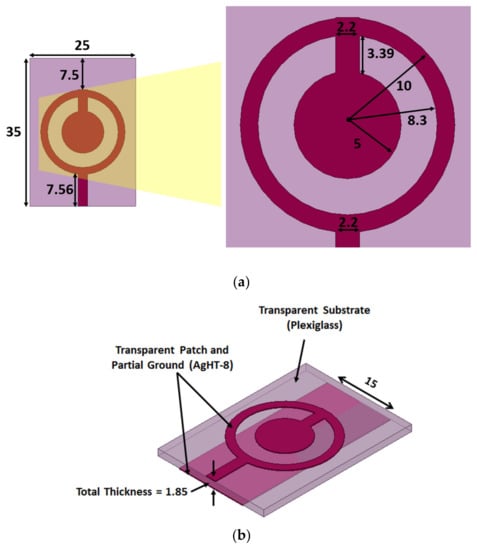
Figure 1.
Single-element transparent antenna geometry. (a) Dimensions of the top view of antenna. (b) Perspective view of antenna. (All dimensions in mm).
The step-by-step evolution of the antenna is shown in Figure 2. Step 1 to step 3 are configurations with the full ground plane. In step 1, a circular ring attached to the feedline is realized. It is observed that a dip is observed between 3.6 and 5 GHz; however, the reflection coefficient level is not satisfactory, as it does not cross the −10 dB threshold. In the next step, a vertical stub on the top side inside the circular ring is introduced that leads to the generation of frequency band on the higher side after 5 GHz. As that band is not of interest, a solid circular section is added in step 3 after which the ground plane variation is carried out (Proposed) that leads to attainment of the required frequency band.
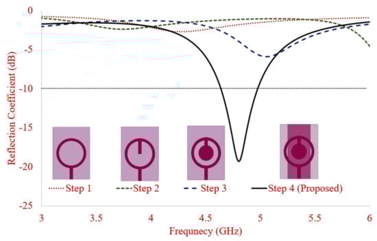
Figure 2.
Antenna evolution.
The single-element transparent antenna is optimized before finalizing the design. The reflection coefficient performance of the radiator is analyzed by varying antenna geometrical parameters, such as inner cylinder radius, outer cylinder radius, and ground plane width as shown in Figure 3a–c.
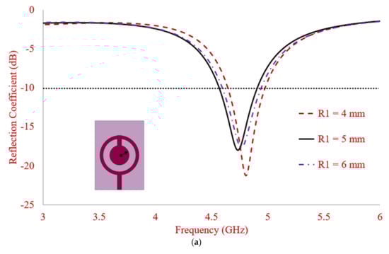
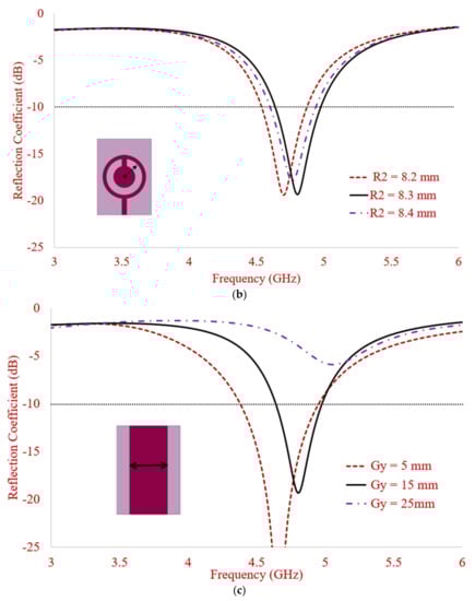
Figure 3.
Parametric analysis of various antenna parameters in terms of S11. (a) Effects of R1. (b) Effects of R2. (c) Effects of Gy.
The effect on S11 by varying the innermost circular radius is depicted in Figure 3a, where it can be observed that the application frequency can be optimized by varying the radius. As the radius increases, the frequency shifts more toward the lower side and vice versa. So the optimal radius to achieve the best performance is selected as 5 mm. Varying the outer radius also helps in optimizing the required frequency band along with the return loss as observed in Figure 3b. The optimum radius to achieve the best performance is selected as 8 mm. The ground plane variation is carried out to achieve the best possible impedance bandwidth and return loss, where it is observed in Figure 3c that for a ground plane width of 5mm, the reflection coefficient and bandwidth is the maximum; however, the targeted sub-6 GHz 5G band is 4.60–4.94 GHz, which is achieved at ground plane width of 15 mm.
The single element antenna is replicated along the Y-axis (case 1, Figure 4a) and X-axis (case 2, Figure 4b) to achieve the MIMO configuration. Case 1 has a separate ground profile with elements having similar orientation, whereas in case 2, the antennas are arranged oppositely with a connected ground profile. The inter-element distance of 5 mm and 15 mm, respectively, are kept between the elements to achieve spatial diversity as shown in Figure 4. It is observed that no additional techniques for isolation are used as a complex antenna geometry makes the fabrication process difficult for transparent antennas. To achieve the enhanced impedance matching and isolation, the layer beneath the substrate comprises partial ground, which is separated by a distance of 10 mm in case 1 and 0 mm in case 2. The dual element antenna dimension for case 1 and case 2 are 50 × 35 mm2 and 70 × 25 mm2, respectively.
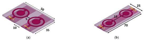
Figure 4.
Two-element transparent MIMO antenna geometry. (a) Case 1. (b) Case 2. (All dimensions are in mm).
3. Results and Discussion
This section may be divided by subheadings. It should provide a concise and precise description of the experimental results, their interpretation, as well as the experimental conclusions that can be drawn.
3.1. Single-Element Antenna
The optimized single element transparent antenna is fabricated using AgHT-8 (patch/ground) and Plexiglas (substrate) as shown in Figure 5. The conductive ground and patch layers are interfaced using adhesive tape on a transparent substrate. A conductive adhesive (silver/graphene paste) is used to connect the SMA connector.
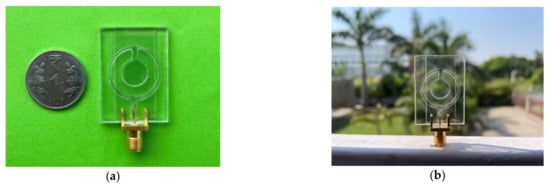
Figure 5.
Single-element transparent MIMO antenna fabricated prototype. (a) Top view. (b) Front view.
The reflection coefficient is well below -10 dB between the frequency span of 4.60–4.94 GHz (impedance bandwidth (IB) = 7.13%) with |S11| = 19.53 dB as illustrated in Figure 6 for single element structure that correlates well with the simulated structure results. The proposed antenna is useful in several countries, such as China, Japan, and Russia, for IoT devices working in the sub-6 GHz 5G band.
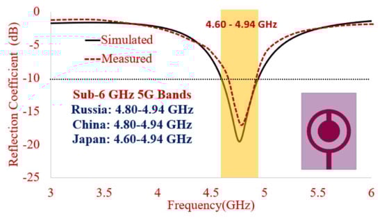
Figure 6.
Simulated and measured reflection coefficient.
The current distribution of antenna is depicted in Figure 7. The surface current on the outer circular section of solid cylindrical transparent material is symmetrically distributed in a λ resonant mode with the inner circular section being effective for the improved input impedance matching through the low impedance radial stub as deduced from Figure 3.
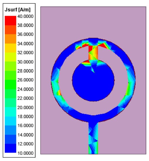
Figure 7.
Current distribution of single-element transparent antenna at 4.77 GHz.
3.2. 2-Element MIMO Antenna
The fabricated prototype of case 1 (separate ground profile) and case 2 (connected ground profile) is depicted in Figure 8, where the optical transparency of antennas is visible.
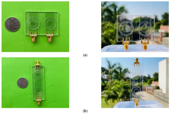
Figure 8.
Two-element transparent MIMO antenna fabricated prototype. (a) Case 1. (b) Case 2.
The dual element antenna performance in terms of reflection coefficient, radiation pattern, and current distribution along with other diversity parameters, such as ECC, DG, MEG, and CCL, are carried out in this section, where two different cases are considered to understand the effect of element position in the MIMO environment.
Figure 9 reveals the S parameters in terms of S11 and S12, where two MIMO antennas, using the elements aligned in horizontal and vertical direction, achieve an impedance bandwidth ranging from 4.65 to 4.97 GHz (6.65%) for case 1 and 4.67 to 4.94 GHz (5.61%) for case 2, respectively. The resonant peak within the impedance bandwidth for case 1 is observed at 4.81 GHz, having a value of |S11| = 17.18 and isolation |S12| greater than 17.10 dB, whereas for case 2, the resonant peak is observed at 4.81 GHz, having a value of |S11| = 14.86 and isolation |S12| greater than 17.38 dB, which shows that both designs show good MIMO isolation performance. The higher isolation in case 1 is due to a separate ground profile, while in case 2, it is due to the spatial diversity. The measured results agree well with the simulated results.
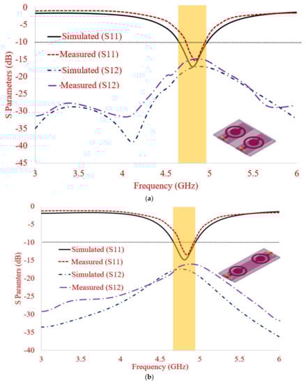
Figure 9.
Simulated and measured S parameters of 2-element transparent MIMO antenna. (a) Case 1. (b) Case 2.
The surface current distribution of a dual-element transparent antenna with a partial ground plane is depicted in Figure 10 for both cases. It is revealed that coupling between the two elements is negligible when port 1 is excited by keeping port 2 terminated at a 50 Ω matched load. The improved isolation is observed due to the use of a partial ground plane in case 1, while for case 2, the distance between the two elements results in lower mutual coupling.
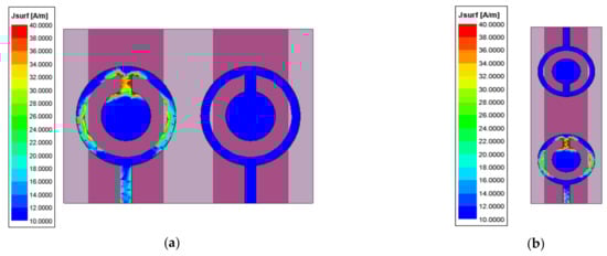
Figure 10.
Current distribution of 2-element transparent MIMO antenna at 4.81 GHz. (a) Case 1. (b) Case 2.
The co/cross-polarization 2D patterns for both the cases are illustrated in Figure 11 at E and H Plane, respectively, which is measured in the anechoic chamber as shown in Figure 12. Along E and H plane, the antenna shows a dipole and omnidirectional-formed radiation pattern for both the cases. The acceptable difference between the co/cross-pol pattern around 15 dB is observed, which guarantees good pattern diversity for the transparent MIMO antenna.
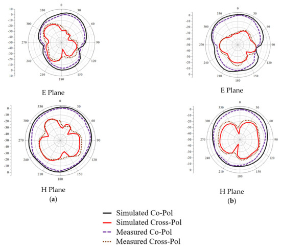
Figure 11.
Co/Cross Pol of 2-element transparent MIMO antenna at 4.81 GHz. (a) Case 1. (b) Case 2.
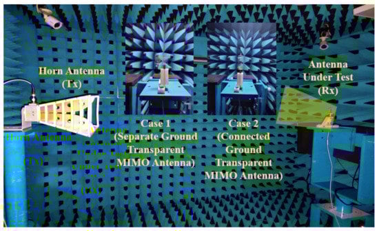
Figure 12.
Setup of radiation pattern measurement inside anechoic chamber.
3.3. MIMO Diversity Analysis
The MIMO diversity performance is analyzed in terms of ECC, MEG, TARC, DG, and CCL, where it is ensured that the proposed antenna meets the diversity requirements recommended in [29,30,31,32].
ECC, which is an important diversity parameter, conveys the field correlation amid antenna elements in a MIMO system, which is calculated from far-field parameters referring to Equation (1) [29].
The emitted radiation pattern influenced by simultaneous port excitation is understood using ECC. The simulated value of ECC for the proposed transparent MIMO antenna is <0.05 for case 1 and <0.03 for case 2, as illustrated in Figure 12, which is well under the limit of 0.1 as recommended in [29].
DG in multiple MIMO antenna concerning a single antenna structure is the improvement in (SNR) signal-to-noise ratio. The ideal value of DG should be 10, according to [8] which is calculated referring to (2).
The diversity gain is calculated by using Equation (2).
Figure 13 illustrates that the diversity gain value of the proposed transparent MIMO antenna system is between 9.88 and 10 dB for both cases, which meets the MIMO diversity criteria.
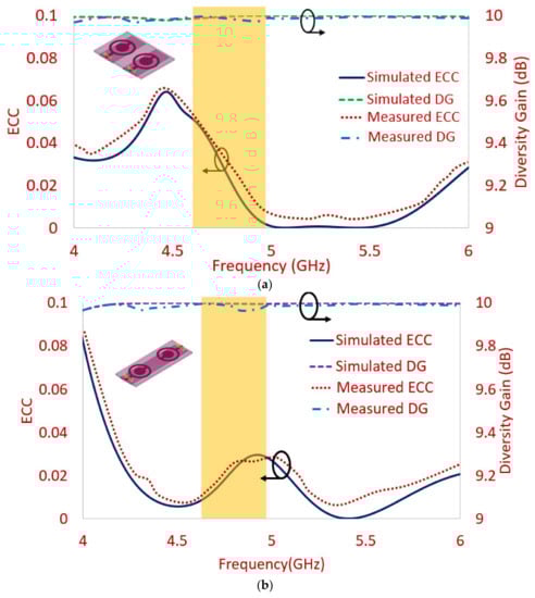
Figure 13.
Envelope correlation coefficient (ECC) and diversity gain (DG) of 2-element transparent MIMO antenna. (a) Case 1 (Separate Ground MIMO) (b) Case 2 (Connected Ground MIMO).
MEG of the MIMO system in a fading environment is the ratio of a diversity antenna and isotropic antenna received power levels that are calculated referring to Equation (3). The ratio of MEG1/MEG2 ranging between ±3 dB is good for the MIMO antenna system.
where, in Equation (3), and are the power gain and the existing power along the horizontal and vertical polarizations, respectively. The XPR is expressed as follows in Equation (4)
where, and represent the power received by vertically and horizontally polarized antennas, respectively.
The MEG plot of the antenna is shown in Figure 14, where it can be observed that MEG-1/MEG-2 are around one for both the cases, which signifies the improved diversity performance of the radiator.
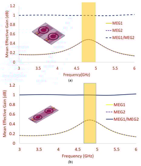
Figure 14.
Mean effective gain (MEG) of 2-element transparent MIMO antenna. (a) Case 1 (Separate Ground MIMO) (b) Case 2 (Connected Ground MIMO).
CCL signifies the maximum message rate limit over which the message is transmitted continuously through a channel without any losses. Figure 15 depicts the CCL of the transparent MIMO antenna, where it is observed that the value is below 0.5 bits/S/Hz for the proposed frequency band in both antennas, having horizontal and vertical alignment, which matches well with the ideal value. Channel capacity is calculated referring to (5).
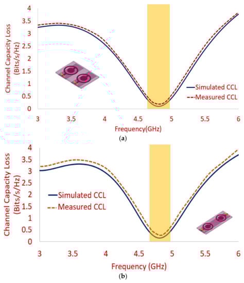
Figure 15.
Channel capacity loss (CCL) of 2-element transparent MIMO antenna. (a) Case 1 (Separate Ground MIMO) (b) Case 2 (Connected Ground MIMO).
The total active reflection coefficient (TARC) is one more parameter that also depicts the performance of the MIMO antenna in terms of isolation. It reflects the fraction of power levels of reflected and incident waves. The effective MIMO antenna operating bandwidth is derived using this parameter. The operating bandwidth is observed by varying the input phase with a step size of 30° starting from 0° to 180°. The proposed frequency band should be below-10 dB at phase angles covering the entire proposed bandwidth. The calculation of the total active reflection coefficient (TARC) is carried out using the equation given in (9).
where and are excitation and scattering vectors, respectively.
TARC is calculated between port 1 and port 2, where the necessary frequency bands are covered while achieving the stable characteristics as illustrated in Figure 16a,b. The TARC bandwidth ensures that high isolation is present among various ports present in the MIMO antenna.
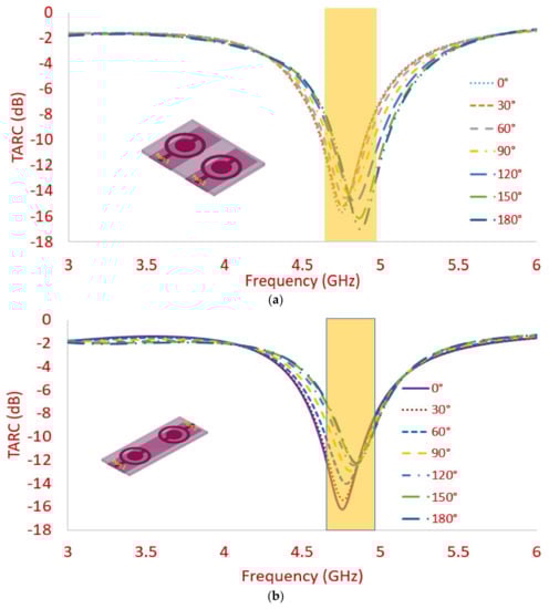
Figure 16.
Total active reflection coefficient (TARC) of 2-elements transparent MIMO antenna. (a) Case 1. (b) Case 2.
The simulated radiation efficiency along with gain values is depicted in Figure 17a,b, where efficiency value ranging from 48% to 53% and gain ranging from 1.02 to 1.83 dBi is observed for case 1, whereas for case 2, the simulated efficiency and gain value ranges between 58% and 59% and 1.56 and 1.65 dBi, respectively, which coincides with the measured values of gain very well. The low gain and efficiency in the case of transparent antennas is due to its low conductivity value that is inversely proportional to its optical transparency.
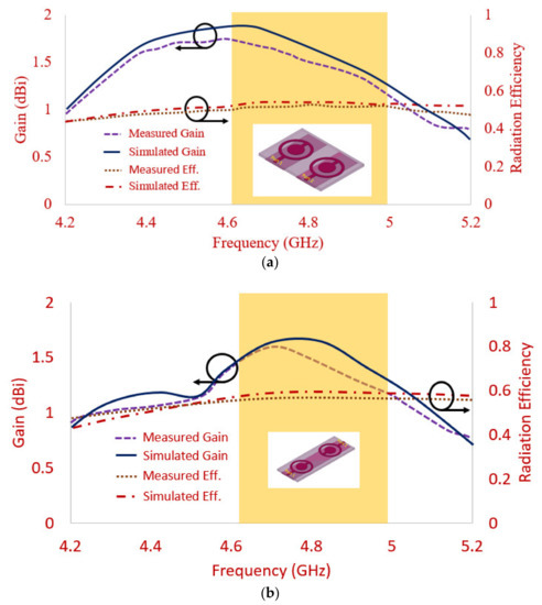
Figure 17.
Gain and efficiency of 2-element transparent MIMO antenna. (a) Case 1. (b) Case 2.
Table 1 illustrates the antenna performance for both cases in terms of the radiation efficiency, gain, and MIMO diversity parameters. It can be observed that for both cases, the results are almost similar; however, the case 2 antenna is more preferable, considering the connected ground structure [28].

Table 1.
Two-element transparent antenna characteristics.
Table 2 shows that very few transparent antennas are proposed for MIMO applications [24,25,26]. The antenna in [24] covers the sub-6 GHz band; however, no MIMO diversity parameters are analyzed. The MIMO antenna in [25] covers dual-band (2.23–2.46 GHz and 3.22–4.04 GHz) with high gain; however, the MIMO antenna is not fabricated, and the resonating bands do not cover the sub-6 GHz bands covered by the proposed antenna. Additionally, the size of the antenna structure is very big. A compact antenna with a size of 40×40 mm2 is proposed in [26]; however, the antenna radiates at the WLAN frequency band. Thus, it is observed that the proposed antenna outperforms another 2-port MIMO antenna in terms of the covered application band (sub-6 GHz band) and analysis of all MIMO diversity parameters (ECC, MEG, TARC, DG, and CCL), with the acceptable value of gain and efficiency.
Table 2.
Comparison of proposed 2-port transparent MIMO antenna with other 2-port MIMO antennas from literature.
Some salient features of the proposed transparent MIMO antenna are listed below:
- Where extreme space limitations on a compact circuit board need to be mitigated, transparent antennas offer easy integration while saving space. It can be placed anywhere, thus offering a degree of integration flexibility unrivaled by other antenna solutions.
- Transparent structure, sub-6 GHz band (4.60–4.94 GHz), more than 15 dB isolation levels, shared ground and unshared ground configurations, the antenna meeting all MIMO diversity characteristics, acceptable gain, and radiation efficiency point out that the proposed MIMO antenna appears to be a commercially feasible solution for IoT devices.
- The proposed optically transparent MIMO antenna finds its applications in smart indoor devices, such as wireless repeaters and routers that work at the sub-6 GHz 5G band. It can be easily interfaced on the office and home buildings, where glass structures are utilized. That way, it maintains the aesthetics, owing to its transparency. In addition, such types of transparent antennas can be utilized in satellites with a small-form factor and also in cube satellites by repeating the structure to form an array structure, thus helping to meet the critical space necessities [33,34]. Transparent antennas over solar panels help in revenue generation by leasing out the panels to telecom operators [33,34,35].
4. Conclusions
Two different transparent dual-element MIMO antennas are proposed, for which the study on S parameters and MIMO diversity parameters is carried out. The antennas differ in the way that the elements are positioned along with the ground plane configuration. The antenna design with vertically positioned elements (Case 2) with connected ground shows an almost similar performance when compared to the horizontally positioned MIMO antenna (case 1), which has a separate ground structure. The −10 dB impedance bandwidth (IB), ranging from (5.61%) 4.67 to 4.94 GHz with isolation greater than 15 dB is achieved between inter-elements in case 2. Additionally, the value of the envelope correlation is under 0.05, and DG is nearly 10 dB. The antenna shows the the ratio of MEG is around 1 and the CCL values are below 0.5 bits/s/Hz. The radiation efficiency and gain of more than 45% and 1 dBi, mitigation of visual clutter, no co-site location issues, and complete transparency make the proposed transparent connected ground dual-element MIMO antenna suitable for smart devices using sub-6 GHz 5G in IoT applications.
Author Contributions
Conceptualization, A.D., M.P. and I.E.; methodology, M.P., I.A. and C.Z.; software, A.D., I.E. and J.B.; validation, A.D., M.P. and I.E.; formal analysis, J.B. and C.Z.; investigation, J.R., A.D. and M.P.; resources, A.D. and I.E.; writing—original draft preparation, A.D., M.P. and I.E.; writing—review and editing, R.A.A.-A., J.R., M.P. and C.Z.; visualization, A.D., I.A. and I.E.; supervision, J.R. and R.A.A.-A.; project administration, J.B.; funding acquisition, J.R. All authors have read and agreed to the published version of the manuscript.
Funding
This work is supported by the Moore4Medical project, funded within ECSEL JU in collaboration with the EU H2020 Framework Programme (H2020/2014-2020) under grant agreement H2020-ECSEL-2019-IA-876190, and Fundação para a Ciência e Tecnologia (ECSEL/0006/2019).
Data Availability Statement
All data are included within manuscript.
Acknowledgments
This work is also funded by the FCT/MEC through national funds and when applicable co-financed by the ERDF, under the PT2020 Partnership Agreement under the UID/EEA/50008/2020 project.
Conflicts of Interest
The authors declare no conflict of interest.
References
- Andrews, J.G.; Buzzi, S.; Choi, W.; Hanly, S.V.; Lozano, A.; Soong, A.C.K.; Zhang, J.C. What Will 5G Be? IEEE J. Sel. Areas Commun. 2014, 32, 1065–1082. [Google Scholar] [CrossRef]
- Desai, A.; Upadhyaya, T.; Patel, R. Compact wideband transparent antenna for 5G communication systems. Microw. Opt. Technol. Lett. 2018, 61, 781–786. [Google Scholar] [CrossRef]
- Mias, C.C.T.; Prountzos, N.; Koutsogeorgis, D.C.; Liew, S.C.; Oswald, C.; Ranson, R.; Cranton, W.M.; Thomas, C.B. Optically transparent microstrip antennas. In Proceedings of the IEE Colloquium on Antennas for Automotives (Ref. No. 2000/002), London, UK, 10 March 2000; pp. 1–8. [Google Scholar]
- Desai, A.; Upadhyaya, T.; Palandoken, M.; Patel, R.; Patel, U. Dual band optically transparent antenna for wireless applications. In Proceedings of the 2017 IEEE Asia Pacific Microwave Conference (APMC), Kuala Lumpur, Malaysia, 13–16 November 2017; pp. 960–963. [Google Scholar]
- Hassan, A.; Ali, S.; Hassan, G.; Bae, J.; Lee, C.H. Inkjet-printed antenna on thin PET substrate for dual band Wi-Fi communications. Microsyst. Technol. 2016, 23, 3701–3709. [Google Scholar] [CrossRef]
- Desai, A.; Upadhyaya, T.; Patel, J.; Patel, R.; Palandoken, M. Flexible CPW fed transparent antenna for WLAN and sub-6 GHz 5G applications. Microw. Opt. Technol. Lett. 2020, 62, 2090–2103. [Google Scholar] [CrossRef]
- Srivastava, K.; Kumar, S.; Kanaujia, B.K.; Dwari, S. Design and packaging of ultra-wideband multiple-input-multiple-output/diversity antenna for wireless applications. Int. J. RF Microw. Comput. Aided Eng. 2020, 30, e22357. [Google Scholar] [CrossRef]
- Khalid, M.; Iffat Naqvi, S.I.; Hussain, N.; Rahman, M.; Fawad; Mirjavadi, S.S.; Khan, M.J.; Amin, Y. 4-Port MIMO Antenna with Defected Ground Structure for 5G Millimeter Wave Applications. Electronics 2020, 9, 71. [Google Scholar] [CrossRef] [Green Version]
- Adnan, G.; Li, X.J.; Awan, W.A.A.; Naqvi, S.I.I.; Hussain, N.; Seet, B.C.; Alibakhshikenari, M.; Falcone, F.; Limiti, E. Design and Realization of a Frequency Reconfigurable Multimode Antenna for ISM, 5G-Sub-6-GHz, and S-Band Applications. Appl. Sci. 2021, 11, 1635. [Google Scholar]
- Akhtar, F.; Naqvi, S.I.; Arshad, F.; Amin, Y.; Tenhunen, H. A flexible and compact semicircular antenna for multi-ple wireless communication applications. Radioengineering 2018, 27, 671–678. [Google Scholar] [CrossRef]
- Sharawi, M.S.; Numan, A.B.; Aloi, D.N. Isolation Improvement in a Dual-Band Dual-Element Mimo Antenna System Using Capacitively Loaded Loops. Prog. Electromagn. Res. 2013, 134, 247–266. [Google Scholar] [CrossRef] [Green Version]
- Dkiouak, A.; Zakriti, A.; El Ouahabi, M. Design of a compact dual-band MIMO antenna with high isolation for WLAN and X-band satellite by using orthogonal polarization. J. Electromagn. Waves Appl. 2019, 34, 1254–1267. [Google Scholar] [CrossRef]
- You, X.; Gao, H.; Zhou, L.; Zhao, H. Compact dual-element inverted-F MIMO antenna system with enhanced isolation. Microw. Opt. Technol. Lett. 2015, 58, 363–368. [Google Scholar] [CrossRef]
- Shoaib, S.; Shoaib, I.; Shoaib, N.; Chen, X.; Parini, C.G. Design and Performance Study of a Dual-Element Multiband Printed Monopole Antenna Array for MIMO Terminals. IEEE Antennas Wirel. Propag. Lett. 2014, 13, 329–332. [Google Scholar] [CrossRef]
- Yang, Y.; Chu, Q.; Mao, C. Multiband MIMO antenna for GSM, DCS, and LTE indoor applications. IEEE Antennas Wirel. Propag. Lett. 2016, 15, 1573–1576. [Google Scholar] [CrossRef]
- Moradikordalivand, A.; Leow, C.Y.; Rahman, T.A.; Ebrahimi, S.; Chua, T.H. Wideband MIMO antenna system with dual polarization for WiFi and LTE applications. Int. J. Microw. Wirel. Technol. 2015, 8, 643–650. [Google Scholar] [CrossRef]
- Wang, X.; Du, Z.; Gong, K. A compact dual-element antenna array for adaptive MIMO system. Microw. Opt. Technol. Lett. 2008, 51, 348–351. [Google Scholar] [CrossRef]
- Kumari, T.; Das, G.; Sharma, A.; Gangwar, R.K. Design approach for dual element hybrid MIMO antenna arrangement for wideband applications. Int. J. RF Microw. Comput. Eng. 2018, 29, e21486. [Google Scholar] [CrossRef]
- Sharma, M. Design and Analysis of MIMO Antenna with High Isolation and Dual Notched Band Characteristics for Wireless Applications. Wirel. Pers. Commun. 2020, 112, 1587–1599. [Google Scholar] [CrossRef]
- Saurabh, A.K.; Meshram, M.K. Compact sub-6 GHz 5G-multiple-input-multiple-output antenna sys-tem with enhanced isolation. Int. J. RF Microw. Comput.-Aided Eng. 2020, 30, e22246. [Google Scholar] [CrossRef]
- Khan, M.I.; Khattak, M.I.; Rahman, S.U.; Qazi, A.B.; Telba, A.A.; Sebak, A. Design and Investigation of Modern UWB-MIMO Antenna with Optimized Isolation. Micromachines 2020, 11, 432. [Google Scholar] [CrossRef] [Green Version]
- Li, H.; Zhang, G.; Xu, J.; Ding, J.; Guo, C. Aperture-coupling fed high isolation polarization diversity dual-element MIMO antenna system for WLAN application. Microw. Opt. Technol. Lett. 2017, 59, 1178–1182. [Google Scholar] [CrossRef]
- Chattha, H.T. 4-Port 2-Element MIMO Antenna for 5G Portable Applications. IEEE Access 2019, 7, 96516–96520. [Google Scholar] [CrossRef]
- So, K.K.; Chen, B.J.; Chan, C.H.; Luk, K.M. Study of MIMO Antenna Made of Transparent Conduc-tive ITO Films. In Proceedings of the IEEE Asia-Pacific Microwave Conference (APMC), Singapore, 10−13 December 2019; pp. 515–517. [Google Scholar]
- Desai, A.; Upadhyaya, T.; Palandoken, M.; Gocen, C. Dual band transparent antenna for wireless MIMO system applications. Microw. Opt. Technol. Lett. 2019, 61, 1845–1856. [Google Scholar] [CrossRef]
- Li, Q.L.; Cheung, S.W.; Wu, D.; Yuk, T.I. Optically Transparent Dual-Band MIMO Antenna Using Micro-Metal Mesh Conductive Film for WLAN System. IEEE Antennas Wirel. Propag. Lett. 2016, 16, 920–923. [Google Scholar] [CrossRef]
- Sharawi, M.S. Printed Multi-Band MIMO Antenna Systems and Their Performance Metrics [Wireless Corner]. IEEE Antennas Propag. Mag. 2013, 55, 218–232. [Google Scholar] [CrossRef]
- Sharawi, M.S. Current misuses and future prospects for printed multiple-input, multiple-output antenna systems. IEEE Antennas Propag. Mag. 2017, 59, 162–170. [Google Scholar] [CrossRef]
- Desai, A.; Palandoken, M.; Kulkarni, J.; Byun, G.; Nguyen, T.K. Wideband Flexi-ble/Transparent Connected-Ground MIMO Antennas for Sub-6 GHz 5G and WLAN Applications. IEEE Access 2021, 9, 147003–147015. [Google Scholar] [CrossRef]
- Desai, A.; Bui, C.D.; Patel, J.; Upadhyaya, T.; Byun, G.; Nguyen, T.K. Compact Wide-band Four Element Optically Transparent MIMO Antenna for mm-Wave 5G Applications. IEEE Access 2020, 8, 194206–194217. [Google Scholar] [CrossRef]
- Elfergani, I.T.E.; Hussaini, A.S.; Rodriguez, J.; Abd-Alhameed, R. Antenna Fundamentals for Legacy Mobile Applications and Beyond; Springer: Cham, Switzerland, 2017; pp. 1–659. [Google Scholar]
- Elfergani, I.; Iqbal, A.; Zebiri, C.; Basir, A.; Rodriguez, J.; Sajedin, M.; Pereira, A.D.O.; Mshwat, W.; Abd-Alhameed, R.; Ullah, S. Low-Profile and Closely Spaced Four-Element MIMO Antenna for Wireless Body Area Networks. Electronics 2020, 9, 258. [Google Scholar] [CrossRef] [Green Version]
- White, C.; Khaleel, H.R. Flexible Optically Transparent Antennas. WIT Trans. State Art Sci. Eng. 2014, 82, 59–70. [Google Scholar] [CrossRef]
- Liu, X.; Jackson, D.R.; Chen, J.; Liu, J.; Fink, P.W.; Lin, G.Y.; Neveu, N. Transparent and nontransparent microstrip an-tennas on a CubeSat: Novel low-profile antennas for CubeSats improve mission reliability. IEEE Antennas Propag. Mag. 2017, 59, 59–68. [Google Scholar] [CrossRef]
- Roo-Ons, M.; Shynu, S.; Ammann, M.; McCormack, S.; Norton, B. Transparent patch antenna on a-Si thin-film glass solar module. Electron. Lett. 2011, 47, 85–86. [Google Scholar] [CrossRef] [Green Version]
Publisher’s Note: MDPI stays neutral with regard to jurisdictional claims in published maps and institutional affiliations. |
© 2022 by the authors. Licensee MDPI, Basel, Switzerland. This article is an open access article distributed under the terms and conditions of the Creative Commons Attribution (CC BY) license (https://creativecommons.org/licenses/by/4.0/).