Highlights
What are the main findings?
- Bond strength of veneering composite to CAD/CAM FRC (Trinia) was evaluated regarding fiber orientation, load direction, and aging.
- Fiber orientation and load direction showed no significant effect; aging significantly reduced SBS, and fractographic analysis confirmed the adhesive interface as the limiting factor.
What are the implications of the main findings?
- Proper adhesive protocols can ensure durable bonding despite hydrolytic degradation.
- Veneered FRC restorations can be considered a reliable clinical option.
Abstract
Fiber-reinforced composites (FRCs) are increasingly utilized in computer-aided design/computer-aided Manufacturing (CAD/CAM) workflows for both definitive and provisional restorations. Veneering these materials is essential not only for achieving aesthetic outcomes, but also to prevent direct exposure of oral tissues to glass fibers. This study evaluated the short- and long-term shear bond strength (SBS) between a veneering composite and FRC (Trinia, Bicon) with varying bonding interface orientations and load directions. Specimens were sectioned into discs with 1.5° or 45° tilt with respect to material’s layering planes and veneered with a composite pin (Ceramage, Shofu Inc.). SBS was tested after 24 h and 180 days of water storage, with forces applied either parallel or perpendicular to the layer orientation seen at the bonding interface. Long-term water storage significantly reduced SBS (24 h: 23.9 MPa vs. 180 d: 18.1 MPa, p < 0.001). In contrast, neither cutting direction (1.5° vs. 45°, p = 0.584) nor loading direction (parallel vs. perpendicular, p = 0.367) significantly influenced SBS. These results suggest veneering of the tested FRC material is clinically viable regardless of interface orientation or load direction. Although aging significantly reduced SBS, this was not clinically relevant, indicating that appropriate adhesive protocols may ensure durable bonding.
1. Introduction
Long-term provisional crowns play an important role in dental treatment, especially in cases where extended monitoring of the patient’s condition is necessary before final restorations can be placed. Traditionally, these long-term provisional restorations were fabricated from non-precious metals, which, while durable, offered poor aesthetics. With the advent of composite resins, there was a shift towards materials that provided a better visual outcome [1,2]. However, these resins, while aesthetically pleasing, are prone to fractures, wear, and discoloration over time, limiting their suitability for extended use [3]. Given the increasing demand for long-lasting, aesthetically satisfying provisional and permanent restorations, the limitations of conventional composite resins have prompted the exploration of alternative materials [4].
FRCs have a long history of use in dentistry across a wide range of applications. They are well-established as glass fiber posts [5], which have proven their reliability and are widely adopted in clinical practice, as well as in fiber-reinforced retainers [6], fiber-reinforced resins in restorative treatments [7], and glass fiber strips for splinting or reinforcement. Building on these established applications, the incorporation of glass fibers into CAD/CAM materials represents a natural progression, allowing these advanced materials to combine the mechanical benefits of fiber reinforcement with the precision and efficiency of computer-aided workflows. More recently, these FRC’s have become available in CAD/CAM form. [8]. Materials such as Trinia (Trinia, Bicon, Arborway, Boston, MA, USA) (Figure 1), which was used in this research, provide high flexural strength, durability, and esthetics, supporting both definitive and long-term provisional restoration [9,10].
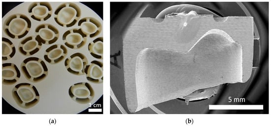
Figure 1.
(a) FRC disc (Trinia, Bicon) with CAD/CAM processed frameworks. (b) Scanning electron microscopy (SEM)-Image of a Sample with a milled FRC Framework (Trinia, Bicon).
FRC, has various indications, including frameworks for fixed dental prostheses (FDPs) on teeth and implants, as well as removable prostheses [11,12,13]. Comprising a composite matrix and embedded glass fiber mats, Trinia (Trinia, Bicon) offers significant advantages such as high strength, toughness, and low density [14]. These properties are critical for the long-term success of FDPs. However, exposed fibers present a polishing challenge, necessitating veneering with composite resin to achieve satisfactory aesthetics and function. As with other materials, veneering poses a risk of chipping, especially given the material’s flexibility [9]. Trinia (Trinia, Bicon), used in this examination, consists of a composite matrix reinforced with interwoven glass fiber mats, which are processed into discs suitable for CAD/CAM fabrication. This enables the production of restoration frameworks entirely within a digital workflow [15]. Due to the layered structure of the material, CAD/CAM processing inevitably results in surfaces with varying fiber content, depending on the orientation and depth of the cut (Figure 2a–c). As a result, the bonding surface of a restoration may exhibit significant differences in fiber exposure [16,17].
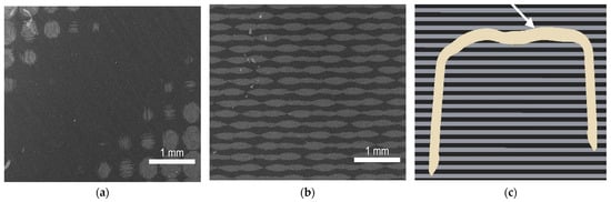
Figure 2.
(a,b) SEM-images of polished bonding surfaces of FRC specimens consisting of alternating layers of woven glass fiber sheets (light gray) and epoxy resin (dark gray) at 30× magnification: (a) 1.5° cutting direction: Alternating epoxy and glass fiber stripes are several millimeters broad. Fiberless epoxy resin areas can be seen in the middle. (b) 45° cutting direction: Finely striped pattern at the bonding interface for which about 10 fibers and epoxy layers will lie beneath the bonded composite pin (d = 2.38 mm) of a SBS test. (c) Cross-sectional view of an STL-file of a ready-to-mill crown FRC Framework. Gray striped background for schematic representation of the FRC blank with alternating glass fiber and composite layers. The framework structure intersects the layers at different angles. Occlusal areas, for example, meet the layers at very small angles (see arrow).
Given this variability in bonding interface surfaces along a FRC frame, it is crucial to understand whether the cutting and loading direction influences the bond strength between the FRC and veneering composite.
Previous research on FRCs has primarily focused on their mechanical performance and durability under different aging conditions. Several studies demonstrated that water storage led to hydrolytic degradation and a reduction of bond strength between FRCs and veneering composites. For example, Bunz et al. investigated SBS of veneering composites to high-performance polymers, including fiber-reinforced systems, and found significant deterioration after long-term water storage [18]. Similarly, Rosentritt et al. reported that prolonged storage in water weakens resin-based CAD/CAM materials due to hydrolytic effects [19]. Keski-Nikkola et al. also confirmed reduced bonding durability of veneering composites to FRC substrates under aging conditions [20].
Other studies investigated the role of surface conditioning protocols, showing that methods such as air-particle abrasion and different adhesive systems can significantly improve adhesion at the composite–FRC interface [21,22]. Furthermore, investigations into the influence of fiber orientation have mainly addressed flexural properties rather than adhesive performance. Yasue et al. showed that fiber alignment significantly influences flexural strength in CAD/CAM FRC blocks [8]. However, bonding behavior seems to be less sensitive to fiber orientation, as also supported by earlier analyses of resin–composite interfaces [23].
Despite these valuable insights, there is still limited knowledge regarding how the orientation of the bonding interface created during CAD/CAM processing and the direction of loading during function affect the SBS to veneering composites. In addition, while the effects of water storage on adhesive interfaces are well recognized, studies combining these factors in one experimental design are scarce. Therefore, the present work aims to close this gap by systematically evaluating the impact of cutting direction, load direction, and long-term water storage on the bond strength between veneering composite and a CAD/CAM FRC material.
To address these factors, SBS tests, which are considered to be a reliable predictor of bond strength in the literature, were conducted [24] and three null hypotheses were formulated:
- Load direction does not influence the SBS between FRC and veneering composite.
- Cutting direction does not influence the SBS between FRC and veneering composite.
- Prolonged water storage does not influence the SBS between FRC and veneering composite.
2. Materials and Methods
The internal structure of the used FRC material (Trinia, Bicon) consists of alternating layers of composite resin and interwoven glass fiber bundles. According to the manufacturer, the material comprises approximately 50–60% glass fibers and 40–50% modified epoxy resin by weight. Based on SEM of cross-sections prepared at 90° (Figure 3), the thickness of a single layer (glass fiber + epoxy resin) was determined to be approximately 160 µm. With a given cutting direction (angle α measured from the horizontal plane), the stripes (glass fiber + epoxy) at the bonding interface will have a width of 160 µm/sin(α) which amounts to 0.23 mm for α = 45° and around 6.11 mm for α = 1.5°. Consequently, when relating these stripe widths to the diameter d = 2.38 mm of a cylindric composite pin used in SBS tests according to ISO 29022 [25], the bonding surface beneath the pin will be predominantly exposed to either glass fiber bundles or epoxy resin for α = 1.5° whereas more than 10 layers will lie beneath the pin for α ≥ 45°. If bond strengths with regard to glass fibers and epoxy resin differed, this could affect overall bond strength to FRC materials.
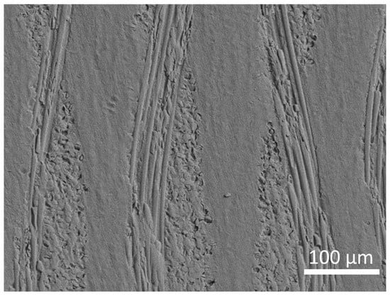
Figure 3.
SEM image of a polished FRC specimen (cutting direction: 90°) 250× magnification: Interwoven layers of glass fiber mats embedded in composite matrix. Two layers, consisting of composite and fibers are approximately 160 µm wide. The section was oriented such in the FRC disc that the interwoven fibers had orientations perpendicular and parallel with respect to the surface.
2.1. Specimen Preparation
To investigate this effect, CAD/CAM FRC blanks (Trinia, Bicon) were sectioned into rectangular blocks using a precision cutting machine (Isomet High Speed Pro, Buehler, Lake Bluff, IL, USA) under water cooling. These blocks were then cut into 2 mm-thick discs at two angles: α = 1.5° (n = 104) and α = 45° (n = 102) relative to the horizontal plane. The final sample dimensions were 10 mm × 10 mm × 2 mm. Each specimen was embedded in acrylic resin (Technovit 4071, Heraus Kulzer, Hanau, Germany) for handling and grinding (Figure 4b). The specimens were grounded using a semi-automatic grinding and polishing machine (Tegramin-25, Struers, Willich, Germany) with silicon carbide abrasive papers (grit sizes: #220, #600, #1200) under water cooling to achieve standardized surfaces. Grinding was repeated if necessary.
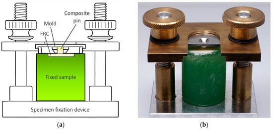
Figure 4.
Specimen fixation device with mold for composite pin application (a) schematic (b) with fixed sample.
2.2. Surface Treatment and Veneering
The embedded Trinia (Trinia, Bicon) discs were conditioned per the manufacturer’s recommendations. Specimens were sandblasted with 50 µm alumina particles at 0.1 MPa for 10 s (P-G400; Harnisch-Rieth, Winterbach, Germany) and steam-cleaned at 0.3 MPa for 10 s (Triton SLA, Bego, Bremen, Germany) before drying with oil-free compressed air for 10 s. An adhesive coating was applied to the FRC bonding interface with microbrushes in two steps. After application of a thin layer of the first adhesive component (CeraResin Bond I, Shofu Inc., Kyoto, Japan), another layer was added using the second component (CeraResin Bond II, Shofu Inc.). Each layer was massaged to the surface with microbrushes for 10 s. This bonding was light-cured for 180 s (Dentacolor XS, Heraeus Kulzer, Wehrheim, Germany). CeraResin Bond I contains ethanol as a solvent and silane to promote adhesion to glass ceramics or composite fillers. CeraResin Bond II consists of acetone, a functional monomer (4-AET), a polymerizable resin (UDMA), and a light-curing initiator system. Since FRC veneering was simulated, additional opaquer layers were added on top of the bonding, again in two steps. One first thin layer (Universal Opaque, Pre-Opaque, Shofu Inc.) was light-cured for 180 s, followed by two successive layers of the second opaque material (Universal Opaque, Opaque A30, Shofu Inc.), each light-cured for 180 s (Figure 5).
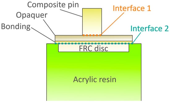
Figure 5.
Scheme of a composite pin bonded to a FRC specimen with designation of the different material layers and interfaces. Thickness of opaque layer and adhesive layer is not shown proportionally for better visualization.
The veneering composite (Ceramage, Shofu Inc.) was applied incrementally. Specimens were therefore secured in a clamping device according to ISO 29022 [25] (Figure 4a) with a stainless-steel disc having a central borehole (diameter: 2.38 mm) for composite resin application. The composite resin was placed incrementally with a 1 mm Composite Plugger (Aesculap Dental Instruments, B. Braun SE, Melsungen, Germany). The first layer was 0.2 mm thick, followed by 0.9 mm increments. Each increment was light-cured for 10 s (Smartlite Focus, Dentsply Sirona, DeTrey, Konstanz, Germany) at 1200 mW/cm2. After three increments, the pin reached ~2 mm height, followed by a final 20-s cure. For the 1.5° group, the position of each pin was selected such that the underlying bonding area exhibited an approximately equal distribution of fiber bundles and epoxy resin (~50% each).
Specimens were removed from the clamping device while exhibiting minimal stress on the composite pin. After manufacturing 15 composite pins, their bonding interface diameters were measured and recorded. Specimen images were captured using a light microscope for later position verification.
2.3. Storage Conditions
Specimens were stored in deionized water at 37 °C for either 24 ± 2 h or 180 ± 7 days.
2.4. Shear Bond Strength Testing
Prior to testing, any excess composite was removed from the specimens with a razor blade if necessary. SBS testing was performed according to ISO 29022 [25] using a universal testing machine (Z005; Zwick/Roell AG, Ulm, Germany) equipped with a 5 kN load cell. According to the calibration report, the relative measurement uncertainty of the load cell was less than 0.23% within the range of 10–200 N. The applied force was recorded using TestXpert III V1.4 (Zwick/Roell AG) software. The load cell (Type: KAF-TC, Zwick/Roell AG) was operated with a force drop threshold of 80% Fmax. For determination of the compressive yield strength, the displacement storage interval was set to 2 µm, while a coarser interval of 5 µm was applied up to fracture. The time storage interval was 0.1 s, and the force storage interval was 1 N. Specimens were clamped, aligned, and loaded at a crosshead speed of 1.0 ± 0.1 mm/min until failure (Figure 6). Forces were applied either parallel or perpendicular to the fiber layer orientation in half of the specimens within each subgroup.
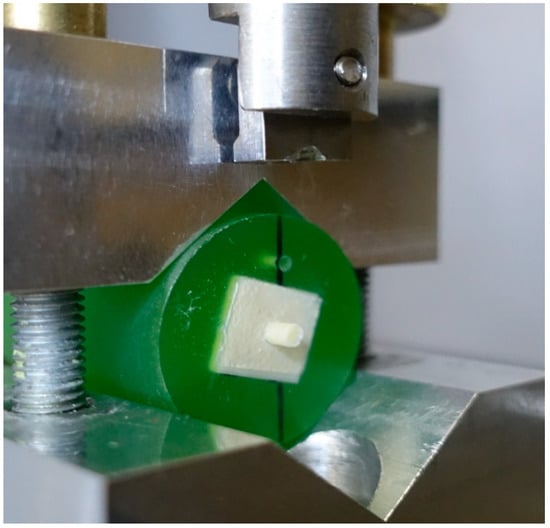
Figure 6.
SBS test setup according to ISO 29022 [25] with specimen. Since the stripe pattern was not visible after application of bonding and opaquer layers, its orientation was marked by a black line on the acrylic resin. In this image, the test force was applied parallel with respect to the stripes.
The maximum force (Fmax, N) was recorded, and SBS (σ, MPa) was calculated according to the following equation:
- σ = shear bond strength (MPa),
- Fmax = maximum force at failure (N),
- A = bonded area (mm2).
The bonded area of the composite cylinder (diameter 2.38 mm) was 4.45 mm2.
2.5. Fractographic Analysis
Fracture surface analysis was performed using optical microscopy (Smartzoom 5, Carl Zeiss AG, Oberkochen, Germany).
2.6. Statistical Analysis
Bond strength data were analyzed using IBM SPSS Statistics for Windows, Version 28.0 (IBM Corp., Armonk, NY, USA). Normality was confirmed using the Shapiro–Wilk test. Differences between storage conditions and loading orientations were analyzed using two-way ANOVA (α = 0.05).
3. Results
The SBS results are displayed in Figure 7 and detailed results for all test groups summarized in Table 1. The SBS was significantly affected by the duration of water storage. Specimens subjected to long-term water storage (180 days) showed a statistically significant reduction in SBS across all specimen types compared to those stored for a short period, 24 h (18.1 MPa vs. 23.9 MPa, p < 0.001). This indicates that prolonged exposure to water negatively affects the adhesive interface, potentially due to hydrolytic degradation of bonding components or water infiltration at the bonded interface.
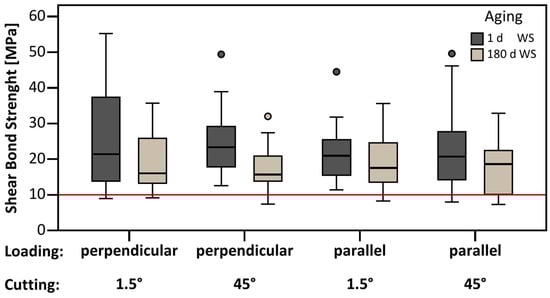
Figure 7.
SBS for samples with different cutting/loading directions tested after 1 day or 180 days of water storage (WS). The red line indicates the 10 MPa threshold often used to assess clinical eligibility.

Table 1.
SBS for different cutting-, loading- directions and aging.
In contrast to aging, cutting direction (orientation of the bonding interface) did not have a statistically significant impact on SBS. The mean SBS for specimens sectioned at 1.5° relative to the horizontal plane was 21.4 MPa, whereas specimens sectioned at 45° exhibited a mean SBS of 20.6 MPa (p > 0.584). This suggests that the angle of fiber reinforcement within the FRC material did not substantially alter the bonding performance under the tested conditions.
Similarly, the loading direction did not significantly affect the SBS values. Specimens loaded perpendicular to the fiber layers showed a mean SBS of 21.6 MPa, while those loaded parallel exhibited a mean SBS of 20.4 MPa (p > 0.367). These results suggest that the structural integrity of the FRC and its adhesive interface remains relatively stable regardless of the shear force direction (Table 1 and Table 2).
Table 2.
ANOVA results on SBS data for the factors aging, cutting direction, loading direction, and factor interactions.
Additionally, the interaction effects between cutting direction and aging (p > 0.702), cutting direction and loading direction (p > 0.493), aging and loading direction (p > 0.249), and the three-way interaction between cutting direction, aging, and loading direction (p > 0.573) were all found to be statistically insignificant.
Overall, while the bonding strength was notably reduced by extended water storage, neither the fiber orientation within the composite nor the direction of applied shear force significantly influenced the bond strength in the tested conditions.
Fractographic Observations and Failure Modes
To gain further insight into the failure mechanisms, a fractographic analysis was conducted. Digital images (Figure 8a–c) revealed four distinct failure modes: failure at the FRC/opaque interface (A1), failure at the opaque/composite interface (A2), mixed failure (A1 + A2), and adhesive/cohesive mixed failure (combined A1 + A2).
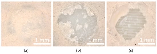
Figure 8.
Failure patterns: (a) Adhesive failure as a debonding at interface 2 (1.5° specimen) (b) Mixed failure as debonding at interface 1 and 2 (1.5° specimen) (c) Mixed failure as combination of cohesive + adhesive fracture in the composite pin + debonding at interface 1 (45° specimen).
In specimens sectioned at 1.5°, regions of composite matrix and fiber bundles alternated across the bonding surface due to the low cutting angle. To assess the local fiber content, specimens were imaged using optical microscopy before and after surface preparation. Pin positions were digitally tracked by overlaying pre- and post-processing images using image analysis software, allowing for precise localization of each pin relative to the underlying material structure. This method enabled classification of bonding areas according to their fiber content. Quantitative analysis of the pin distribution revealed an average fiber content of approximately 52% at the bonding interface for the 1.5° group. The fiber content for the 45° group was assumed to be 50%.
4. Discussion
Based on the experimental data, the following conclusions can be drawn regarding the null hypotheses:
- Loading direction did not significantly influence the SBS between FRC and veneering composite (p > 0.367).
- Cutting direction (fiber orientation) also showed no significant effect on SBS (p > 0.584).
- In contrast, prolonged water storage had a statistically significant negative impact on SBS (p < 0.001), thus leading to the rejection of the third null hypothesis only.
4.1. Influence of Water Storage
The duration of water storage exhibited the most pronounced effect on SBS (Figure 9), consistent with the findings of Bunz et al. [18], who demonstrated that long-term exposure to moisture significantly weakens the adhesive interface in high-performance polymer systems, including FRCs. In line with common SBS testing protocols, specimens are typically evaluated after short-term (1 day) and long-term (180 days) water storage [19,26,27]. In our study, SBS values decreased from 23.9 MPa at 1 day to 18.1 MPa after 180 days, highlighting the susceptibility of the adhesive bond to hydrolytic degradation over time. This degradation is likely due to water uptake by the polymer matrix, which causes plasticization, swelling, and eventual breakdown of interfacial adhesion. These observations are in line with previous reports, which showed that water storage over 6 months or longer can significantly reduce bond strength in various dental adhesive and composite systems [19,23,26,27,28], supporting the notion that prolonged exposure to an aqueous environment is a critical factor in the deterioration of adhesive interfaces. Similar environmental effects on interfacial bonding were reported in a study [29], where basalt-, glass-, and carbon-fiber reinforced polymer bars exposed to a seawater environment showed reduced interlaminar shear strength. However, the specimens were much larger and the materials differ from dental FRCs, limiting direct transfer of these results. Notably, long-term water storage, thermal cycling, and dynamic loading have been reported to exert similar weakening effects on the adhesive bond, although dynamic loading and thermal cycling can cause slightly greater reductions in bond strength [26,27]. Thermal cycling would have been applicable for the type of specimens used in our study, its omission represents a limitation. Dynamic loading, however, is very challenging to implement in classical SBS tests, which limits its inclusion in the present experimental setup. This trend was evident across all specimen configurations, suggesting that the moisture-induced degradation mechanism is primarily chemical and interfacial, rather than mechanical or structural. Comparable decreases in SBS across both sectioning angles (1.5° and 45°) and loading directions support the notion that water infiltration acts uniformly on the adhesive layer. Rosentritt et al. [19] observed similar reductions in bond strength and flexural modulus in water-stored CAD/CAM resin-based materials, reinforcing the importance of understanding material behavior under long-term exposure. Furthermore, the lack of significant difference between SBS reductions in parallel and perpendicular loading directions underlines the material’s isotropic degradation profile, aligning with findings from Yasue et al. [8] and Ewers et al. [9,14].
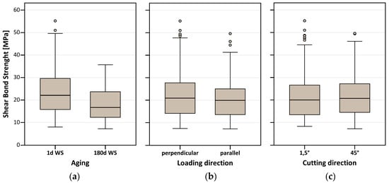
Figure 9.
Additional boxplots of SBS (MPa) illustrating the effects of (a) aging (1 d vs. 180 d water storage), (b) loading direction (perpendicular vs. parallel), and (c) cutting direction (1.5° vs. 45°).
4.2. Influence of Fiber Orientation and Loading Direction
Despite expectations that fiber orientation would influence stress distribution and interfacial failure modes, no statistically significant differences (Figure 9) were observed in SBS between specimens sectioned at 1.5° and 45° (21.4 MPa vs. 20.6 MPa, p > 0.584). This suggests that the internal fiber alignment, at least within the tested angular range, does not substantially affect bonding behavior. Similar outcomes were reported by Keski-Nikkola et al. [20], who found that the bond strength of veneering composite to FRC was relatively independent of fiber alignment when surface treatment and bonding protocols were standardized. Although only 1.5° and 45° sectioning angles were tested, no substantial differences would be expected at extreme orientations. At 0°, specimens mainly expose resin-rich regions, while 90° closely resembles 45° with only slightly altered fiber spacing. Thus, the selected angles are representative of the expected adhesive interface configurations. The absence of a significant effect of fiber orientation on SBS can be attributed to the bonding agent, which appears to interact equally well with both the glass fibers and the surrounding epoxy matrix. In our study, the measured maximum SBS values (~50–60 MPa) were substantially lower than the intrinsic flexural strength of the FRC substrate, which exceeds 100 MPa even in its weakest direction. Consequently, the adhesive interface represents the limiting factor rather than the fiber alignment itself. Fractographic analysis supports this interpretation: No fiber pull-out was observed, and failures were predominantly adhesive or mixed in nature. While fiber orientation is critical for the flexural performance of FRCs [8], it seems to have minimal influence on adhesive bonding under the conditions tested here. Likewise, the direction of applied load, whether parallel or perpendicular to the fiber layers, had no meaningful impact (Figure 9) on bond performance (20.4 MPa vs. 21.6 MPa, p > 0.367). This result supports the hypothesis that the multidirectional fiber arrangement in materials like Trinia (Trinia, Bicon) yields a mechanically homogenized substrate for adhesion, a conclusion also echoed by Vallittu and Özcan [4] and Ulusoy et al. [12]. From a micromechanical perspective, the lack of anisotropic behavior indicates that interfacial failure is not predominantly governed by fiber directionality under these specific bonding and loading conditions.
4.3. Surface Treatment and Adhesive Protocols
All specimens were subjected to a standardized surface treatment that included airborne-particle abrasion, the application of a material-specific primer, and veneering with composite resin. This approach aligns with best practices found in current literature [21,22], which emphasize chemical compatibility and micromechanical surface activation. The absence of significant differences in SBS due to fiber orientation or loading direction further indicates that a well-executed bonding protocol can compensate for intrinsic material variability and improve reliability. In clinical application, it is especially critical that dental laboratories meticulously follow the manufacturer’s surface treatment protocol. The use of compatible adhesive systems and standardized pre-treatment steps on the FRC surface ensures reliable bonding—even in complex prosthetic designs. Given that water storage still led to a significant reduction in bond strength, the development of more hydrolysis-resistant adhesive systems or additional sealing strategies before final restoration may be beneficial.
4.4. Micromechanical Retention and Glass Fiber Effects
Previous studies have proposed that exposed or cuted glass fibers may enhance micromechanical retention at the adhesive interface through a “bridging effect” [20,30,31,32,33]. In the present study, however, this effect could not be confirmed. This discrepancy may be due to the multidirectional fiber architecture of Trinia (Trinia, Bicon), which results in a more uniform distribution of fiber ends regardless of sectioning angle. Additionally, the applied surface treatment may not have sufficiently exposed or activated the fibers, or the adhesive resin may not have deeply penetrated the fiber network. It should also be noted that the bridging mechanism described in brittle matrix composites [30] may not directly apply to polymer-based systems like dental FRCs. In these materials, the properties of the polymer matrix itself and the adhesive chemistry likely play a more significant role in interfacial stability than the physical presence of fiber ends alone.
4.5. Clinical Implications
The findings of this study have direct implications for dental practice. The observed insensitivity of SBS to fiber orientation and loading direction simplifies clinical decision-making, as bonding performance appears consistent across various mechanical configurations. In daily practice, reliable adhesion is achievable when the laboratory team adheres strictly to the recommended surface treatment procedures and uses compatible adhesive systems. Nevertheless, because water storage still significantly reduced bond strength, future improvements may involve the development of more hydrolysis-resistant bonding agents or pre-sealing measures to protect the interface. While the role of exposed glass fibers in micromechanical retention could not be confirmed, future studies should investigate whether modified surface treatments, such as selective etching, silanization, or plasma activation, can better exploit fiber exposure. Long-term clinical studies and aging protocols with thermal and mechanical cycling are needed to better understand the durability of veneered FRC restorations in the oral environment.
5. Conclusions
Within the limitations of this in vitro study, the following conclusions can be drawn:
- Fiber orientation (1.5° vs. 45°) and loading direction (parallel vs. perpendicular) had no significant effect on shear bond strength (SBS), with mean values ranging from 20.4 to 21.6 MPa (p > 0.367–0.584).
- Water storage significantly reduced SBS (23.9 MPa at 1 day vs. 18.1 MPa at 180 days, p < 0.001), indicating hydrolytic degradation.
- Failure mode analysis revealed predominantly adhesive and mixed failures, confirming the adhesive interface as the limiting factor, although SBS values remained above clinically relevant thresholds.
Within these limits, Trinia-based restorations appear to offer reliable performance when bonded with standardized protocols.
Author Contributions
Conceptualization, F.S.S. and S.R. (Stefan Rues); Formal analysis, S.R. (Stefan Rues); Investigation, S.R. (Sven Räther); Methodology, A.T. and S.R. (Stefan Rues); Project administration, F.S.S.; Resources, A.T., P.R. and A.Z.; Supervision, F.S.S., P.R. and S.R. (Stefan Rues); Visualization, S.R. (Sven Räther); Writing—original draft, S.R. (Sven Räther); Writing—review and editing, A.T., Andreas Zenthöfer and S.R. (Stefan Rues). All authors have read and agreed to the published version of the manuscript.
Funding
This research received no external funding. For the publication fee we acknowledge financial support by Heidelberg University.
Data Availability Statement
The Data presented in this study are available on request from the corresponding author. The data are not publicly available due to institutional restrictions.
Acknowledgments
We are grateful to Mitsuji Teramae of the Research and Development Division of Shofu, Inc. (Kyoto, Japan) for providing the FRC disks and bonding and veneering materials.
Conflicts of Interest
This study was supported by Shofu, Inc. (Kyoto, Japan), who supplied FRC discs, primer, bonding, opaquer and veneering composites. There are no conflicts of interest.
Abbreviations
The following abbreviations are used in this manuscript:
| FRCs | Fiber-reinforced composites |
| CAD/CAM | Computer-aided design/Computer-aided manufacturing |
| SBS | Shear bond strength |
| SEM | Scanning electron microscopy |
| STL | Stereolithography |
| FDPs | Fixed dental prostheses |
| WS | Water storage |
References
- Alevizakos, V.; Mitov, G.; Teichert, F.; von See, C. The Color Stability and Wear Resistance of Provisional Implant Restorations: A Prospective Clinical Study. Clin. Exp. Dent. Res. 2020, 6, 568–575. [Google Scholar] [CrossRef]
- Tom, T.N.; Uthappa, M.; Sunny, K.; Begum, F.; Nautiyal, M.; Tamore, S. Provisional Restorations: An Overview of Materials Used. J. Adv. Clin. Res. Insights 2016, 3, 212–214. [Google Scholar] [CrossRef]
- Yannikakis, S.A.; Zissis, A.J.; Polyzois, G.L.; Caroni, C. Color Stability of Provisional Resin Restorative Materials. J. Prosthet. Dent. 1998, 80, 533–539. [Google Scholar] [CrossRef]
- Vallittu, P.; Özcan, M. Clinical Guide to Principles of Fiber-Reinforced Composites in Dentistry; Woodhead Publishing: Cambridge, UK, 2017. [Google Scholar]
- Alshabib, A.; Abid Althaqafi, K.; AlMoharib, H.S.; Mirah, M.; AlFawaz, Y.F.; Algamaiah, H. Dental Fiber-Post Systems: An in-Depth Review of Their Evolution, Current Practice and Future Directions. Bioengineering 2023, 10, 551. [Google Scholar] [CrossRef] [PubMed]
- Scribante, A.; Sfondrini, M.F.; Broggini, S.; D’Allocco, M.; Gandini, P. Efficacy of Esthetic Retainers: Clinical Comparison between Multistranded Wires and Direct-Bond Glass Fiber-Reinforced Composite Splints. Int. J. Dent. 2011, 2011, 548356. [Google Scholar] [PubMed]
- Albar, N.H.M.; Khayat, W.F. Evaluation of Fracture Strength of Fiber-Reinforced Direct Composite Resin Restorations: An in Vitro Study. Polymers 2022, 14, 4339. [Google Scholar] [CrossRef]
- Yasue, T.; Iwasaki, N.; Shiozawa, M.; Tsuchida, Y.; Suzuki, T.; Takahashi, H. Effect of Fiberglass Orientation on Flexural Properties of Fiberglass-Reinforced Composite Resin Block For CAD/CAM. Dent. Mater. J. 2019, 38, 738–742. [Google Scholar] [CrossRef] [PubMed]
- Ewers, R.; Perpetuini, P.; Morgan, V.J.; Marincola, M.; Wu, R.; Seemann, R. Trinia™—Metal-Free Restorations. Implants 2017, 1, 2–7. [Google Scholar]
- Varley, D.; Yousaf, S.; Youseffi, M.; Mozafari, M.; Khurshid, Z.; Sefat, F. Fiber-Reinforced Composites. In Advanced Dental Biomaterials; Elsevier: Amsterdam, The Netherlands, 2019; pp. 301–315. [Google Scholar]
- Tasaka, A.; Rues, S.; Schwindling, F.S.; Rammelsberg, P.; Yamashita, S. Retentive Force of Conical Crowns Combining Zirconia and Fiber-Reinforced Composite. J. Dent. 2022, 124, 104222. [Google Scholar] [CrossRef]
- Ulusoy, H.Ö.; Aydoğdu, H.M.; Tosun, İ. Bonding Performance of Cad/Cam Multilayer Glass-Fiber Reinforced High-Performance Polymer Cores with Different Veneer Materials. SSRN. 2024. Available online: https://ssrn.com/abstract=4848462 (accessed on 8 October 2025).
- Tasaka, A.; Schwindling, F.S.; Rues, S.; Rammelsberg, P.; Yamashita, S. Retentive Force of Telescopic Crowns Combining Fiber-Reinforced Composite and Zirconia. J. Prosthodont. Res. 2022, 66, 265–271. [Google Scholar] [CrossRef]
- Ewers, R.; Marincola, M.; Morgan, V.; Perpetuini, P.; Wagner, F.; Seemann, R. Restoration of the Atrophic Maxilla with Four Narrow and Ultrashort Implants. Int. J. Clin. Oral Maxillofac. Surg. 2018, 4, 35–41. [Google Scholar]
- Bonfante, E.A.; Suzuki, M.; Carvalho, R.M.; Hirata, R.; Lubelski, W.; Bonfante, G.; Pegoraro, T.A.; Coelho, P.G. Digitally Produced Fiber-Reinforced Composite Substructures For Three-Unit Implant-Supported Fixed Dental Prostheses. Int. J. Oral Maxillofac. Implant. 2015, 30, 321. [Google Scholar] [CrossRef]
- Shiozawa, M.; Tsuchida, Y.; Suzuki, T.; Takahashi, H. Discoloration of Fiber-Reinforced Composite Resin Disc For Computer-Aided Design/Computer-Aided Manufacturing After Immersion in Coffee and Curry Solutions. Dent. Mater. J. 2023, 42, 64–71. [Google Scholar] [CrossRef]
- Suzaki, N.; Yamaguchi, S.; Hirose, N.; Tanaka, R.; Takahashi, Y.; Imazato, S.; Hayashi, M. Evaluation of Physical Properties of Fiber-Reinforced Composite Resin. Dent. Mater. 2020, 36, 987–996. [Google Scholar] [CrossRef] [PubMed]
- Bunz, O.; Benz, C.I.; Arnold, W.H.; Piwowarczyk, A. Shear Bond Strength of Veneering Composite to High Performance Polymers. Dent. Mater. J. 2021, 40, 304–311. [Google Scholar] [CrossRef]
- Rosentritt, M.; Schneider-Feyrer, S.; Strasser, T.; Koenig, A.; Schmohl, L.; Schmid, A. thermoanalytical Investigations on the Influence of Storage Time in Water of Resin-Based Cad/Cam Materials. Biomedicines 2021, 9, 1779. [Google Scholar] [CrossRef]
- Keski-Nikkola, M.; Alander, P.; Lassila, L.; Vallittu, P. Bond Strength of Gradia® Veneering Composite to Fibre-Reinforced Composite. J. Oral Rehabil. 2004, 31, 1178–1183. [Google Scholar] [CrossRef] [PubMed]
- AlJehani, Y.A.; Baskaradoss, J.K.; Geevarghese, A.; AlShehry, M.A.; Vallittu, P.K. Shear Bond Strength between Fiber-Reinforced Composite and Veneering Resin Composites with Various Adhesive Resin Systems. J. Prosthodont. 2016, 25, 392–401. [Google Scholar] [CrossRef]
- Ando, E.; Kihara, T.; Shigeta, Y.; Sasaki, K.; Ikawa, T.; Hirai, S.; Shigemoto, S.; Ihara, K.; Kawamura, N.; Ogawa, T. Effect of Surface Treatment on Bond Strength of Fiber-Reinforced Cad/Cam Epoxy Resin. J. Jpn. Acad. Digit. Dent. 2021, 11, 95–101. [Google Scholar]
- Armstrong, S.R.; Keller, J.C.; Boyer, D.B. Mode of Failure in the Dentin-Adhesive Resin–Resin Composite Bonded Joint as Determined by Strength-Based (Μtbs) and Fracture-Based (Cnsb) Mechanical Testing. Dent. Mater. 2001, 17, 201–210. [Google Scholar] [CrossRef]
- Placido, E.; Meira, J.B.; Lima, R.G.; Muench, A.; de Souza, R.M.; Ballester, R.Y. Shear Versus Micro-Shear Bond Strength Test: A Finite Element Stress Analysis. Dent. Mater. 2007, 23, 1086–1092. [Google Scholar] [CrossRef] [PubMed]
- ISO 29022:2013; Dentistry—Adhesion—Notched-Edge Shear Bond Strength Test. European Committee for Standardization: Brüssel, Belgium, 2013.
- Blatz, M.B.; Sadan, A.; Martin, J.; Lang, B. in Vitro Evaluation of Shear Bond Strengths of Resin to Densely-Sintered High-Purity Zirconium-Oxide Ceramic after Long-Term Storage and thermal Cycling. J. Prosthet. Dent. 2004, 91, 356–362. [Google Scholar] [CrossRef] [PubMed]
- Bömicke, W.; Rammelsberg, P.; Krisam, J.; Rues, S. The Effects of Surface Conditioning and Aging on the Bond Strength between Composite Cement and Zirconia-Reinforced Lithium-Silicate Glass-Ceramics. J. Adhes. Dent. 2019, 21, 567. [Google Scholar] [PubMed]
- Heikkinen, T.; Matinlinna, J.; Vallittu, P.; Lassila, L. Long Term Water Storage Deteriorates Bonding of Composite Resin to Alumina and Zirconia Short Communication. Open Dent. J. 2013, 7, 123. [Google Scholar] [CrossRef]
- Wang, Z.; Zhao, X.-L.; Xian, G.; Wu, G.; Singh Raman, R.K.; Al-Saadi, S. Durability Study on interlaminar Shear Behaviour of Basalt-, Glass-and Carbon-Fibre Reinforced Polymer (B/G/Cfrp) Bars in Seawater Sea Sand Concrete Environment. Constr. Build. Mater. 2017, 156, 985–1004. [Google Scholar] [CrossRef]
- Leung, C.K.; Li, V.C. Effect of Fiber inclination on Crack Bridging Stress in Brittle Fiber Reinforced Brittle Matrix Composites. J. Mech. Phys. Solids 1992, 40, 1333–1362. [Google Scholar] [CrossRef]
- Fonseca, R.B.; Marques, A.S.; Bernades, K.d.O.; Carlo, H.L.; Naves, L.Z. Effect of Glass Fiber incorporation on Flexural Properties of Experimental Composites. BioMed Res. Int. 2014, 2014, 542678. [Google Scholar] [CrossRef]
- Müller, V.; Kabel, M.; Andrä, H.; Böhlke, T. Homogenization of Linear Elastic Properties of Short-Fiber Reinforced Composites–A Comparison of Mean Field and Voxel-Based Methods. Int. J. Solids Struct. 2015, 67, 56–70. [Google Scholar] [CrossRef]
- Nakamura, T.; Waki, T.; Kinuta, S.; Tanaka, H. Strength and Elastic Modulus of Fiber-Reinforced Composites Used For Fabricating Fpds. Int. J. Prosthodont. 2003, 16, 549. [Google Scholar]


Disclaimer/Publisher’s Note: The statements, opinions and data contained in all publications are solely those of the individual author(s) and contributor(s) and not of MDPI and/or the editor(s). MDPI and/or the editor(s) disclaim responsibility for any injury to people or property resulting from any ideas, methods, instructions or products referred to in the content. |
© 2025 by the authors. Licensee MDPI, Basel, Switzerland. This article is an open access article distributed under the terms and conditions of the Creative Commons Attribution (CC BY) license (https://creativecommons.org/licenses/by/4.0/).