Abstract
The precision of data gathered from Ultra-Weak Fiber Bragg Grating (UWFBG) sensing technology is limited when measuring strain within asphalt pavements. To better understand its measurement mechanism and correct possible errors, this study examines the synergy deformation behavior between UWFBG and asphalt mixtures under loads. Initially, the mesoscopic model of asphalt mixture containing UWFBG was constructed using a discrete element model, followed by the validation of the model. Then, the propagation of microcracks at the interface between the asphalt mixture and UWFBG was analyzed, revealing damage characteristics of this material under various loading stages. Additionally, a quantitative relationship between the crack width and the monitoring strain was identified. The significant effect of introducing the sensor on crack propagation and interface debonding in strain response was also highlighted. The results indicate that when displacement exceeds 1.4 mm during a bending test, the number of both damage and microcracks increases markedly, with cracks progressively developing. Especially at the UWFBG interface subjected to a tensile load, microcrack growth rises sharply, leading to the failure of the interface. The mor-UWFBG interface is not the main damage location, but it is the most vulnerable location to damage and may be the one affecting the monitoring of UWFBG. Without sensors, a consistent linear relationship between monitoring strain and crack width is observed within the asphalt mixture. After introducing the UWFBG sensor, the strain-crack response of the asphalt mixture is divided into three stages: crack initiation, crack propagation, and interface debonding. When the crack width surpasses 0.03 mm, interface debonding significantly influences the strain growth rate, indicating the necessity of correcting the synergy deformation.
1. Introduction
The monitoring of strain is essential for evaluating pavement damage [1,2]. To enable detailed monitoring of the internal structure of asphalt pavements, various sensors have been installed, greatly improving the accuracy of pavement condition assessments [3]. Because traditional Fiber Bragg Grating sensors have high reflectivity, the reflected signals from neighboring gratings can interfere with one another, typically limiting the number of multiplexed sensors on a single fiber to between tens and hundreds [4]. Ultra-weak Fiber Bragg Grating (UWFBG) offers a unique benefit for internal awareness of pavements due to the very low reflectivity. This feature significantly boosts distributed sensing capabilities, allowing for long-distance, multi-point monitoring and continuous coverage across the entire pavement [5,6,7,8]. Asphalt mixtures, which are nonlinear, heterogeneous, multiphase composite materials, exhibit notable uneven deformation and crack growth when subjected to loads and environmental changes [9,10,11,12]. If the bond between the sensor and the asphalt matrix does not deform synergistically, issues such as slippage, debonding, or even breakage are likely to occur, causing severe distortion or total failure of the monitoring signal [13]. Therefore, the accurate response of UWFBG within the complex material depends not only on their manufacturing quality but also critically on how effectively they deform in unison with the asphalt mixtures.
During the deformation process, stress concentration occurs on the sensor surface, which leads to the adhesive failure between the sensor and the asphalt mixture. Liu et al. [14] evaluated the feasibility of measuring the strain of asphalt pavement using flexibly packaged sensors, but did not analyze the interfacial interaction between the sensor and the asphalt mixture. At this stage, the sensor cannot fully deform in accordance with the deformation of the asphalt mixture [15]. Therefore, sensors are generally used to detect and locate fracture zones where large strains occur. Hu et al. [16] realized the localization of fracture zones in composite beam structures by using optical fiber sensor technology, and confirmed the potential of optical fiber sensors in pavement crack detection. So far, most studies have focused on the applicability of sensors in pavement crack detection [17,18], but few studies have specifically explored the meso-scale interfacial deformation and damage evolution mechanism between UWFBG sensors and asphalt mixtures, and the quantitative correlation between UWFBG monitoring strain and the actual crack width of asphalt mixtures remains unclarified, failing to provide a theoretical basis for correcting UWFBG measurement errors caused by interfacial debonding and inconsistent deformation.
Meanwhile, laboratory tests and the finite element method have been conducted to study the strain detection mechanism of the sensor [13,19]. However, limitations in laboratory methods and equipment make it challenging to investigate the interaction between UWFBG and asphalt mixtures at the mesoscopic scale. Achieving convergence is challenging when working with numerical problems that have significant discontinuities [20,21,22]. The discrete element method (DEM) offers a powerful tool for modeling elements with inherent stiffness and interface constitutive laws to simulate the interaction between various materials. Related studies have demonstrated that DEM can effectively represent the properties of asphalt mixtures [23,24,25,26]. Li et al. [27] developed a model of asphalt mixture specimens embedded with sensors using a 2D particle flow program, showing that factors such as sensor burial depth, quantity, and shape significantly affect the mechanical behavior and failure patterns of the overall structure. Liu et al. [28] created a mesoscopic model of asphalt mixtures with embedded strain sensors to investigate how the depth and arrangement of the sensors affect the stress distribution and the initiation and growth of cracks in beam specimens. Li et al. [29] developed a DEM-based Particle Flow Code model of asphalt mixtures incorporating embedded strain sensors. They found that the mortar phase mainly affects the overall mechanical behavior of both the sensors and the mixture, with stress concentration at the sensor flange being the primary reason for performance decline. Duan et al. [30] used a 3D particle flow program to create a model of asphalt mixture specimens with embedded strain sensors, finding a 2.7% decrease in the matrix’s structural strength due to the sensors. Zhang et al. [31] proposed a method to integrate fiber optic sensor models into a 3D discrete element model of asphalt concrete, incorporating practical definitions of the fiber’s mesoscopic contact model and mechanical properties, and introduced a validation approach for the discrete element model of asphalt concrete with embedded sensors. Collectively, these studies suggest that DEM is a valuable tool for understanding the interactions between sensors and asphalt mixtures. Nevertheless, existing DEM-based studies on sensor-embedded asphalt mixtures lack targeted analysis of the UWFBG-asphalt mortar interface damage characteristics under tensile loading, and have not established a quantitative correction model for the strain monitoring error induced by interfacial debonding during crack propagation, which restricts the practical application of UWFBG in high-precision pavement health monitoring.
The main goal of this research is to analyze the deformation behavior between UWFBG and asphalt mixtures. To achieve this objective, this study applies the DEM to investigate the coordinated deformation of UWFBG and asphalt mixture under loading conditions. Initially, through DEM, a microscopic model of asphalt mixtures embedded with UWFBG was constructed and validated, based on their structural features and material properties, to assess the deformation during a fracture. Then, the propagation of cracks and strain within UWFBG and asphalt mixtures was investigated during three-point bending tests. Finally, a correction model for measurement errors between UWFBG and asphalt mixtures was developed, offering a foundation for improving the accuracy in UWFBG-based monitoring of asphalt pavements.
2. Materials and Laboratory Testing
2.1. Raw Materials and Mix Design
In this study, a pre-strained optical cable with the model number SCJAGY-1B1-8.0-BL was used, featuring an outer sheath diameter of 8.0 ± 0.3 mm. The cable was manufactured by Yichang Raysensing Optoelectronics Technology Co., Ltd., Yichang, China. The structure of the cable is as follows: bare optical fiber (including core, cladding, and inner coating) is embedded in an acrylate buffer layer [32]. An outer tight buffer layer and sheath are fabricated to protect the internal fiber, mitigate strain, and offer overall protection. All component layers are firmly bonded together, providing the cable with excellent structural integrity. The performance parameters of the cable are presented in Table 1.

Table 1.
Fundamental characteristics of optical cables.
An AC-13 asphalt mixture was used in this research. The specimen dimensions are 300 mm × 50 mm × 50 mm, and the aggregate gradation is presented in Table 2. According to JTG E42-2005 [34], the apparent relative densities of aggregates within different particle size ranges were tested. The results are provided in Table 3. SBS (I-D) modified asphalt was tested according to JTG 3410-2025 [35]. The results are shown in Table 4. According to JTG F40-2004 [36], the optimal asphalt-aggregate ratio was determined to be 4.77%, with a designed void ratio of 4.1%.
Table 2.
Gradation of AC-13 asphalt mixture.
Table 3.
Density of various aggregates.
Table 4.
Basic properties of SBS modified asphalt.
2.2. Laboratory Testing
The specimens prepared in this experiment measured 300 mm × 50 mm × 50 mm. To accommodate the embedding of UWFBG sensors, the rutting plate molds (300 mm × 300 mm × 50 mm) with holes were specially manufactured first. Considering the structural limitations of the rutting test apparatus baffle plates, the vertical distance from the center of the pre-made holes in the molds to the top surface of the specimens was kept at 20 mm, and the holes all had an inner diameter of 10 mm. The preparation of the tested specimens is performed in accordance with the JTG 3410-2025 [35]. The manufactured mold was heated first at 175 °C. The preheated mold was then removed from the oven, and its inner walls were evenly coated with lubricant, followed by the placement of paper. Next, three-fifths of the total asphalt mixture weight was evenly placed into the mold up to a set height. UWFBG sensors were then embedded in the center of the mixture, with the grating positioned exactly 20 mm below the specimen’s top surface. After positioning the sensor, the remaining two-fifths of the asphalt mixture by weight was added evenly, filling the mold from the edges toward the center in a circular pattern. The middle portion of the mixture was kept slightly higher than the edges to allow space for compaction during rolling. The rolling wheel of the wheel roller was preheated to approximately 100 °C. The mold containing the mixture was placed on the roller’s platform. The rolling wheel was gently lowered, and the load was set to 9 kN. Rolling was performed in one direction for two round trips (four passes total). After unloading and lifting the wheel, the specimen rotated. The same load was applied again for continued rolling until the specimen achieved the Marshall standard compaction degree. This typically required around 12 round-trips (24 passes total), resulting in a specimen thickness of 50 mm. The mold with the compacted specimen was then cooled at room temperature for at least 12 h before demolding (Figure 1a). Finally, the specimen was cut to the dimensions of 300 mm × 50 mm × 50 mm using a cutting machine (Figure 1b).
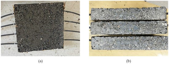
Figure 1.
Asphalt mixture specimens embedded with UWFBG: (a) Rutting plate specimen; (b) Cut beam specimen.
To validate the accuracy of the mesoscopic model through bending mechanics response, a three-point bending test was carried out on an asphalt mixture embedded with UWFBG using a Universal Material Testing Machine [35]. The loading rate was controlled at 0.5 mm/min. The grating was positioned at the center of the specimen, 20 mm away from the specimen’s bottom. During the bending tests, the strain of the UWFBG was monitored by a high-density UWFBG demodulator manufactured by Yichang Raysensing Optoelectronics Technology Co., Ltd., Yichang, China. The demodulator featured a sampling rate of 0.5 Hz, a spatial resolution of 0.2 m, and a strain accuracy of 1 µɛ. The three-point bending experiment is shown in Figure 2.
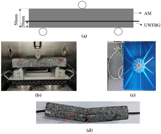
Figure 2.
Three-point bending test of asphalt mixture containing UWFBG: (a) Schematic diagram of the arrangement of UWFBG in the bending specimen; (b) Test process diagram; (c) Demodulator of UWFBG; (d) Failure diagram.
3. Discrete Element Model and Parameter Calibration
Based on relevant studies [37,38,39], both UWFBG and asphalt mortar can be created by uniform-sized discrete elementary particles. The asphalt mortar model was composed of 1.0 mm diameter spheres. The choice of this particle size is not arbitrary but is grounded in two main reasons: first, the 1.0 mm particle size corresponds to the minimum gradation range (0.075 to 2.36 mm) of the fine aggregate in the AC-13 asphalt mixture, allowing the meso-scale model to accurately capture the contact and deformation behavior between the UWFBG sensor and the asphalt mortar matrix at the actual material interface scale; second, this particle size strikes a balance between simulation accuracy and computational efficiency, avoiding the high computational costs associated with very fine particles while preserving critical information on interfacial deformation and microcrack propagation that could be lost with coarser particles. This size range is widely recognized as optimal for asphalt mixture DEM modeling in prior studies [23].
The UWFGB model consists of a sphere with a radius of 1.0 mm, which meets the minimum unit size required for properly combined asphalt mortar. The interfacial properties between the UWFBG and asphalt mortar are difficult to obtain through laboratory tests, and relevant measurement methods have rarely been reported in existing studies [31]. In this model, the interface was assumed to have the same properties as those between aggregates and asphalt mortar. Both the outer sheath of the UWFBG and mineral aggregates are regarded as rigid phases. This means that their own deformations under external loading are far smaller than those of asphalt mortar, and they exhibit similar mechanical behaviors in contact with asphalt mortar. This assumption is made based on the macroscopic physical similarity of materials and subsequent macroscopic validation. To a certain extent, it sacrifices the precise microscopic details in exchange for the feasibility of modeling and the effective capture of overall mechanical behavior. Although there may be minor deviations in the results of local debonding, this assumption successfully reveals that the UWFBG interface is the most vulnerable region in the asphalt mixture and provides a foundation for further research. Asphalt mixture part of the DEM model contains coarse aggregates (particle size larger than 2.36 mm), asphalt mortar, and air voids. The material composition was consistent with laboratory test specimens. To simplify the DEM model, air voids were assumed to distribute randomly within the asphalt mixture. Finally, a straight-line layout UWFBG model was placed into the asphalt mixture model without passing through any coarse aggregates.
The DEM model of the UWFBG sensor was developed based on the actual physical sensor. To improve simulation efficiency, the DEM model boundary for the sensor was designed with a square cross-section, called the walls in the model. The side length of the square cross-section is set to 8.0 mm, which is consistent with the outer diameter of the actual circular sensor sheath. This ensures that the equivalent contact area between the sensor and asphalt mortar is very close to the actual condition. The deviation of the contact area between the square (960 mm2) and the circle (753 mm2) is 27%. This size matching minimizes the distortion of interfacial stress distribution caused by the change in cross-sectional shape. The stress concentration pattern of the sensor in the asphalt mixture is essentially dominated by the significant stiffness mismatch between the sensor and the asphalt mortar matrix, rather than the geometric shape. Therefore, the simplification of the cross-sectional shape only causes local minor distortion of stress distribution in the horizontal non-loading direction. It exerts no significant influence on the overall stress concentration law of the sensor, nor on the tensile damage and debonding failure of the mortar-UWFBG interface, which is the core research object of this study. Inside the sensor model’s geometry, spheres with a radius of 1.0 mm were evenly packed. In accordance with the dimensions of the test specimen, a multi-faceted wall structure was constructed within the calculation domain, and the generated sensor DEM model was imported. The sensor was positioned at the central part of the wall structure, consistent with the configuration of laboratory tests. Based on the calculated volume ratios of aggregates for each gradation, a randomly distributed particle cluster was generated inside the specimen using the “ball distribute” command, as shown in Figure 3.
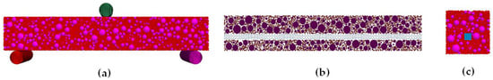
Figure 3.
Simulation model of three-point bending for asphalt mixture with UWFBG included: (a) DEM model for three-point bending where purple represents aggregate and red represents asphalt mortar; (b) Longitudinal section where magenta represents asphalt mixture and navy blue represents UWFBG; (c) Transverse section where purple represents aggregate, red represents asphalt mortar and cyan blue represents UWFBG.
Based on relevant studies [40,41,42], the mesoscale parameters for the contact model were established using the physical properties of the asphalt mixture components, as indicated by embedded strain sensors, and supported by relevant studies related to obtaining mesoscale parameters for UWFBG and basalt aggregates. The meso-structure parameters of each component are shown in Table 5. A three-point bending test was conducted in the laboratory to validate the DEM model without considering gravity. It is found that the simulation test results are close to the laboratory results, and the DEM model can be used for subsequent analysis.
Table 5.
Microscopic parameters of the linear parallel bond model within the asphalt mixture.
4. Results and Discussion
4.1. The Propagation Process of Microcrack Within Asphalt Mixture
In this study, the propagation process of microcrack is the core link to reveal the damage evolution and failure mechanism of the composite composed of asphalt mixture and UWFBG. Combining the correlation laws among damage degree, microcrack quantity and loading displacement, this study systematically analyzes the evolution mechanism of microcracks under various interfaces (mor-mor, mor-agg, UWFBG-mor) and loading forms from three stages: initiation, stable propagation and unstable propagation. Building on the analysis of multi-interface and multi-stage micro-crack development, this study can provide a scientific theoretical foundation for improving the mechanical properties of the interface between the asphalt mixture and UWFBG sensors.
In the DEM model, the randomly distributed crack network was simulated via the discrete fracture network model. Microcracks within the synthetic model are exclusively formed between bonded particles; thus, the number and spatial distribution of potential microcracks are constrained by the bonding conditions in the DEM model [31]. Based on the results of modeling bending tests, Figure 4a reveals the microcrack development mechanisms of this material under different interfaces (mor-mor, mor-agg, mor-UWFBG) and loading modes (tension, shear). It can be found that for most working conditions, the number of microcracks exhibits almost no development when the loading displacement is less than 1.4 mm. Once the displacement exceeds 1.4 mm, it shows a gradual increase trend, reflecting the ductile failure characteristics associated with progressive microcrack evolution. The number has a maximum and remains stable finally. In terms of coupling between interface and loading modes, its order from large to small is as follows: mor-agg-shear > mor-mor-tension > mor-mor-shear > mor-agg-tension > mor-UWFBG-tension. This means that the interface between mortar and UWFBG is not the main damage location of this asphalt mixture, but it may be that it affects the monitoring of UWFBG. Therefore, it is necessary to analyze the damage degree of interfaces by the number of microcracks.
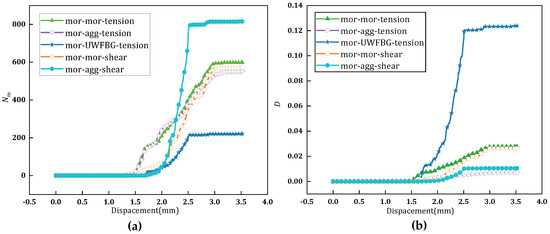
Figure 4.
Curve diagram of microcrack quantity and damage degree varying with loading displacement for different interfaces: (a) Microcrack number; (b) Damage degree.
To determine the damage degree of each interface within this asphalt mixture, an equation calculating the damage was proposed based on the microcrack number in this study, which is as follows:
where D denotes the degree of interface damage; Nm is the number of microcracks at different interfaces; Nc represents the total number of contacts between different components.
The calculated results by Equation (1) are shown in Figure 4b. The damage degree of each interface with displacement is also divided into three stages. The damage does not occur within this asphalt mixture when the loading displacement is less than 1.4 mm. Once the displacement exceeds 1.4 mm, the damage to all interfaces shows a gradual increase trend. Especially, for the tension condition of mor-UWFBG, beyond a displacement of 1.4 mm, both the damage degrees undergo a sudden surge, indicating a catastrophic failure mode induced by the rapid and massive initiation of microcracks under this specific condition. In terms of coupling between interface and loading modes, its order from large to small is as follows: mor-UWFBG-tension > mor-mor-tension > mor-mor-shear > mor-agg-shear > mor-agg-tension. The damage at the interface between mortar and UWFBG is the most serious compared to other interfaces, contrary to the order of microcrack number. Comparative analysis demonstrates that the tensile performance of the UWFBG interface is prone to triggering concentrated damage, and the interface presents higher failure sensitivity under tensile loading. This means that the interface between mortar and UWFBG is the most vulnerable location to damage within this asphalt mixture.
To further analyze the evolution mechanism of interface damage, a comparative change index in interface damage was proposed, as follows:
where ΔD represents the comparative change in interface damage; DUWFBG denotes the tension damage degree of the mor-UWFBG interface; Di indicates the tension damage degree of the interface between mortar and mortar or aggregate; and i is 1 or 2, D1 indicates the tension damage degree of the interface between mortar and mortar when i = 1, D2 indicates the tension damage degree of the interface between mortar and aggregate when i = 2.
Based on the damage degree varying with loading displacement for different interfaces, the comparative change in interface damage was calculated. A comparative analysis of the evolution of interface damage with displacement for different types of microcracks was conducted, as shown in Figure 5. It can be found that the law of comparative damage change with displacement is divided into five stages: zero, stable negative value, change dramatically, decrease rapidly and stable positive value. In the first stage (0–1.04 mm or 1.33 mm), there is no damage at all three interfaces (mor-UWFBG interface, mor-mor interface, mor-agg interface). In the second stage (1.04 mm or 1.33 mm–1.65 mm), the damage at the mor-UWFBG interface is smaller than that at the mor-mor and mor-agg interfaces. During this phase, microcracks begin to form within the specimen’s matrix, but no cracks appear at the sensor locations. In the third stage (1.65 mm–2.5 mm), the damage at the mor-UWFBG interface is greater than that at mor-mor and mor-agg interfaces, and this difference increases dramatically with displacement. This means that the damage development at this stage is mainly contributed by the damage at the mor-UWFBG interface. This phenomenon reveals that the embedding of the UWFBG induces pronounced stress concentration at the mor-UWFBG interface. As microcracks propagate within the asphalt mixture, separation happens at the junction between the UWFBG and the asphalt mixture, which directly accounts for the anomalously high damage degree observed in the mor-UWFBG-tension curve in Figure 4b. In this fourth stage (2.5 mm–3 mm), the comparative damage change values decrease rapidly. This may be due to the stabilization of the damage at the mor-UWFBG interface, while these damages at mor-mor and mor-agg interfaces are rapidly increasing. This means that the damage development at this stage is mainly contributed by these damages at mor-mor and mor-agg interfaces. In this fifth stage (above 3 mm), there is a constant comparative damage change value. The damages at all three interfaces have reached a maximum value.
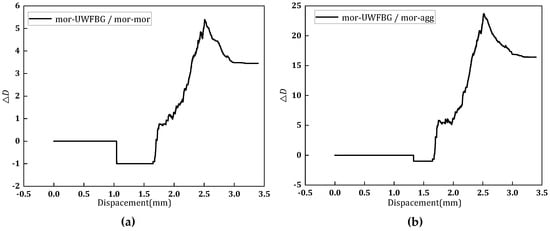
Figure 5.
Comparative changes of these damage degrees between various interfaces: (a) The comparative change between tension damages of mor-UWFBG and mor-mor; (b) The comparative change between tension damages of mor-UWFBG and mor-agg.
In summary, the damage degree, microcrack quantity and comparative damage change for the interface between mortar and UWFBG are negligible when the loading displacement is less than 1.65 mm. When the displacement exceeds 1.65 mm, however, these values increase dramatically, reflecting the development of the interfacial debonding between mortar and UWFBG. The underlying mechanism of this phenomenon lies in the stiffness mismatch between the UWFBG and asphalt mortar: this mismatch amplifies local stress at the interface, leading to accelerated interfacial deformation and damage evolution that outpaces the damage progression of the bulk asphalt mixture. This finding is consistent with the conclusion from Li et al. [29] that stress concentration at the sensor-matrix interface is the primary cause of sensor performance degradation, and further refines the critical displacement (1.65 mm) for the initiation of concentrated damage at the UWFBG-asphalt mortar interface under tensile loading that was not quantified in the previous DEM study [27]. Meanwhile, unlike the study by Duan et al. [30], which only reported the overall structural strength reduction caused by sensor embedding, this study further clarifies that the non-main damage interface (mor-UWFBG) is the most vulnerable to tensile damage due to stress concentration, which explains the monitoring signal distortion of UWFBG in engineering practice from a meso-mechanical perspective. These findings also complement the research by Zhang et al. [31] on fiber optic sensor-asphalt concrete interface modeling, by providing experimental and numerical evidence for the tensile damage sensitivity of the UWFBG-specific interface. These findings indicate that enhancing interfacial bonding performance can improve the deformation compatibility between the sensor and the asphalt matrix, thereby mitigating monitoring deviation and elevating the measurement accuracy of the UWFBG sensor.
4.2. The Evolution Process of Internal Strain with Asphalt Mixture
This section focuses on the application of UWFBG sensors in the long-term monitoring of pavement structures, adopting the DEM to conduct a simulation study on the relationship between UWFBG-measured strain and crack width. In the DEM simulation, cracks are directly characterized by the fracture of inter-particle bonds: when the stress acting on the bond between adjacent particles reaches the strength limit, the bond fractures to generate microcracks, while macro-cracks gradually evolve through the initiation, aggregation, and penetration of numerous microcracks. The method for monitoring crack width involves using the asphalt mixture particles near the lower surface of the marked sensor as a reference and measuring the spacing between adjacent particles on both sides of the crack. For strain monitoring, particles situated 2 mm (A1, the top position of UWFBG), 5 mm (A2, the middle position of UWFBG), and 8 mm (A3, the bottom position of UWFBG) below the center line are selected as marker points, with the monitoring segment length set to 30 mm. The marker positions are depicted in Figure 6.
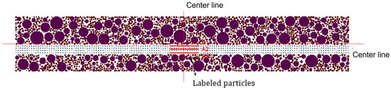
Figure 6.
Schematic diagram of marker distribution for strain monitoring.
During the crack propagation process of UWFBG sensor-free asphalt mixture specimens, the strains at the three monitoring points all exhibit a uniform linear growth pattern with the increase in crack width (as shown in Figure 7a). Although differences exist in the strain growth slopes among the three points, the overall deformation mode remains consistent. This phenomenon indicates that in the absence of external sensing elements, the strain of the asphalt mixture presents a monotonically increasing linear relationship with crack width. During crack propagation, stress is uniformly transmitted along the aggregate-asphalt mortar interface, leading to a stable linear correlation between strain and crack width growth. No obvious stress concentration or abrupt deformation regions are observed. This regularity can serve as a baseline, providing a reference for comparative analysis of the differences in mechanical behaviors after the introduction of UWFBG.
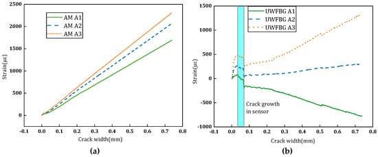
Figure 7.
Variation diagram of strain with crack width: (a) Asphalt mixture; (b) Asphalt mixture containing UWFBG.
The strain-crack response of the asphalt mixture with UWFBG is divided into three stages, reflecting crack initiation, propagation and interface interaction between UWFBG and the mixture. Strain shifts from initial linear growth to nonlinear attenuation, revealing material damage and interface debonding mechanisms. Stage 1 (0–0.03 mm Crack width): Cracks initiate but do not reach the position of UWFBG. All three strain curves show large growth slopes, as the mixture exhibits significant stress concentration. Strains develop rapidly in distinct directions due to initial stress differences, reflecting the mixture’s local stress response before cracks touch UWFBG. Stage 2 (0.03–0.07 mm Crack width): In the corresponding blue area, strain development changes noticeably. The strain of A3 maintains growth at a reduced rate, that of A2 growth flattens, and the negative strain of A1 growth slows. This is because the optical cable participates in stress transmission when cracks reach 0.03 mm, altering stress distribution and alleviating stress concentration. Stage 3 (Crack width > 0.07 mm): All strain curves show decreased growth slopes. The strain of A3 grows positively at a much slower rate, that of A2 has slow positive strain growth, and the negative strain of A1 growth decelerates. Crack penetration triggers the debonding of the UWFBG -mixture interface, reducing stress transmission efficiency. Unresolved interface stress leads to slower strain growth, indicating the impact of interface debonding on mechanical properties, as shown in Figure 7b. In summary, the strain-crack width response of asphalt mixtures shows distinct stage characteristics before and after the embedding of UWFBG sensors, which is a key meso-mechanical law that has not been systematically revealed in previous studies on UWFBG pavement monitoring. The critical crack width of 0.03 mm, where the UWFBG begins to participate in stress transmission, and 0.07 mm, where interfacial debonding dominates strain evolution, are two key thresholds not identified in previous finite element simulation studies [22] on sensor-asphalt mixture interaction.
4.3. The Construction of Model Monitoring Crack Width
According to the above sections, the relative displacement of marked particles was calibrated by the discrete element simulation. Then, the quantitative characterization of crack width was realized. A numerical model was presented to quantify the relationship between crack width and the UWFBG peak strain during combined deformation in asphalt mixtures. The numerical relationship is as follows:
where y is the crack width at the contact position between the asphalt mixture and the lower surface of the sensor, mm; εp is the peak strain value of UWFBG; εr is the peak strain at the crack initiation point of UWFBG, with a value of 248 μɛ; a and b are variable parameters related to material properties. Under the test conditions in this study, the values of parameters are acquired based on the data statistics and curve fitting, and the values are shown in Figure 8.
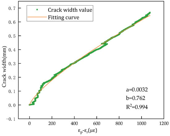
Figure 8.
Relationship for correcting measurement error.
As illustrated in Figure 8, the strain difference increases from approximately 0 μɛ to 1075.9 μɛ as the crack width expands from 0 mm to 0.66 mm. This variation exhibits a strong two-stage linear correlation. A non-linear Equation (3) was used to fit these results. The result exhibited a high goodness of fit (R2 = 0.994). This validates the feasibility of UWFBG sensing for quantitative measurement of crack widths in asphalt mixtures, and it has a high sensitivity and reliability. The established measurement range (0–0.66 mm) covers the critical stage from crack initiation to early propagation in asphalt pavements. To sum up, the UWFBG enables one to capture the crack initiation and its early propagation.
5. Conclusions
Based on the discrete element method, this study examined the interaction between UWFBG and asphalt mixtures. It investigated the synergy deformation of the mixture under loading. The following conclusions are drawn:
- (1)
- The number of microcracks within the asphalt mixture containing UWFBG during the bending test undergoes three stages with displacement: crack-free, increases rapidly, maximum stable. This number at the mor-UWFBG interface under a tension loading mode is the smallest, meaning that the interface is not the main damage location of this asphalt mixture, but may be the one affecting the monitoring of UWFBG.
- (2)
- The damage degree based on the number of microcracks was proposed. The damage degree of each interface during the bending test undergoes three stages with displacement. Compared to other interfaces and loading modes, this damage at the mor-UWFBG interface under a tension loading mode is the largest, contrary to the number of microcracks. This demonstrates that the tensile strength of the mor-UWFBG interface is prone to triggering concentrated damage, and a higher failure sensitivity exists at this interface under this loading, so this interface is the most vulnerable location to damage within this asphalt mixture.
- (3)
- The comparative change in interface damage was proposed. The comparative damage change undergoes five stages: zero, stable negative value, change dramatically, decrease rapidly and stable positive value. This further refines the contribution of the mor-UWFBG interface throughout the entire damage evolution stage of the asphalt mixture.
- (4)
- The strain response of UWFBG within the asphalt mixture undergoes three stages with crack width: crack initiation, crack propagation, and interface debonding. This strain shifts from initial linear growth to nonlinear attenuation. This is attributed to the fact that UWFBG participates in the transmission of stress when a crack propagates to the UWFBG; the stress concentration is thus alleviated, and its distribution is altered.
- (5)
- A numerical model to correct the errors of synergistic deformation between the asphalt mixture and UWFBG. The model can be used to capture crack initiation and its early propagation.
- (6)
- The simulated and monitoring models presented in this study can be used to analyze interfacial damage and correct the errors of synergistic deformation between the asphalt mixture and UWFBG. However, such factors as the viscoelastic properties of the asphalt mixture, temperatures and mixture types are not considered in this approach. They should be the focus of future research. In addition, the macro-scale mechanical predictions based on meso-scale phenomena are a significant issue. This is of particular interest to road engineers. Therefore, this issue should be studied further in detail to provide instructive recommendations for the monitoring of the cracks within asphalt pavements.
Author Contributions
Conceptualization, Z.H. and Y.J.; Methodology, D.D.; Software, D.D., Y.L. and X.L.; Validation, D.D. and Y.J.; Formal analysis, Z.H. and X.L.; Investigation, D.D.; Resources, Y.J.; Data curation, D.D. and X.L.; Writing—original draft preparation, D.D. and Y.J.; Writing—review and editing, Y.J., D.D. and Y.L.; Visualization, D.D.; Supervision, Y.J.; Project administration, Y.J. and Z.H.; Funding acquisition, Y.J. and Z.H. All authors have read and agreed to the published version of the manuscript.
Funding
This research was funded by the Technology Project of Hebei Expressway Group Limited (111007-09-2024-0093). The authors gratefully acknowledge their financial support.
Institutional Review Board Statement
Not applicable.
Informed Consent Statement
Not applicable.
Data Availability Statement
The data presented in this study are available on request from the corresponding author (The data are not publicly available due to privacy).
Acknowledgments
The useful support provided by the Hebei Key Laboratory of Traffic Safety and Control (Shijiazhuang Tiedao University) is acknowledged.
Conflicts of Interest
Zengqing Hua and Xiuying Luo were employed by the company Jinghu Branch, Hebei Expressway Group Limited. The remaining authors declare that the research was conducted in the absence of any commercial or financial relationships that could be construed as a potential conflict of interest.
Abbreviations
The following abbreviations are used in this manuscript:
| UWFBG | Ultra-weak Fiber Bragg Grating |
| DEM | Discrete element method |
References
- Song, S.L.; Hou, Y.; Guo, M.; Wang, L.B.; Tong, X.L.; Wu, J.F. An investigation on the aggregate-shape embedded piezoelectric sensor for civil infrastructure health monitoring. Constr. Build. Mater. 2017, 131, 57–65. [Google Scholar] [CrossRef]
- Janabi, A.J.A.; Obaid, H.A. Analysis of the impact of overloading for trucks on the design life of flexible pavement. IOP Conf. Ser. Earth Environ. Sci. 2024, 1374, 012089. [Google Scholar] [CrossRef]
- Chupin, O.; Piau, J.M.; Chabot, A. Evaluation of the structure-induced rolling resistance (SRR) for pavements including viscoelastic material layers. Mater. Struct. 2013, 46, 683–696. [Google Scholar] [CrossRef]
- Zhang, Y.N.; Zhou, L.; Qiao, D.; Liu, M.Y.; Yang, H.Y.; Meng, C.; Miao, T.; Xue, J.; Yao, Y.M. Progress on optical fiber biochemical sensors based on graphene. Micromachines 2022, 13, 348. [Google Scholar] [CrossRef]
- Jiang, J.P.; Yue, L.; Li, S.; Liu, F.; Pan, J.J.; Gan, W.B. Application of ultra-weak fiber Bragg grating sensing array to road vehicle detection. Measurement 2025, 241, 115647. [Google Scholar] [CrossRef]
- Luo, Z.H.; Hua, P.; Xu, B.; Wang, Y.M.; Ye, Y. Ground surface displacement monitoring method based on ultra-weak fiber Bragg grating array. J. Saf. Sci. Technol. 2022, 18, 18–24. [Google Scholar]
- Wang, H.G.; Gong, H.L.; Zhang, J.C.; Zhu, L.; Ning, D.; Zhou, C.F.; Yan, X.G. Layered monitoring of ground subsidence based on ultra-weak FBG sensing technology: A case study in Gaoyang county, China. Micromachines 2025, 16, 1380. [Google Scholar] [CrossRef]
- Li, S.; Qiu, Y.; Nan, Q.M.; Gan, W.B.; Jiang, J.M. A method for identifying and locating illegally invading subway lines by drilling rigs based on ultra-weak Bragg fiber optic grating sensing array. J. Vib. Shock 2022, 41, 202–207. [Google Scholar]
- Jia, Y.S.; Wang, S.Q.; Huang, A.Q.; Gao, Y.; Wang, J.S.; Zhou, W. A comparative long-term effectiveness assessment of preventive maintenance treatments under various environmental conditions. Constr. Build. Mater. 2020, 273, 121717. [Google Scholar] [CrossRef]
- Chen, G.; Rui, G.; Lei, L.Y.; Li, X.; Pei, J.Z. Exploring the unjamming transition of meso-mechanical shear failure behavior in asphalt mixture. Comput.-Aided Civ. Infrastruct. Eng. 2025, 40, 4929–4945. [Google Scholar] [CrossRef]
- Jia, Y.S.; Li, Y.X.; Wu, Z.Y.; Si, C.D.; Zhang, J.P.; Wang, S.Q.; Gao, Y.; Li, Z.R.; Wei, Z.Y. Evaluation of filler particle size effect of dynamic modulus for asphalt mastic with a new combined micromechanics approach. Constr. Build. Mater. 2025, 477, 141335. [Google Scholar] [CrossRef]
- Wei, Z.Y.; Filonzi, A.; Baumgardner, G.; Bhasin, A. Evaluating the long-term cracking and oxidation resistance of asphalt binder incorporating bio-based additives. Constr. Build. Mater. 2026, 512, 145398. [Google Scholar] [CrossRef]
- Han, D.D.; Chen, S.W.; Tang, D.; Liu, G.Q.; Zhao, Y.L.; Xu, N. Optimization of asphalt pavement strain measurement across a wide temperature range. Constr. Build. Mater. 2025, 464, 140198. [Google Scholar] [CrossRef]
- Liu, W.Q.; Wang, H.P.; Zhou, Z.; Xing, X.Y.; Cao, D.D.; Jiang, Z. Optical fiber-based sensors with flexible encapsulation for pavement behavior monitoring. Struct. Control Health Monit. 2015, 22, 301–313. [Google Scholar] [CrossRef]
- Lau, K.T.; Chan, C.C.; Zhou, L.M.; Wei, J. Strain monitoring in composite-strengthened concrete structures using optical fiber sensors. Compos. Part B Eng. 2001, 32, 33–45. [Google Scholar] [CrossRef]
- Hu, J.; Qian, Z.D.; Chen, L.L. Fracture behavior of epoxy asphalt pavement on steel bridges based on optical fiber sensing technology and numerical simulation. J. Wuhan Univ. Technol.-Mater. Sci. Ed. 2014, 29, 858–862. [Google Scholar] [CrossRef]
- Hou, Z.J.; Cao, D.G.; Peng, P. Analysis of strain transfer characteristics of fiber Bragg gratings for asphalt pavement health monitoring. Materials 2025, 18, 3489. [Google Scholar] [CrossRef]
- Chapeleau, P.X.; Blanc, J.; Hornych, P.; Gautier, J.L.; Carroget, J. Assessment of cracks detection in pavement by a distributed fiber optic sensing technology. J. Civ. Struct. Health Monit. 2017, 7, 459–470. [Google Scholar] [CrossRef]
- Huang, J.L.; He, Y.R.; Wang, X.L. Research on distributed strain sensing optical cable based on UWFBG. Transduc. Microsyst. Technol. 2025, 44, 14–18+23. [Google Scholar]
- Liu, H.; Li, Y.X.; Jia, Y.S.; Li, J.Z.; Zhang, J.P.; Wang, B.; Liu, W. Research on the influence of built-in strain sensor on the mechanical response of asphalt mixture. Highway 2025, 70, 22–30. [Google Scholar]
- Tian, G.L.; Dong, Z.J.; Hu, Q.L.; Tan, Y.Q. Analysis of coordination between asphalt mixture and fiber Bragg grating sensor. J. Harbin Inst. Technol. 2009, 41, 73–76. [Google Scholar]
- Han, D.D.; Tang, D.; Liu, G.Q.; Zhao, Y.L. Measurement accuracy evaluation and optimization of embedded strain sensor for asphalt mixture: Laboratory tests and finite element simulation. Smart Mater. Struct. 2024, 33, 075025. [Google Scholar] [CrossRef]
- Liu, G.Q.; Gao, Y. Study on micro-mechanical mechanisms of aggregate skeleton based on three-dimensional discrete element method and force chain theory. Int. J. Pavement Eng. 2025, 26, 2504657. [Google Scholar] [CrossRef]
- Liu, G.Q.; Huang, T.; Liu, Z.J.; Jiang, N. Evaluation of affinity between aggregate skeleton topology and rutting performance of asphalt mixture based on network theory. Constr. Build. Mater. 2025, 458, 139647. [Google Scholar] [CrossRef]
- Xue, B.; Que, Y.; Pei, J.Z.; Ma, X.Y.; Wang, D.; Yuan, Y.; Zhang, H. A state-of-the-art review of discrete element method for asphalt mixtures: Model generation methods, contact constitutive models and application directions. Constr. Build. Mater. 2024, 414, 134842. [Google Scholar] [CrossRef]
- Yan, Z.Y.; Lian, J.H.; Zhang, J.H.; Song, D.M.; Zhao, G.F. Research on vehicle-asphalt pavement interaction and micro-structure by discrete element method. Mech. Adv. Mater. Struct. 2022, 29, 6803–6813. [Google Scholar] [CrossRef]
- Li, Z.P.; Han, X.; Zhang, Z.L.; Zhao, J.Y.; Tian, S.C.; Gao, M.; Wang, A.N. Numerical analysis on mechanical properties of asphalt road with intelligent sensor. China J. Highw. Transp. 2023, 36, 49–57. [Google Scholar]
- Liu, L.; Li, L.; Liu, Z.H.; Fu, S.F.; Li, W.B.; Pan, H.X. Influence of built-in strain sensor on the mechanical properties of asphalt mixture. Chin. J. Eng. 2025, 47, 179–194. [Google Scholar]
- Li, W.B.; Liu, L.; Liu, Z.H.; Pan, B.Y.; Li, L. Micromechanical behavior of asphalt mixtures with embedded strain sensors. J. Railway Sci. Eng. 2026, 1–14. [Google Scholar] [CrossRef]
- Duan, L.W.; Peng, J.H.; Xiong, J.; Fu, S.F.; Li, W.B. Study on the interaction influence of strain sensor and asphalt mixture based on discrete element method. J. Municip. Technol. 2024, 42, 98–105. [Google Scholar]
- Zhang, X.F.; Qian, Z.D.; Chen, L.L.; Zhang, M. Numerical simulation for synergetic deformation of optical fiber sensor and asphalt mixture. KSCE J. Civ. Eng. 2019, 23, 3075–3087. [Google Scholar] [CrossRef]
- Cao, J.X. Bridge structure deformation monitoring method based on ultra-weak fiber Bragg grating array and its application. World Bridges 2025, 53, 102–107. [Google Scholar]
- GBT7424.21-2021; Optical Fiber Cable Generic Specification—Part 21: Basic Optical Cable Test Procedures—Mechanical Test Methods. Standards Press of China: Beijing, China, 2021.
- JTG E42-2005; Test Methods of Aggregate for Highway Engineering. Ministry of Transport of the People’s Republic of China: Beijing, China, 2005.
- JTG 3410-2025; Standard Test Methods of Bitumen and Bituminous Mixtures for Highway Engineering. Ministry of Transport of the People’s Republic of China: Beijing, China, 2025.
- JTG F40-2004; Technical Specifications for Construction of Highway Asphalt Pavements. Ministry of Transport of the People’s Republic of China: Beijing, China, 2004.
- Zhang, D.C.; Gong, Z. Research development of discrete element method in pavement materials application. J. Xuzhou Inst. Technol. (Nat. Sci. Ed.) 2020, 35, 41–44. [Google Scholar]
- Ding, X.H.; Huang, F.Y.; Rath, P.; Ye, Z.Y.; Buttlar, W.G.; Ma, T. Comparative fracture resistance assessment of rubber modified asphalt mortar based on meso-and macro-mechanical analysis. Int. J. Pavement Eng. 2023, 24, 2265032. [Google Scholar] [CrossRef]
- Wang, J.Y. Research on Fracture Behavior of Epoxy Asphalt Concrete Used for Steel Bridge Wearing Course Under Meso-Scale. Ph.D. Thesis, Southeast university, Nanjing, China, 2013. [Google Scholar]
- Cao, Y.J.; Zeng, J.; Muhsen, S.; Ponnore, J.J.; Ali, H.E.; Assilzadeh, H.; Gutierrez, J.E. Particle dynamics and void distribution in asphalt mixtures: Discrete element modeling. Powder Technol. 2026, 467, 121486. [Google Scholar] [CrossRef]
- Chen, J.; Huang, X.M. Virtual fatigue test of asphalt mixture based on discrete element method. J. Jilin Univ. (Eng. Technol. Ed.) 2010, 40, 435–440. [Google Scholar] [CrossRef]
- Gai, H.E. Dynamic Response of Asphalt Pavement Under Vehicle-Road Interaction Based on Discrete Element Method. Master’s Thesis, Shijiazhuang Teidao University, Shijiazhuang, China, 2021. [Google Scholar]


Disclaimer/Publisher’s Note: The statements, opinions and data contained in all publications are solely those of the individual author(s) and contributor(s) and not of MDPI and/or the editor(s). MDPI and/or the editor(s) disclaim responsibility for any injury to people or property resulting from any ideas, methods, instructions or products referred to in the content. |
© 2026 by the authors. Licensee MDPI, Basel, Switzerland. This article is an open access article distributed under the terms and conditions of the Creative Commons Attribution (CC BY) license.