Abstract
Plasma regeneration was investigated as a means of regenerating microstructures on biosensors for repeated use. These microstructures were based on the deposition of suspensions containing polymer microspheres. While this method provides a simple way to structure surfaces, obtaining regular structures in a reproducible way remains a challenge. Therefore, it would be advantageous to be able to reuse regular structures, which requires regeneration. To investigate this concept, surface acoustic wave (SAW) resonators were structured using 5 µm and 20 µm polystyrene microspheres and coated with parylene C to stabilize the particle structures. After use in bioanalytical experiments, the biological residues and the parylene C cover layer were removed with plasma, and a new parylene C layer was added. Both atmospheric and low-pressure plasma were tested for regeneration. As a result, the low-pressure plasma was to be preferred because it did not damage the transducer structures on the SAW resonators, unlike the atmospheric plasma. Water contact angle measurements and transmission spectra recorded with a network analyzer confirmed that freshly prepared and regenerated structured SAW resonators coated with parylene C exhibited similar wetting properties and resonance parameters. Therefore, plasma regeneration is an effective way to enable the reuse of perfectly structured SAW resonators.
1. Introduction
The implementation of structures on flat surfaces increases the total surface area and changes the wettability of the surface. These and other effects influence the binding of molecules on the surface and, hence, the signal responses of surface-based detectors, such as sensors and biosensors [1,2,3]. A simple method of introducing microstructures onto surfaces is to deposit microparticles from corresponding suspensions and allow them to self-assemble into two- or three-dimensional structures. This has been applied, among others, for creating particle arrays from microgel particle dispersions and for particulate graphite coatings for use in gas sensors [4,5,6].
However, the reproducible preparation of regular structures remains challenging. Firstly, the heterogeneous nature of the suspensions makes reproducible portioning difficult. Secondly, as the solvent evaporates from the surface, the particles move toward the edge, forming a ring-like structure known as the “coffee-ring effect”. Various measures have been developed to control number and arrangement of the particles, including the use of additives in the suspensions, increasing surface wetting, and applying templates on the surfaces [5,7,8,9,10]. Nevertheless, from a sustainability perspective, it would be advantageous if a perfectly structured layer could be used for multiple measurements. For this, it may be necessary to remove any layers deposited on the structures in preparation of or during the experiment. In the case of biosensor measurements, for instance, this would mean removing the sensing layer and any binding molecules to obtain the pure structure for the next run.
The application of physical plasma is a fast, widely applicable, and mostly residue-free method of cleaning surfaces, including the regeneration of biosensors. In chemical laboratories, artificial plasma is primarily excited by discharge ionization, which can be produced at either atmospheric or low pressure. Plasma at atmospheric conditions is easier to apply than low-pressure plasma because the latter requires a vacuum setup. However, while the density of active particles is reduced in low-pressure plasma, their mean free path is extended, which increases the cleaning depth, albeit at reduced intensity [11,12,13,14]. While removing unwanted components and contaminants with plasma is comparatively easy, preserving the surrounding materials requires careful consideration of the plasma parameters. Most importantly, the core material must remain intact; typically, only an insignificant amount can be removed without damaging the device. Furthermore, when metallic micro- or nanoelectrodes are included, such as interdigitated electrodes (IDEs), they may be damaged by plasma, even if they are covered by an insulation layer. In plasma, the electric field is concentrated at the edges of the electrode fingers. This can result in a field strength that exceeds the dielectric strength of the surrounding medium, which can lead to a flashover or short circuit. This can cause permanent damage to the electrode material [15,16,17,18].
Sensors or biosensors using IDEs or interdigital transducers (IDTs) include devices with electrochemical, optical, and piezoelectric detection [19], such as surface acoustic wave (SAW) resonators. SAW resonators have successfully been applied in a multitude of gas sensing and biosensing applications. Like other piezoelectric sensor devices, SAW resonators convert and detect electrical energy and acoustic (i.e., mechanical) waves. The wave on the piezoelectric crystal is both excited and received by IDTs. The SAW resonator only allows the transmission of signals within one frequency band, so it can also be classified as a bandpass filter [20,21,22,23,24]. In a previous approach, SAW resonators were structured by depositing polystyrene microspheres onto the surface. A parylene C (poly(2-chloro-para-xylylene)) cover layer was then deposited on the structured layer via chemical vapor deposition (CVD) in order to stabilize the particle structure. These structured SAW resonators were applied in bioanalytical measurements, mainly for protein adsorption [25].
In this study, SAW resonators with structured surfaces that had been used in bioanalytical measurements were regenerated by removing the biolayer and the parylene C cover layer using plasma. Then, a new parylene C cover layer was deposited. Both atmospheric plasma and low-pressure plasma were tested for treating these structured SAW resonators. Atmospheric plasma was applied with an easy-to-handle, handheld device exploiting the direct electrical discharge at an open piezoelectric transformer. This method produces high electric field strengths with low power consumption and a plasma temperature of around 50 °C [26]. Low-pressure plasma was applied by a tabletop instrument using a radio frequency (RF) oscillating electric field that was inductively generated in the reaction chamber at reduced pressure [27]. Water contact angles were determined to compare the wetting properties of freshly prepared and regenerated structured SAW resonators coated with parylene C. Additionally, transmission spectra were recorded with a network analyzer to determine the resonance parameters of freshly prepared and regenerated structured SAW resonators coated with parylene C. Finally, a preliminary protein adsorption experiment was performed on a freshly prepared and a regenerated structured SAW resonator.
It was shown that the low-pressure RF plasma did not damage the IDTs of the structured SAW resonators, in contrast to the atmospheric plasma. Furthermore, similar wetting properties and resonance parameters were obtained for freshly prepared and for regenerated structured SAW resonators after coating with parylene C. The regeneration did not affect the suitability of the structured SAW resonators for use in protein adsorption measurements.
2. Materials and Methods
2.1. SAW Resonators
Shear horizontal SAW resonators, type SR062, were purchased from SCD (SAW Components Dresden, Dresden, Germany). The two-port resonators consisted of 36°YX-LiTaO3 piezo crystals with IDTs, reflective fingers, and contact pads for high frequency coupling and ground made of gold. The size of the crystals was 4 mm × 4 mm with a thickness of 0.35 mm. The acoustic aperture of the IDTs was 0.2 mm. The frequency of operation was specified by the manufacturer as 427.8 MHz with an insertion loss of −9 dB.
2.2. Parylene C Coating
Parylene C layers were applied by CVD using parylene C dimer (di(2-chloro-para-xylylene)) and a commercial parylene deposition system (type Labcoter 1, PDS 2010), as described previously [28]. Dimer and device were purchased from Specialty Coating Systems, Indianapolis, IN, USA. The CVD process was based on the sublimation and subsequent pyrolysis of the dimer. The resulting monomer polymerized at room temperature on devices provided in an evacuated deposition chamber. The layer thickness was determined by a quartz crystal microbalance (QCM) sensor integrated in the deposition chamber. QCM sensor and readout controller were obtained from Leybold Inficon, East Syracuse, NY, USA.
2.3. Plasma Treatment
Structured SAW resonators coated with parylene C were treated with atmospheric plasma or with low-pressure plasma. Atmospheric plasma was applied by the PiezoBrush PZ3, a handheld device purchased from Relyon Plasma GmbH, Regensburg, Germany, and the corresponding standard module for non-conducting surfaces. The module was held at a distance of 5 mm from the SAW resonator surface for 15 s, while the PiezoBrush was operated at the lowest possible power (4 W). Low-pressure plasma was applied by the Basic Plasma Cleaner type PDC-32G-2, a tabletop instrument supplied by Harrick Plasma, Ithaca, NY, USA. A vacuum pump was connected (Edwards High Vacuum, Crawley, Sussex, UK) with a maximum pumping speed of 0.34 m3/min to obtain the low pressure. Up to three SAW resonator devices were inserted into the reaction chamber, and the pressure was reduced to 0.13 hPa. A summary of the plasma parameters is provided in Table 1.

Table 1.
Plasma parameters used in this study. Device-related parameters were obtained from the manufacturers’ specifications.
Further details regarding plasma treatment for structuring and for regeneration are described in the sections below. In brief, low-pressure plasma for surface activation, as required for the structuring, was applied for 15 s at 11 W. This step cleans and cracks the topmost layers, producing functional groups [29]. Low-pressure plasma for regeneration was applied for 5 min at 18 W to remove the biolayer and the parylene C cover layer.
2.4. Structuring
Polystyrene particles (microspheres) of 5 µm and 20 µm were purchased from Sigma-Aldrich, Taufkirchen, Germany. According to the manufacturer’s specifications, the calibrated particle diameter of the 5 µm particles (PN 79633) was 5.05 µm, determined with a standard deviation of 0.16 µm and a coefficient of variation (CV) of 3.1%. The calibrated particle diameter of the 20 µm particles (PN 74491) was 19.82 µm, determined with a standard deviation of 0.34 µm and a CV of 1.7%. The 5 µm particles and the 20 µm particles were provided as aqueous suspensions with 10% solids and diluted with double-distilled water to working concentrations of 5 mg/mL and 30 mg/mL, respectively. SAW resonators coated with 0.05 µm parylene C were activated with the tabletop plasma instrument (described above) in order to obtain a hydrophilic surface. The power applied to the RF coil was set to 11 W, and the plasma treatment was 15 s. Immediately afterwards, a 5 µL drop of diluted particle suspension was applied on the respective activated surface and left to dry overnight. In a last step, the particles were fixed with another layer of 0.05 µm parylene C. Structured SAW resonators were chosen for further use if they exhibited a particle monolayer with no or only minor defects.
2.5. Regeneration of Structured Surfaces
Structured SAW resonators that had been applied earlier in bioanalytical measurements [25] were regenerated by low-pressure plasma, using the tabletop instrument described above. The power applied to the RF coil was set to the highest level, i.e., 18 W, and the plasma treatment was 5 min to remove biolayer and parylene C cover layer. After the plasma regeneration, a new cover layer of 0.05 µm parylene C was applied, as described above.
2.6. Contact Angle Measurements
Water contact angles were determined by the sessile drop method using a contact angle measurement microscope (type 20668; obtained from Erma, Tokyo, Japan).
2.7. Transmission Spectra
SAW resonators were individually inserted into a flow cell enabling both electrical and fluidic contacting of the devices, as described previously [21]. The flow cell with SAW resonator was connected to a vector network analyzer, type HP 8712C RF (Hewlett Packard, Palo Alto, CA, USA), and filled with phosphate-buffered saline (PBS). PBS was purchased from Sigma-Aldrich, Taufkirchen, Germany (PN P4417). After a few minutes with no flow in the flow cell, the equilibrium was reached and the transmission spectrum remained constant. At this point the S21 parameters were extracted, i.e., maximum in the attenuation spectrum, corresponding frequency (i.e., resonance frequency), and phase at this frequency. Figure S1 shows an example of the procedure for determining the resonance parameters from the transmission curves.
2.8. Protein Adsorption Measurement
SAW resonators that were structured with polystyrene particles and coated with a parylene cover layer were activated individually with the tabletop plasma instrument as described in Section 2.4. Immediately afterwards, the activated SAW resonator was inserted into the flow cell described in Section 2.7. and connected to a flow injection analysis (FIA) system, as described previously [21,30]. In brief, the FIA system was equipped with two peristaltic pumps (Ismatec, Wertheim, Germany) and a six-port sample injection valve (Besta-Technik, Wilhelmsfeld, Germany). The injection valve allowed switching between carrier medium (PBS) or sample driven through the flow cell and, hence, across the SAW resonator. The flow rate was set to 0.05 mL/min. Protein samples contained human serum albumin (HSA), purchased from Merck Chemicals GmbH, Darmstadt, Germany (PN 126658). HSA was dissolved at a concentration of 4 mg/mL in PBS. During a protein adsorption measurement, the protein sample was injected into the PBS carrier stream within 60–300 s. Before and after this injection interval, PBS was driven across the sensor.
The SAW resonator was integrated as the frequency-determining element into an oscillator circuit by means of the flow cell, as described previously [21,30,31]. The frequencies of the circuit, that correspond to the frequencies of the SAW resonator, were determined as difference to a reference resonator oscillating permanently at 433.9 MHz. Since this reference frequency was higher than the resonance frequencies of the SAW resonators (approximately 427 MHz), processes leading to a decrease in the SAW resonator frequencies, such as mass loading, resulted in increasing difference frequencies. Difference frequency curves were plotted to start at 0 Hz to optimize clarity. The frequency resolution was 1 Hz.
3. Results and Discussion
3.1. Evaluating the Plasma Treatment
The parylene C layer covering the structures, as well as the biolayer comprising a potential sensing layer and biomolecules resulting from the bioanalytical experiment, were to be removed to regenerate the structured SAW resonators. Plasma was chosen as a fast and mostly residue-free method to remove these layers. Both a handheld device providing atmospheric plasma and a tabletop instrument providing low-pressure plasma were available. In a preliminary test, parylene C-coated SAW resonators were treated shortly with both types of plasma in order to determine the impact of the respective plasma on the surface wetting and on the SAW resonators’ IDTs. The results are shown in Figure 1.
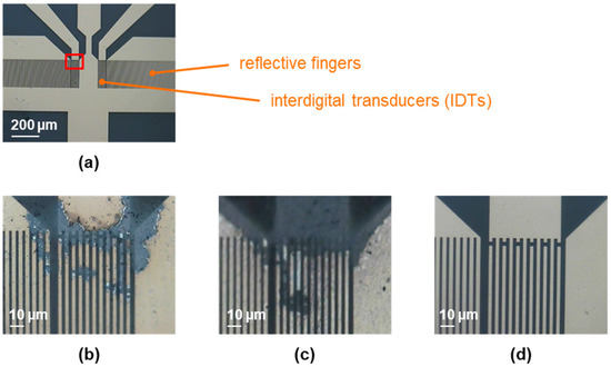
Figure 1.
Two-port SAW resonators, coated with 0.05 µm parylene C, before and after 15 s of plasma treatment, as described in Section 2.3 and Section 2.4. (a) Active part of a two-port SAW resonator device prior to plasma treatment. The red box highlights the area from which the following pictures were taken. (b) SAW resonator provided on a silicone pad after treatment with atmospheric plasma. (c) SAW resonator provided on a metal pad after treatment with atmospheric plasma. (d) SAW resonator treated with low-pressure plasma.
Before plasma treatment, the contact angles were above 80°, representing the water contact angle expected for parylene C [21]. The contact angles were reduced to values below 15° by 15 s of plasma treatment, regardless of which plasma was used. Therefore, the ability to activate the parylene C surface by breaking the molecular chains, resulting in a more hydrophilic surface upon reaction with air, was comparable for both types of plasma. However, as shown in Figure 1b, the atmospheric plasma damaged the IDTs, i.e., the electric field strength was too high for this resonator design and led to flashovers or similar issues. Placing the SAW resonator on a metal pad to discharge an excess of electrical energy did not improve the situation, as shown in Figure 1c. Applying the low-pressure plasma instead did not damage the IDTs (Figure 1d). The reduced density of active particles and, hence, reduced electric field strength, was sufficiently low to be compatible with the SAW resonator’s IDTs. Therefore, low-pressure plasma was used in subsequent experiments.
In the next step, low-pressure plasma was applied on a parylene C-coated structured SAW resonator to verify the removal of the parylene C from the surface, as well as future biolayers from bioanalytical experiments. Figure 2 shows a SAW resonator device with an insufficient particle structure that was used for parylene C removal tests. Parylene C was present as underlying and cover layers for the particle structure. Prior to plasma treatment, a scratch was deliberately made in the parylene C layers to enable easy observation of the removal process with a microscope (Figure 2 (left)).
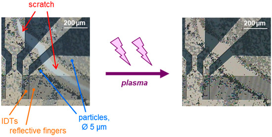
Figure 2.
Detail of a SAW resonator with an incomplete structure of 5 µm polystyrene microspheres that was coated with parylene C and exposed to low-pressure plasma for 5 min., as described in Section 2.5. Before plasma treatment, there is a scratch in the underlying and cover layers of parylene C (left). After plasma treatment, the scratch in the layers is no longer visible (right), suggesting that the most part of the parylene C is removed.
After applying the low-pressure plasma for 5 min at the highest level, the scratch in the parylene C layer was no longer visible (Figure 2 (right)). This indicates that the low-pressure plasma treatment was able to remove most of the 0.1 µm parylene C (i.e., underlying and cover layers, 0.05 µm each). This should be sufficient to remove the majority of the 0.05 µm cover layer from future structured SAW resonators [32], as well as any biolayers remaining from bioanalytical applications. Any potential residues would be in the nanoscale range and covered by a new parylene C cover layer, ensuring that the surface for subsequent measurements resembles that of newly microstructured and coated SAW resonators. This will be demonstrated in the following.
3.2. Wetting Behavior and Resonance Point of New and Regenerated SAW Resonators
Figure 3a,b show exemplary SAW resonators structured with 5 µm or 20 µm particles. Water contact angles on SAW resonators that were newly structured with 5 µm or 20 µm particles and coated with parylene C were determined (Figure 3c, Table S1). The SAW resonators were used in bioanalytical measurements, as described previously [25], then regenerated with low-pressure plasma, as described above, and coated with a new parylene C cover layer. Again, the contact angles were determined and compared to the contact angles obtained before the bioanalytical measurements as well as to those obtained with unstructured SAW resonators (Figure 3c, Table S1).
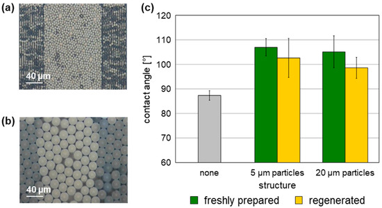
Figure 3.
Contact angles of unstructured and structured SAW resonators coated with a 0.05 µm parylene C cover layer. (a,b) Exemplary SAW resonators structured with 5 µm and 20 µm polystyrene microspheres, respectively. (c) Contact angles of six unstructured and six structured SAW resonators per particle diameter; the structures were freshly prepared or regenerated. Columns represent the means, and the error bars represent the sample standard deviations.
Contact angles obtained with structured SAW resonators were generally higher than those obtained with unstructured SAW resonators. However, no significant variation in contact angles considering the respective sample standard deviation ranges was observed between SAW resonators structured with 5 µm particles and those structured with 20 µm particles. Taking the sample standard deviation ranges into account, as well as general variations when determining contact angles [33], the contact angles determined with the regenerated structured SAW resonators were comparable to those determined with the same structured SAW resonators immediately after preparation. Similar to the freshly prepared structured SAW resonators, the contact angles obtained with the regenerated structured SAW resonators were higher than those of the unstructured devices (Figure 3c, Table S1). As a result, the physical performance with regard to wetting properties of the structured surfaces is confirmed to be similar after regeneration. Even if the underlying structure of polystyrene microspheres was altered by the plasma, or if residues remained after plasma regeneration, this did not occur to a sufficient extent to modify the overall wettability after coating with the parylene C cover layer.
In the last step, the electrical properties of the SAW resonators structured with 5 µm particles were determined by recording the transmission spectra and comparing the resonance parameters (Table 2 and Table S2).
Table 2.
Resonance parameters of SAW resonators structured with 5 μm particles (n = 4). SAW resonators were tested immediately after structuring or after application in a bioanalytical experiment and regeneration of the structures. Both freshly prepared and regenerated structured surfaces were coated with 0.05 µm parylene C. Data are given as “mean ± sample standard deviation”.
No differences were observed in the resonance parameters of freshly prepared and of regenerated structured SAW resonators covered with parylene C (Table 2 and Table S2) considering the respective sample standard deviation ranges. This confirms that the SAW resonators’ IDTs were not damaged by the prolonged low-pressure plasma treatment required for the regeneration of the structured surfaces. Furthermore, the resonance properties of freshly prepared and regenerated structured SAW resonators were similar, as were the respective wetting properties.
3.3. Protein Adsorption
Structured SAW resonators were applied in protein adsorption experiments both before and after regeneration. Figure 4 shows an exemplary SAW resonator structured with 5 µm particles after preparation, after the first measurement, and after both regeneration and the second measurement. Furthermore, the images in the top row were superimposed and compared using the web version of the DiffChecker software as of 16 February 2026 (https://www.diffchecker.com/image-compare/), thereby highlighting the differences.
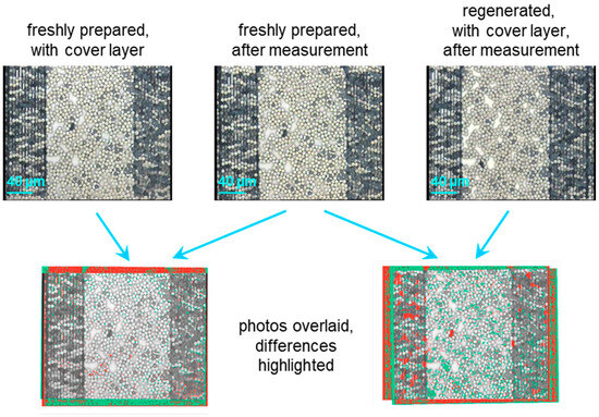
Figure 4.
Active part of a two-port SAW resonator device structured with 5 µm polystyrene particles and coated with a parylene C cover layer. The photos in the top row were taken after preparation and deposition of the first cover layer (left), after a protein adsorption experiment (middle), and after regeneration, including deposition of another cover layer, and an additional protein adsorption experiment (right). The images in the bottom row show overlays of the respective photos, with the differences highlighted in red and green.
As a first approximation, the photos in the top row of Figure 4 appear to be largely similar. Slight differences partly resulted from dust flakes, partly from variations in different conditions during the photographic documentation. The superimposed images demonstrate that the vast majority of the particles maintained their position after measurement in the flow cell, regardless of whether the structures were freshly prepared or regenerated. Therefore, the freshly applied parylene C cover layers held the particles in place on new or regenerated structures. Determining the actual layer composition and thickness before and after regeneration and measurement will be part of future investigations.
In a preliminary protein adsorption measurement, HSA was applied on SAW resonators structured with 20 µm particles, both freshly prepared and regenerated. The parylene C cover layer was activated with plasma, similar to the activation step applied for structuring (see Section 2.4). The results are shown in Figure 5.
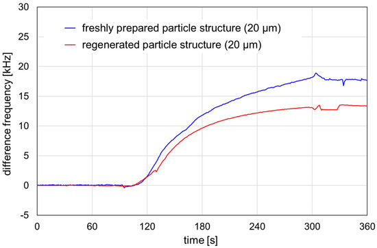
Figure 5.
Signal responses obtained by HSA adsorption on SAW resonators structured with 20 μm particles. The structures were freshly prepared (blue line) or regenerated (red line). Prior to the measurement, the parylene cover layer was activated with plasma, as described in Section 2.4. The HSA sample, 4 mg/mL, was injected into a PBS carrier stream. Injection interval: 60–300 s.
Both freshly prepared and regenerated SAW resonators structured with 20 µm particles showed a signal increase due to HSA adsorption on the activated parylene C. The difference frequency shifts were calculated as mean difference frequencies within the 320–350 s range after the injection interval. The difference frequency shift was 17.8 kHz for the freshly prepared resonator and 13.3 kHz for the regenerated resonator, representing 75% of the shift obtained for the freshly prepared resonator. Therefore, structured SAW resonators can be used for protein adsorption experiments after regeneration. The reproducibility of the results and the comparability of their signal responses with those of freshly prepared structured SAW resonators is still under investigation, as is their potential use as real biosensors with sensitive coatings.
4. Conclusions
Low-pressure plasma is suitable to regenerate microstructures on devices with IDEs or IDTs, as shown with SAW resonators structured with polystyrene particles. The structured SAW resonators exhibited analogous contact angles and resonance parameters, regardless of whether they were tested immediately after preparation or after regeneration following a bioanalytical measurement. Therefore, future bioanalytical experiments should not reveal significant differences between new and regenerated structured SAW resonators. This regeneration method can be applied to devices with sub-microstructures or nanostructures, as long as the plasma parameters are adjusted to preserve the integrity of the underlying structure. This would include a closer investigation of the structures and coatings before and after regeneration. After adjusting the regeneration parameters, investigating the repeatability of the regeneration process would be appropriate.
Supplementary Materials
The following supporting information can be downloaded at: https://www.mdpi.com/article/10.3390/coatings16030283/s1; Table S1: Measurement data for determining the contact angles of parylene C-coated SAW resonators that were unstructured or structured with 5 µm or 20 µm particles (n = 6). The structures were either freshly prepared or regenerated. The reading accuracy of the contact angle measurement microscope was 1°; Figure S1: Exemplary transmission spectra obtained with a vector network analyzer for a SAW resonator structured with 5 µm particles and coated with a 0.05 μm parylene C cover layer: (a) attenuation spectrum and (b) phase spectrum. The crosses and the dashed line label the S21 parameters, i.e., the maximum in the attenuation spectrum (a), the corresponding frequency (i.e., resonance frequency), and the corresponding phase (b); Table S2: Measurement data for determining the resonance parameters of SAW resonators structured with 5 μm particles (n = 4). The sensor numbers correspond to those in Table S1. The reading accuracies were whole Hertz for the resonance frequency and two decimal places for attenuation and phase.
Author Contributions
Conceptualization, K.L.; methodology, N.S., M.M., A.V. and K.L.; validation, N.S., M.M., A.P. and K.L.; formal analysis, N.S., M.M. and K.L.; investigation, N.S., M.M. and A.P.; resources, A.V. and K.L.; data curation, N.S., M.M. and K.L.; writing—original draft preparation, K.L.; writing—review and editing, K.L.; visualization, N.S. and K.L.; supervision, K.L. and A.V.; project administration, K.L. All authors have read and agreed to the published version of the manuscript.
Funding
This research received no external funding.
Institutional Review Board Statement
Not applicable.
Informed Consent Statement
Not applicable.
Data Availability Statement
The data presented in this study are included in the article/Supplementary Materials. Further inquiries can be directed to the corresponding author.
Conflicts of Interest
The authors declare no conflicts of interest.
References
- Bruzzone, A.A.G.; Costa, H.L.; Lonardo, P.M.; Lucca, D.A. Advances in engineered surfaces for functional performance. CIRP Ann. 2008, 57, 750–769. [Google Scholar] [CrossRef]
- Deka, M.; Sinha, N.; Das, R.; Hazarika, N.K.; Das, H.; Daurai, B.; Gogoi, M. A review on the surface modification of materials for 3D-printed diagnostic devices. Anal. Methods 2024, 16, 485–495. [Google Scholar] [CrossRef]
- Lingden, D.; Willis, P.; Bhattarai, J.K.; Stine, K.J. Nanoporous Gold Nanoparticles-Modified Electrode for the Detection of Endotoxins. Micromachines 2025, 16, 1014. [Google Scholar] [CrossRef] [PubMed]
- Tsuji, S.; Kawaguchi, H. Colored thin films prepared from hydrogel microspheres. Langmuir 2005, 21, 8439–8442. [Google Scholar] [CrossRef]
- Shinar, R.; Liu, G.J.; Porter, M.D. Graphite microparticles as coatings for quartz crystal microbalance-based gas sensors. Anal. Chem. 2000, 72, 5981–5987. [Google Scholar] [CrossRef] [PubMed]
- Bazin, G.; Zhu, X.X. Crystalline colloidal arrays from the self-assembly of polymer microspheres. Prog. Polym. Sci. 2013, 38, 406–419. [Google Scholar] [CrossRef]
- Zargartalebi, H.; Hejazi, S.H.; Sanati-Nezhad, A. Self-assembly of highly ordered micro- and nanoparticle deposits. Nat. Commun. 2022, 13, 3085. [Google Scholar] [CrossRef] [PubMed]
- Cui, L.Y.; Zhang, J.H.; Zhang, X.M.; Huang, L.; Wang, Z.H.; Li, Y.F.; Gao, H.N.; Zhu, S.J.; Wang, T.Q.; Yang, B. Suppression of the Coffee Ring Effect by Hydrosoluble Polymer Additives. ACS Appl. Mater. Interfaces 2012, 4, 2775–2780. [Google Scholar] [CrossRef]
- Cui, L.Y.; Yan, Y.; Zhao, X.Y.; Yu, C.L.; Ma, Y.; Yang, B. Controlling coffee ring structure on hydrophobic polymer surface by manipulating wettability with O2 plasma. Chin. Chem. Lett. 2017, 28, 1–5. [Google Scholar] [CrossRef]
- Yin, Y.D.; Lu, Y.; Gates, B.; Xia, Y.N. Template-assisted self-assembly: A practical route to complex aggregates of monodispersed colloids with well-defined sizes, shapes, and structures. J. Am. Chem. Soc. 2001, 123, 8718–8729. [Google Scholar] [CrossRef]
- Sun, J.N.; Yu, Y.M.; Tang, J.M.; Zeng, Y.; Chen, J.X. Plasma Cleaning Technology: Mechanisms, Influencing Factors, and Applications. IEEE Access 2025, 13, 37221–37242. [Google Scholar] [CrossRef]
- Alemán, C.; Fabregat, G.; Armelin, E.; Buendía, J.J.; Llorca, J. Plasma surface modification of polymers for sensor applications. J. Mater. Chem. B 2018, 6, 6515–6533. [Google Scholar] [CrossRef]
- Jeon, B.J.; Kim, M.H.; Pyun, J.C. Application of a functionalized parylene film as a linker layer of SPR biosensor. Sens. Actuators B Chem. 2011, 154, 89–95. [Google Scholar] [CrossRef]
- Zhang, H.; Lv, X.Q.; Huang, B.J.; Cheng, C.T.; Zhang, Z.; Zhang, Z.Y.; Fang, W.H.; Zhang, H.J.; Chen, R.; Huang, Y.L.; et al. In Situ Regeneration of Silicon Microring Biosensors Coated with Parylene C. Langmuir 2022, 38, 504–513. [Google Scholar] [CrossRef]
- Seo, Y.S.; Lee, H.W.; Kwon, H.C.; Choi, J.; Lee, S.M.; Woo, K.C.; Kim, K.T.; Lee, J.K. A study on characterization of atmospheric pressure plasma jets according to the driving frequency for biomedical applications. Thin Solid Films 2011, 519, 7071–7078. [Google Scholar] [CrossRef]
- Sun, T.; Blanchard, P.Y.; Mirkin, M.V. Cleaning Nanoelectrodes with Air Plasma. Anal. Chem. 2015, 87, 4092–4095. [Google Scholar] [CrossRef] [PubMed]
- Tintelott, M.; Schander, A.; Lang, W. Understanding Electrical Failure of Polyimide-Based Flexible Neural Implants: The Role of Thin Film Adhesion. Polymers 2022, 14, 3702. [Google Scholar] [CrossRef] [PubMed]
- Cheng, L.; Li, Z.Y.; Wang, J.R.; Xu, Z.; Liu, W.F.; Li, S.T. Degradation Behavior and Mechanism of Metalized Film Capacitor Under Ultrahigh Field. IEEE Trans. Dielectr. Electr. Insul. 2023, 30, 509–517. [Google Scholar] [CrossRef]
- Kumar, V.; Preeti, K.; Saini, V.; Kaushik, A.; Sharma, S.K. Interdigitated Electrodes (IDEs)-Supported Biosensing for Efficient Point-of-Care Applications. ECS Sens. Plus 2024, 3, 043401. [Google Scholar] [CrossRef]
- Munir, F.; Wathen, A.; Hunt, W.D. A new method for wideband characterization of resonator-based sensing platforms. Rev. Sci. Instrum. 2011, 82, 035119. [Google Scholar] [CrossRef]
- Hohmann, S.; Kögel, S.; Brunner, Y.; Schmieg, B.; Ewald, C.; Kirschhöfer, F.; Brenner-Weiss, G.; Länge, K. Surface Acoustic Wave (SAW) Resonators for Monitoring Conditioning Film Formation. Sensors 2015, 15, 11873–11888. [Google Scholar] [CrossRef]
- Mujahid, A.; Dickert, F.L. Surface Acoustic Wave (SAW) for Chemical Sensing Applications of Recognition Layers. Sensors 2017, 17, 2716. [Google Scholar] [CrossRef]
- Länge, K. Bulk and Surface Acoustic Wave Sensor Arrays for Multi-Analyte Detection: A Review. Sensors 2019, 19, 5382. [Google Scholar] [CrossRef]
- Kent, C.K.; Ramakrishnan, N.; Kesuma, H.P. Advancements in One-Port Surface Acoustic Wave (SAW) Resonators for Sensing Applications: A Review. IEEE Sens. J. 2024, 24, 17337–17352. [Google Scholar] [CrossRef]
- Ritter, F.; Hedrich, J.; Deck, M.; Ludwig, F.; Shakirov, D.; Rapp, B.E.; Länge, K. Polymer Structures on Surface Acoustic Wave Biosensors. Procedia Technol. 2017, 27, 35–36. [Google Scholar] [CrossRef]
- Relyon Plasma GmbH. Piezoelectric Direct Discharge Technology—PDD Technology®. Available online: https://www.relyon-plasma.com/technology/pdd/?lang=en (accessed on 8 January 2026).
- Harrick Plasma. Product Information. Available online: https://harrickplasma.com/wp-content/uploads/2022/01/Harrick-Plasma-Product-Information.pdf (accessed on 8 January 2026).
- Rapp, B.E.; Voigt, A.; Dirschka, M.; Länge, K. Deposition of ultrathin parylene C films in the range of 18 nm to 142 nm: Controlling the layer thickness and assessing the closeness of the deposited films. Thin Solid Films 2012, 520, 4884–4888. [Google Scholar] [CrossRef]
- Gholizadeh, S.; Lincoln, D.M.; Allahyari, Z.; Widom, L.P.; Carter, R.N.; Gaborski, T.R. Optimization of Parylene C and Parylene N thin films for use in cellular co-culture and tissue barrier models. Sci. Rep. 2023, 13, 4262. [Google Scholar] [CrossRef] [PubMed]
- Länge, K.; Blaess, G.; Voigt, A.; Götzen, R.; Rapp, M. Integration of a surface acoustic wave biosensor in a microfluidic polymer chip. Biosens. Bioelectron. 2006, 22, 227–232. [Google Scholar] [CrossRef] [PubMed]
- Rapp, B.E.; Voigt, A.; Dirschka, M.; Rapp, M.; Länge, K. Surface Acoustic Wave Resonator Chip Setup for the Elimination of Interfering Conductivity Responses. Micromachines 2024, 15, 501. [Google Scholar] [CrossRef]
- Meng, E.; Li, P.Y.; Tai, Y.C. Plasma removal of parylene c. J. Micromech. Microeng. 2008, 18, 045004. [Google Scholar] [CrossRef]
- Yuan, Y.; Lee, T.R. Contact Angle and Wetting Properties. In Surface Science Techniques; Bracco, G., Holst, B., Eds.; Springer: Berlin/Heidelberg, Germany, 2013; pp. 3–34. [Google Scholar]


Disclaimer/Publisher’s Note: The statements, opinions and data contained in all publications are solely those of the individual author(s) and contributor(s) and not of MDPI and/or the editor(s). MDPI and/or the editor(s) disclaim responsibility for any injury to people or property resulting from any ideas, methods, instructions or products referred to in the content. |
© 2026 by the authors. Licensee MDPI, Basel, Switzerland. This article is an open access article distributed under the terms and conditions of the Creative Commons Attribution (CC BY) license.