Abstract
This study systematically investigates the effect of hydrogen flow rate (100, 200, 300, and 400 sccm) on the properties of DC53 steel during a 4 h plasma nitriding process conducted at 400 °C in an asymmetric bipolar pulsed reactor. A comprehensive characterisation approach was employed. X-ray diffraction (XRD) was used to identify the phase composition, revealing the formation of a compound layer consisting of ε-Fe2–3N (identified by its (100), (101), and (102) planes) and γ’-Fe4N (identified by its (220) plane). Mechanical properties were assessed using Vickers microhardness for surface measurements and nanoindentation for depth profiling. Glow discharge optical emission spectroscopy (GD-OES) provided elemental depth analysis, while a ball-on-disk tribometer evaluated the tribological performance. The optimal treatment was achieved at a hydrogen flow rate of 200 sccm. This condition yielded a peak surface hardness of 1121.5 ± 69.2 HV0.2. GD-OES analysis directly correlated this mechanical enhancement to a high surface nitrogen content of approximately 8.5% and an effective diffusion depth of about 50 µm.
1. Introduction
Cold work tool steels are a cornerstone of modern manufacturing, valued for their exceptional hardness and wear resistance, which make them indispensable for high-stress applications such as cutting, stamping, and forming [1,2,3]. However, the performance and service life of these critical tools are determined not only by their bulk properties but are fundamentally limited by the integrity of their surface. Despite their inherent strength, these steels are often affected by surface-related failure mechanisms—including abrasion, fatigue, and corrosion—which can significantly reduce their operational efficiency and result in premature, costly tool failure [2,4,5].
To address these surface limitations, various surface engineering techniques have been developed to create a hard, resilient surface layer while maintaining a tough inner core [6,7,8,9]. Among these, thermochemical treatments such as nitriding are particularly important. However, conventional methods used for high-performance steels like DC53 present significant challenges. High-temperature gas nitriding can cause dimensional distortion, while salt bath nitriding, although efficient, relies on toxic cyanide salts, raising environmental and safety concerns [10]. This has driven the development of cleaner, more precise, and highly controllable surface modification technologies, with plasma nitriding emerging as a superior, environmentally friendly alternative [11,12].
In recent years, the application of plasma nitriding to cold work tool steels has been an active area of research. Studies on popular grades such as D2 (a close relative of DC53) and H13 have demonstrated significant improvements in surface hardness, wear resistance, and fatigue life [13,14,15]. Much of this research has focused on optimising process temperature and time to achieve sufficient diffusion depth without compromising the substrate’s tempered hardness [16,17]. For example, Pinedo and Monteiro [16] investigated the plasma nitriding of AISI 420 steel, highlighting the formation of a wear-resistant compound layer but also noting the risk of embrittlement from chromium nitride precipitation. Similarly, Adachi et al. [14] examined low-temperature nitriding of D2 and H13 steels to enhance wear performance while avoiding the formation of a brittle, continuous white layer.
While these studies confirm the viability of plasma nitriding, they also highlight the challenge of precisely controlling the resulting microstructure. The formation of the compound “white layer”—a hard but potentially brittle layer of iron and alloy nitrides—is a central issue. An excessively thick or brittle layer can cause spalling and a catastrophic loss of toughness [18,19,20,21,22]. The key to this control lies in the precise manipulation of the plasma chemistry, with the ratio of hydrogen-to-nitrogen (H2/N2) in the gas mixture being one of the most critical variables. Hydrogen is not merely a carrier gas; it plays an active role in surface cleaning by sputtering native oxides, controlling plasma density, and influencing the chemical pathways of nitride formation [23]. While the effect of the hydrogen-to-nitrogen ratio has been explored in austenitic stainless steels (to manage passivity) [24] and in lower-alloy steels, its specific, systematic influence on the phase composition (e.g., ε-Fe2–3N vs. γ-Fe4N) and resulting tribological properties of high-carbon, high-chromium cold work steels such as DC53 is not well documented.
This study systematically investigates the influence of the hydrogen-to-nitrogen ratio on the evolution of surface properties in DC53 tool steel during a low-temperature plasma nitriding process. By varying the hydrogen flow rate while keeping other parameters constant, we aim to establish a clear processing–structure–property relationship. This work provides a comprehensive analysis of the resulting microstructure, hardness, and tribological behaviour, offering insights into optimising the plasma nitriding process to enhance the durability and reliability of modern cold work tooling.
2. Materials and Methods
The substrate material used in this study was DC53 cold work tool steel, machined into specimens with a diameter of 24 mm and a thickness of 6.4 mm. The nominal chemical composition of the steel was approximately 1.0% C, 8.0% Cr, 2.0% Mo, 1.0% Si, 0.40% Mn, and trace amounts of V. Prior to surface treatment, the specimens were prepared by mechanical polishing. The surfaces were sequentially ground using silicon carbide (SiC) abrasive papers with grit sizes of 600, 800, 1000, 1200, and 1500, then polished with 3 µm and 1 µm aluminium oxide powders to achieve a mirror-like finish. Immediately after polishing, the samples underwent a two-step ultrasonic cleaning process, first in acetone and then in methanol, for 10 min each. The cleaned specimens were then dried with nitrogen gas before being promptly loaded into the plasma nitriding system.
The experiments were conducted in a custom-built plasma nitriding system, shown schematically in Figure 1. The system consisted of a vacuum chamber, an evacuation system, a cooling system, and a gas supply unit for high-purity argon (Ar, 99.995%), nitrogen (N2, 99.995%), and hydrogen (H2, 99.995%). An asymmetric bipolar pulse DC power supply (Advanced Energy Pinnacle® Plus+, Advanced Energy Industries, Inc., Denver, CO, USA) operating at a frequency of 50 kHz and a duty cycle of 20% was used to generate and sustain the plasma. The substrate holder served as the powered electrode and was equipped with a thermocouple for in situ temperature monitoring. The surface treatment was carried out in three sequential stages: plasma cleaning, preheating, and plasma nitriding. The initial plasma cleaning stage lasted 20 min to remove surface impurities and the native oxide layer. This was achieved using a mixture of Ar and H2 introduced at a flow rate of 500 sccm. Argon plasma promoted the physical removal of contaminants through ion bombardment (sputtering), while hydrogen plasma facilitated the chemical reduction of surface oxides. During this process, the working pressure was maintained at 0.25 Torr, resulting in a negative bias voltage of 625–800 V, a discharge current of 0.5–0.8 A, and a power of approximately 400 W. This concurrently raised the substrate temperature to 200 ± 10 °C in preparation for the next stage.
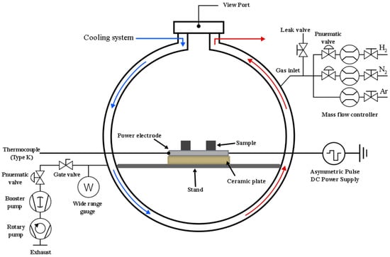
Figure 1.
Schematic diagram of the DC pulsed plasma nitriding system used in this study.
After the cleaning stage, the system was prepared for the main treatment. The preheating process began by increasing the operating pressure to approximately 2.0 Torr. This enabled the plasma current to be raised to 1.2 ± 0.1 A, enhancing the ion flux bombarding the substrate. To prevent thermal shock, the substrate temperature was gradually increased to the final treatment temperature over 20 min. The plasma nitriding process was then carried out for 240 min at a constant temperature of 400 °C using a reactive nitrogen-hydrogen (N2-H2) gas mixture. Nitrogen gas is essential for plasma nitriding, serving as the source of nitrogen atoms that harden the metal surface. In this work, the maximum nitrogen flow rate was set at 1000 sccm, based on the mass flow controller used (MKS instrument, Inc., GV50A013103GMV020, Andover, MA, USA). Hydrogen plays an important role in removing the oxide layer during the process. Therefore, the hydrogen-to-nitrogen ratio in the gas mixture is a key parameter for controlling the properties of the compound layer. Throughout this stage, the working pressure was maintained at 2.5 Torr. To investigate the effects of hydrogen concentration, the hydrogen flow rate was systematically varied, with values set at 100, 200, 300, and 400 sccm for different samples. After the treatment, the nitrided specimens were cooled to room temperature under vacuum within the chamber. A summary of all key process parameters is presented in Table 1.

Table 1.
Process parameters used for plasma cleaning, plasma preheating, and plasma nitriding.
The surface morphology of the untreated substrate and the plasma-nitrided samples was characterised using a scanning electron microscope (SNE-4500M, SEC Co., Ltd., Suwon, South Korea). All samples were observed in secondary electron (SE) emission mode, using an accelerating voltage of 20 kV. Representative micrographs were captured at a magnification of 5000× to analyse the fine-scale surface features. The crystallographic phase composition of the nitrided specimens was analysed using an X-ray diffractometer (XRD; D8 Advance, Bruker AXS GmbH, Karlsruhe, Germany) with a Cu Kα radiation source (λ = 1.5406 Å). Scans were performed over a 2θ angular range of 10° to 90°, with data collected at a step size of 0.03° and an integration time of 0.2 s per step. The thickness of the nitrided layer was examined on cross-sectioned samples using an optical microscope (OM). To determine the elemental composition as a function of depth, the DC53 sample was analysed by Glow Discharge Optical Emission Spectroscopy (GD-OES) using a Horiba GD Profiler HR instrument (HORIBA France SAS, Palaiseau, France). The system was operated with a radio-frequency (RF) generator set to 20 W under a constant argon pressure of 600 Pa. Prior to analysis, the plasma chamber was flushed for 30 s. The measurement sequence included a 5 s background acquisition and a 5 s pre-integration time. The final elemental depth profile was then acquired over a total duration of 2399.3 s.
Surface microhardness was measured using a Digital Display Low Load Vickers Hardness Tester (200HVS-5, Laizhou Huayin Testing Instrument Co., Ltd., Laizhou (Shandong Province), China). A standard Vickers diamond indenter was used to apply a load of 0.2 kgf (2 N) for a dwell time of 20 s. The final hardness value for each sample was reported as the average of five measurements taken at different locations. The friction and wear behaviour was investigated using a ball-on-disk tribometer (CSEM, Neuchâtel, Switzerland) under dry sliding conditions. An uncoated 6.00 mm SUS440C stainless steel ball was used as the counter-body, sliding against the prepared DC53 disk surfaces. Prior to testing, both surfaces were cleaned with acetone. The experiment was performed with a normal load of 2.00 N at a constant linear speed of 10.00 cm/s along a circular track with a radius of 5.00 mm. The test ran for a total of 10,000 laps, with data recorded at an acquisition rate of 3.0 Hz. All procedures were carried out in ambient air at a controlled temperature of 27.0 °C and a relative humidity of 15.00%. Following the wear tests, the morphology and dimensions of the wear tracks on the nitrided and non-nitrided samples were analysed using a 3D optical surface scanner (KEYENCE VK-X3000 Series, KEYENCE CORPORATION, Osaka, Japan) to determine the wear volume and mechanisms. The specific wear rate was calculated by dividing the volume loss by the normal load and the total sliding distance. Therefore, the standard unit for specific wear rate is cubic millimetres per Newton-metre.
3. Results and Discussion
3.1. Surface Morphology
Figure 2 shows photographs of the samples used for characterisation. In Figure 2a, the circular groove is the wear track of the DC53 tool steel (substrate) after ball-on-disk testing. The areas of the two central circles of the workpiece, shown in Figure 2b–e, are the sputtered regions of the nitrided samples after GD-OES measurement. The change in the DC53 tool steel samples from shiny metallic silver to matte grey is the expected result of the plasma nitriding process. This transformation is caused by two simultaneous effects. The first is a chemical change in the surface material, as the process supersaturates the surface with nitrogen, which then reacts with the iron (Fe) and alloying elements (such as chromium, Cr) in the steel at the top surface. This reaction forms a compound layer primarily composed of iron nitrides. These iron nitrides are ceramic compounds that absorb and reflect light differently from metals, giving them a characteristic dark grey or light grey appearance [13,14]. The second effect is a physical change in the surface texture, confirmed by the SEM images in Figure 3. The surface roughness of DC53 tool steel increases after plasma nitriding due to the bombardment of high-energy nitrogen ions accelerated into the steel surface. This process physically sputters atoms from the sample surface, acting like a microscopic sandblaster, etching the surface, increasing its microroughness, and scattering incoming light rays in many directions. The lighter-coloured edges (which appear closer to the original DC53 tool steel) are areas that were not nitrided effectively, as seen in Figure 1. The dark grey colour is the compound layer; therefore, the lighter colour indicates a less-developed compound layer. This non-uniformity is primarily caused by a non-uniform electric field. At sharp points, the electric field can concentrate, leading to overheating, excessive sputtering, and a thinner compound layer [25,26,27,28,29].
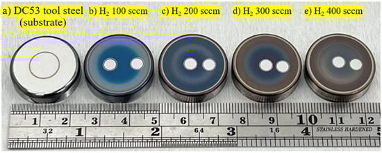
Figure 2.
Photograph of DC53 tool steel before and after plasma nitriding at different hydrogen flow rates (400 °C, 240 min).
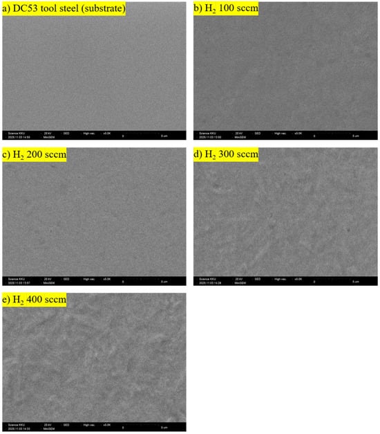
Figure 3.
SEM images of DC53 tool steel before and after plasma nitriding at different hydrogen flow rates (400 °C, 240 min).
3.2. X-Ray Diffraction
Figure 4 displays the X-ray diffraction (XRD) patterns of the DC53 steel samples before and after plasma nitriding at various hydrogen flow rates.
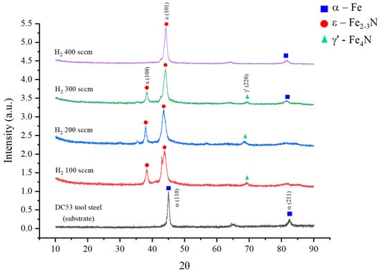
Figure 4.
X-ray diffraction pattern of DC53 tool steel after plasma nitriding for 240 min at different hydrogen contents.
As expected, the untreated control sample exhibits diffraction peaks corresponding solely to the body-centred cubic (BCC) α-Fe phase at 2θ angles of 45.2° and 82.6°, which is characteristic of the steel substrate [10,30,31,32,33,34]. Following plasma nitriding, a profound transformation of the surface metallurgy is observed. A key trend emerges where the hydrogen-to-nitrogen ratio critically governs the resulting phase composition. At lower hydrogen flow rates (H100 and H200), the patterns reveal the formation of a dual-phase compound layer consisting of both epsilon (ε-Fe2–3N) and gamma-prime (γ’-Fe4N) iron nitrides. The characteristic peaks for the ε phase were identified at approximately 38.0° and 43.9°, while the γ’ phase was detected near 69.4°. The dramatic reduction in the intensity of the underlying α-Fe peaks across all nitrided samples confirms the successful conversion of the surface into a nitride layer. Most notably, as the hydrogen flow rate increases, the relative intensity of the γ’-Fe4N phase diminishes. This trend culminates in the H400 sample, where the γ’ phase peaks are completely suppressed. The resulting diffractogram is dominated by a highly intense and sharp peak corresponding to the (101) plane of the ε-Fe2–3N phase. These results unequivocally demonstrate that the hydrogen flow rate is a powerful control parameter for selectively engineering the phase constituents of the nitrided layer, enabling a transition from a dual-phase (ε + γ’) structure to a predominantly single-phase ε-nitride surface.
3.3. Vicker Microhardness
Figure 5 illustrates the profound effect of hydrogen flow rate on the surface and bulk microhardness of the DC53 tool steel. The untreated control sample serves as a baseline, exhibiting a nominal hardness of 564.5 ± 28 HV0.2, with no significant variation between the surface and the bulk. Upon plasma nitriding, a substantial increase in surface hardness is achieved. The relationship between hydrogen flow rate and hardness follows a distinct parabolic trend, peaking at an optimal condition. A hydrogen flow rate of 100 sccm yielded a significant hardness of 968.5 ± 17.8 HV0.2. However, the maximum surface hardness, an impressive 1121.5 ± 69.2 HV0.2—nearly double that of the untreated steel—was achieved at a hydrogen flow rate of 200 sccm. This peak in hardness is directly attributed to the formation of a dense, well-developed compound layer rich in the hard ε-Fe2–3N phase, as was suggested by the XRD analysis.
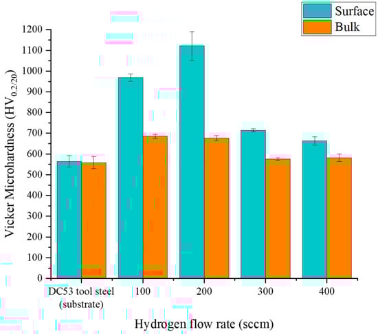
Figure 5.
Comparing surface and bulk hardnesses using Vicker microhardness test of DC53 tool steels after treatment with plasma nitriding at different hydrogen flow rates.
Beyond this optimum point, increasing the hydrogen flow rate to 300 and 400 sccm resulted in a progressive decrease in surface hardness to 714.4 ± 7.9 HV0.2 and 663.0 ± 19.4 HV0.2, respectively. This decline can be explained by two competing mechanisms. While hydrogen is essential for surface activation, an excessive amount can lead to a dilution effect, where a higher concentration of hydrogen in the plasma increases the probability of N + H recombination in the gas phase [35,36]. This reduces the flux of active nitrogen species available for diffusion into the steel surface, resulting in a thinner or less dense nitride layer and, consequently, lower hardness. These findings confirm that precise control over the hydrogen content is critical to maximising the strengthening effect of the plasma nitriding process.
3.4. OM Image and GD-OES
To quantify the depth and concentration of nitrogen penetration, the nitrided layers were analysed using GD-OES, with the results presented in Figure 6. The depth profiles clearly show that the hydrogen flow rate is a determining factor in the efficiency of nitrogen diffusion. The optimal case was observed at a hydrogen flow rate of 200 sccm (Figure 6b), which yielded the most desirable profile: a high surface nitrogen concentration of approximately 8% mass and the deepest effective case depth, with nitrogen penetrating well beyond 90 µm. This rich and deep nitrogen profile provides a direct explanation for the peak surface hardness observed in the same sample. Conversely, increasing the hydrogen flow rate to 400 sccm (Figure 6d) proved to be counterproductive. This condition resulted in the lowest nitrogen diffusion, with a shallow penetration depth of less than 10 µm and a surface concentration of only 2% mass. These results highlight the dual role of hydrogen in the plasma nitriding process. At an optimal concentration, hydrogen ions are beneficial, effectively removing the native oxide layer from the steel surface and opening pathways for nitrogen diffusion. However, an excessive hydrogen concentration leads to a detrimental side reaction in the plasma. The increased availability of hydrogen atoms promotes the formation of ammonia (NH3) through chemical reactions with active nitrogen species [37,38,39]. This newly formed ammonia gas is subsequently removed from the vacuum chamber by the pumping system, effectively depleting the plasma of the atomic nitrogen required for the nitriding process. Therefore, precise control of the hydrogen ratio is essential to prevent this parasitic reaction and ensure maximum nitrogen diffusion into the substrate.
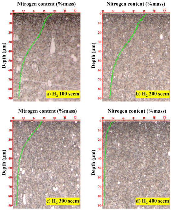
Figure 6.
Comparing the nitrogen concentration in the depth profile of the nitride samples obtained from the GD-OES technique: (a) H2 100 sccm, (b) H2 200 sccm, (c) H2 300 sccm and (d) H2 400 sccm.
3.5. Wear Test
As the samples with H2 100 sccm and 200 sccm exhibited significantly higher surface hardness and nitriding layer thickness than those with H2 300 sccm and 400 sccm, only the conditions with H2 100 sccm and 200 sccm were characterised. The results of the ball-on-disk wear tests, shown in the micrographs, provide a clear qualitative and quantitative assessment of the effect of plasma nitriding on the tribological performance of DC53 tool steel. A distinct transition in the dominant wear mechanism was observed between the untreated substrate and the nitrided samples. The wear track on the untreated substrate (Figure 7a) is characterised by severe surface damage. The micrograph reveals deep grooves, metallic debris, and significant plastic deformation. This morphology indicates abrasive wear, specifically a ploughing action by the counter-body or by detached hard wear debris [15]. This suggests that under high local pressure, microscopic cold-welding occurred between the sample and the counter-body, followed by tearing as the material was sheared. The red profilometer line, which displays large-amplitude, jagged peaks and valleys, quantitatively supports this finding, confirming deep material removal and high final surface roughness. The wear tracks on the plasma-nitrided samples, treated with both 100 sccm (Figure 7b) and 200 sccm (Figure 7c) of hydrogen, show a marked improvement in wear resistance. The most significant finding is the complete absence of deep grooves and adhesive wear features. The surface profilometer traces for both nitrided samples are exceptionally smooth and flat, confirming that the hard compound layer effectively resisted ploughing and abrasion [13]. The primary wear mechanism for the nitrided surfaces has clearly transitioned to mild oxidative wear. The distinct blue, purple, and gold colours visible within the tracks are not metallic debris; they are tribo-oxidation layers formed as a result of localised frictional heating [14]. These thin, protective oxide films (often Fe2O3 or Fe3O4) create the colours via thin-film interference. Their presence indicates a mild, stable wear regime where material is slowly and gently removed as a fine oxide powder, rather than being catastrophically torn from the surface [16].
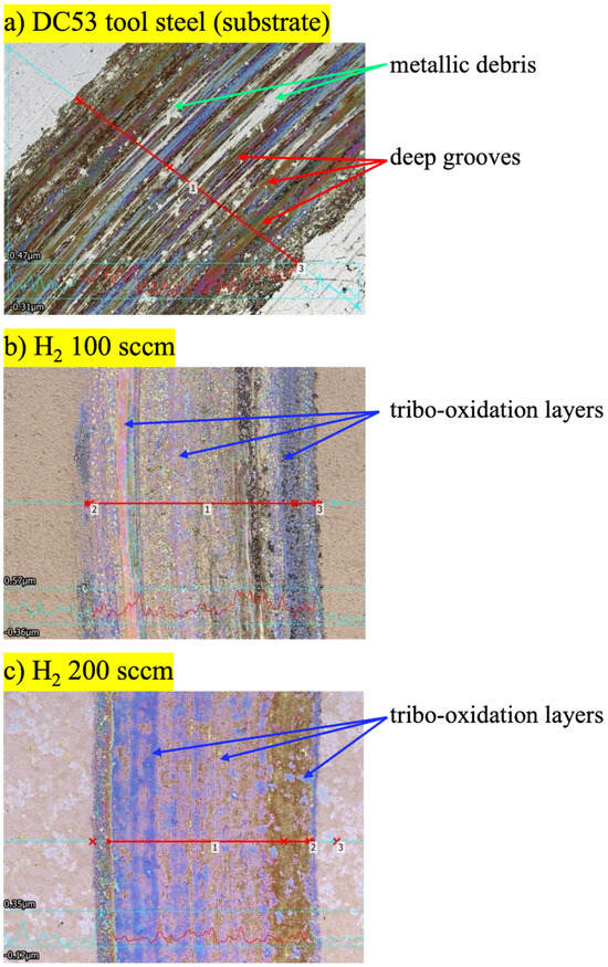
Figure 7.
Wear track of the DC53 tool steel before and after plasma nitriding with the hydrogen flow rate of 100 and 200 sccm.
The 2D cross-sectional profiles of the wear tracks provide definitive quantitative data to supplement the qualitative morphological analysis. These data confirm that plasma nitriding significantly enhances the wear resistance of DC53 tool steel and that the hydrogen flow rate is an important parameter in this improvement. The untreated DC53 substrate (Figure 8a) shows a substantial wear track area of 163.14 µm2 and a maximum depth of 0.78 µm. This corresponds to a volume loss of 5.12 × 10⁻³ mm3 and a specific wear rate of 8.16 × 10⁻⁶ mm3/N·m. The significant material loss is a direct result of dominant adhesive and abrasive wear mechanisms. As observed in the micrographs, the ductile but tough substrate is highly susceptible to ploughing, galling, and material tearing under load [13,15]. Both plasma nitriding treatments resulted in clear and substantial improvement in wear resistance. The sample treated with a hydrogen flow rate of 100 sccm (Figure 8b) showed a 39% reduction in wear volume (3.13 × 10⁻³ mm3), with a track area of 99.77 µm2 and a specific wear rate of 4.99 × 10⁻⁶ mm3/N·m. This demonstrates that the formation of a hard nitride compound layer was successful in partially resisting the severe wear mechanisms that affected the substrate [16]. The best improvement was achieved with the 200 sccm hydrogen flow rate (Figure 8c). The track profile is exceptionally shallow, with a maximum depth of just 0.09 µm. This sample exhibited a wear track area of only 13.13 µm2, which constitutes a 92% reduction in volume loss (4.24 × 10⁻⁴ mm3) and specific wear rate (6.57 × 10⁻⁷ mm3/N·m) compared to the untreated substrate and an 87% reduction compared to the 100 sccm sample. The very low wear volume and shallow profile are characteristic of a mild oxidative wear regime [14]. This indicates that the layer formed at 200 sccm possesses a good combination of high hardness (to resist abrasion) and sufficient toughness (to prevent brittle fracture and delamination). The wear process has been successfully transitioned from catastrophic adhesive and abrasive failure to stable, gradual oxidation and polishing [17]. These data strongly suggest that the hydrogen-to-nitrogen gas ratio is an important process parameter. The higher hydrogen flow (200 sccm) likely resulted in more suitable plasma chemistry, leading to a compound layer with a more favourable phase composition and mechanical integrity, thus providing the exceptional wear performance observed.
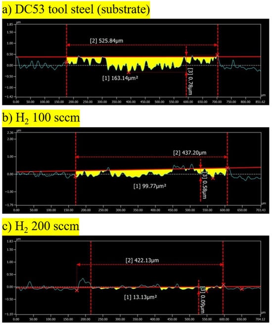
Figure 8.
Cross-sectional profile of the wear track of the DC53 tool steel before and after plasma nitriding with the hydrogen flow rate of 100 and 200 sccm.
Figure 9 shows the evolution of the coefficient of friction (CoF) as a function of sliding distance for the DC53 tool steel (substrate), H100, and H200 samples. The CoF data provide a dynamic, real-time explanation for the wear mechanisms and the quantitative material loss observed in the profilometer data. The relationship between the process parameters, frictional stability, and wear regime is not linear, as evidenced by the distinct behaviour of the three samples. The untreated DC53 control sample (black line) exhibits a high, relatively stable CoF. This behaviour is characteristic of a severe adhesive wear regime. The high frictional force is sustained by continuous stick-slip and galling mechanisms, where microscopic cold-welding is followed by the shearing and tearing of the ductile substrate [13,15]. The relative stability of the signal, punctuated by high-frequency noise, is typical of this continuous material transfer and ploughing, which directly results in the high specific wear rate (8.16 × 10⁻⁶ mm3/N·m) observed. The sample nitrided at 100 sccm H2 (red line) displays the highest average CoF and greater instability, characterised by large, chaotic fluctuations. This is not a stable wear process, indicating a brittle compound layer that is failing catastrophically [17]. Interestingly, while the frictional force is the highest, the total wear volume (99.77 µm2) was lower than that of the substrate. This suggests that although the process is unstable and high-friction, the rate of volumetric removal from this hard-but-brittle surface is still less than the large-scale material tearing of the soft, adhesive substrate. The sample treated with 200 sccm H2 (blue line) demonstrates the best tribological performance and the desired outcome of the surface treatment. It exhibits both the lowest average CoF and the highest stability. This result indicates that the layer formed under 200 sccm H2 conditions possesses the required combination of high hardness (to resist abrasion) and high toughness (to resist the brittle fracture seen in the 100 sccm sample). This tough layer promotes the formation of a stable, low-shear-strength tribo-oxidation layer on the surface [14,16,18,19,20]. This oxide film acts as a solid lubricant, effectively separating the two surfaces, preventing direct contact, and minimising both frictional force (CoF) and material loss. This finding correlates perfectly with the minimal wear area (13.13 µm2) measured by the profilometer, confirming a synergistic reduction in both friction and wear.
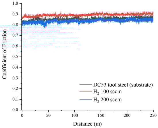
Figure 9.
Coefficient of friction of control and plasma nitriding samples at hydrogen flow rates of 100 and 200 sccm.
4. Conclusions
This study successfully investigated and demonstrated the critical influence of hydrogen flow rate on the microstructure, hardness, and tribological properties of DC53 tool steel during the plasma nitriding process. The hydrogen-to-nitrogen ratio is a decisive parameter in controlling the phase composition of the nitride layer. A hydrogen flow rate of 200 sccm was most effective in promoting the formation of a dense, uniform compound layer rich in the hard ε-Fe2–3N phase. In contrast, excessive hydrogen (400 sccm) was detrimental, hindering nitrogen diffusion, likely due to the parasitic formation of ammonia in the plasma. Consequently, the surface microhardness was significantly enhanced. The condition of 200 sccm hydrogen yielded a surface hardness of 1121.5 HV0.2, approximately double that of untreated DC53 tool steel. This hardness directly correlates with the formation of the nitride layer observed in the microstructural analysis. The tribological performance of the steel was also improved. A hydrogen flow rate of 200 sccm produced the best results among the investigated conditions, resulting in a 92% reduction in wear area compared to the untreated control sample. This improvement is attributed to the high surface hardness, low coefficient of friction, and the fundamental shift in the wear mechanism from severe adhesive and abrasive wear to a much milder polishing mechanism. This work establishes a clear processing–structure–property relationship, confirming that precise control of hydrogen content is a key strategy for engineering superior, high-performance surfaces on DC53 tool steel via plasma nitriding.
Author Contributions
Conceptualization, A.C.; Methodology, K.C. and T.F.; Formal analysis, A.C. and Y.O.; Investigation, K.C.; Writing—original draft, K.C.; Writing—review & editing, A.C. and Y.O.; Project administration, A.C. All authors have read and agreed to the published version of the manuscript.
Funding
This research was financially funded by Mahasarakham University (6719001/2567).
Institutional Review Board Statement
Not applicable.
Informed Consent Statement
Informed consent was obtained from all subjects involved in the study.
Data Availability Statement
The original contributions presented in this study are included in the article. Further inquiries can be directed to the corresponding author.
Conflicts of Interest
Author Toshiyuki Fukahori was employed by the company Nanotec Corporation. The remaining authors declare that the research was conducted in the absence of any commercial or financial relationships that could be construed as a potential conflict of interest.
Abbreviations
The following abbreviations are used in this manuscript:
| CoF | Coefficient of friction |
| OM | Optical image |
| GD-OES | Glow discharge optical emission spectroscopy |
References
- Theisen, W. Tools for processing materials. In Ferrous Materials; Berns, H., Theisen, W., Eds.; Springer: Berlin/Heidelberg, Germany, 2008; pp. 217–305. [Google Scholar] [CrossRef]
- Bae, K.; Moon, H.-S.; Park, Y.; Jo, I.; Lee, J. Influence of Tempering Temperature and Time on Microstructure and Mechanical Properties of Additively Manufactured H13 Tool Steel. Materials 2022, 15, 8329. [Google Scholar] [CrossRef] [PubMed]
- Krauss, G. Tool Steels. In Steels: Processing, Structure, and Performance, 2nd ed.; ASM International: Materials Park, OH, USA, 2015; pp. 621–645. [Google Scholar] [CrossRef]
- Medrea, C.; Fragkos-Livanios, L.; Giannakopoulos, K.I.; Statharas, D. Failure analysis of two cold-working cutting tools. MATEC Web Conf. 2018, 188, 04026. [Google Scholar] [CrossRef]
- Jarfors, A.E.W.; Castagne, S.J.; Danno, A.; Zhang, X. Tool Wear and Life Span Variations in Cold Forming Operations and Their Implications in Microforming. Technologies 2017, 5, 3. [Google Scholar] [CrossRef]
- Mittemeijer, E.J.; Somers, M.A.J. Thermodynamics, Kinetics and Process Control of Nitriding. Surf. Eng. 1997, 13, 483–497. [Google Scholar] [CrossRef]
- Suresh Gyan Vihar University. QPQ salt bath nitriding and its effect on steels: Review. J. Adv. Res. Mater. Sci. Technol. 2023, 9, 90–98. [Google Scholar]
- Oliveira, L.F.; Castro, V.V.; Vasconcellos, M.A.Z.; Neves, J.C.K.d.; Malfatti, C.d.F.; Rocha, A.d.S. Effects of gas mixture on active screen plasma nitriding and post-oxidation of a 4140 steel. Surf. Coat. Technol. 2024, 476, 130272. [Google Scholar] [CrossRef]
- Grigoriev, S.N. Technologies of Coatings and Surface Hardening: Industrial Applications. Coatings 2023, 13, 511. [Google Scholar] [CrossRef]
- Scheuer, C.J.; Zanetti, F.I.; Cardoso, R.P.; Brunatto, S.F. Influence of process temperature on phase formation in plasma nitrided AISI 420 steel. In Proceedings of the Brazilian Congress of Engineering and Materials Science (22. CBECIMAT), Natal, Brazil, 6–10 November 2016. [Google Scholar]
- Li, G.J.; Peng, Q.; Li, C.; Wang, Y.; Gao, J.; Chen, S.-Y.; Wang, J.; Shen, B.-L. Effect of DC plasma nitriding temperature on microstructure and dry-sliding wear properties of 316L stainless steel. Surf. Coat. Technol. 2008, 202, 2749–2754. [Google Scholar] [CrossRef]
- Aizawa, T.; Kuwahara, H. Plasma nitriding as an environmentally benign surface structuring process. Mater. Trans. 2003, 44, 1303–1310. [Google Scholar] [CrossRef]
- Mokrzycka, M.; Przybyło, A.; Góral, M.; Koscielniak, B.; Drajewicz, M.; Kubaszek, T.; Gancarczyk, K.; Gradzik, A.; Dychtoń, K.; Poręba, M.; et al. The Influence of Plasma Nitriding Process Conditions on the Microstructure of Coatings Obtained on the Substrate of Selected Tool Steels. Adv. Mech. Mater. Eng. 2024, 41, 5–16. [Google Scholar] [CrossRef]
- Adachi, S.; Egawa, M.; Yamaguchi, T.; Ueda, N. Low-Temperature Plasma Nitriding for Austenitic Stainless Steel Layers with Various Nickel Contents Fabricated via Direct Laser Metal Deposition. Coatings 2020, 10, 365. [Google Scholar] [CrossRef]
- Wen, D.C. Erosion and wear behavior of nitrocarburized DC53 tool steel. Wear 2010, 268, 629–636. [Google Scholar] [CrossRef]
- Pinedo, C.E.; Monteiro, W.A. On the Kinetics of Plasma Nitriding a Martensitic Stainless Steel Type AISI 420. Surf. Coat. Technol. 2004, 179, 119–123. [Google Scholar] [CrossRef]
- Ahangarani, S.; Sabour, A.R.; Mahboubi, F.; Shahrabi, T. The Influence of Active Screen Plasma Nitriding Parameters on Corrosion Behavior of a Low-Alloy Steel. J. Alloys Compd. 2009, 484, 222–229. [Google Scholar] [CrossRef]
- Olzon-Dionysio, M.; Campos, M.; Kapp, M.; de Souza, S.; de Souza, S.D. Influences of plasma nitriding edge effect on properties of 316 L stainless steel. Surf. Coat. Technol. 2010, 204, 3623–3628. [Google Scholar] [CrossRef]
- Kleinjohann, K.C.; Ramos, B.B.; Bernardelli, E.A.; Maliska, A.M. Characterization of AISI 316L Stainless Steel Pattern via DC Plasma Nitriding. Mater. Sci. Forum 2016, 869, 675–679. [Google Scholar] [CrossRef]
- Axinte, M.; Vizureanu, P.; Cimpoesu, N.; Nejeru, C.; Burduhos-Nergis, D.-P.; Epure, E.-L. Analysis of Physicochemical Properties of W1.8507 Steel Parts with Sharp Edges, Thermochemically Treated by Plasma Nitriding with and without Polarized Screens. Coatings 2023, 13, 177. [Google Scholar] [CrossRef]
- Nishimoto, A.; Matsukawa, T.; Nii, H. Effect of Screen Open Area on Active Screen Plasma Nitriding of Austenitic Stainless Steel. ISIJ Int. 2014, 54, 916–919. [Google Scholar] [CrossRef]
- Aghajani, H.; Behrangi, S. Plasma Nitriding of Steels; Springer: Cham, Switzerland, 2017. [Google Scholar] [CrossRef]
- Donkó, Z.; Zajičková, L.; Sugimoto, S.; Harumningtyas, A.A.; Hamaguchi, S. Modeling characterisation of a bipolar pulsed discharge. Plasma Sources Sci. Technol. 2020, 29, 104001. [Google Scholar] [CrossRef]
- Kaewnisai, S.; Chingsungnoen, A. Surface hardening of SKD61 steel using low-temperature plasma nitriding. J. Appl. Sci. 2021, 20, 277–292. [Google Scholar] [CrossRef]
- da Silveira, J.A.; das Neves, J.C.K.; de Oliveira, L.F.; da Silva Rocha, A. Influence of the Active Screen on the Embrittlement of a Plasma-Nitrided Edge. Mat. Res. 2024, 27, e20240096. [Google Scholar] [CrossRef]
- Zagonel, L.F.; Figueroa, C.A.; Droppa, R., Jr.; Alvarez, F. Influence of the process temperature on the steel microstructure and hardening in pulsed plasma nitriding. Surf. Coat. Technol. 2006, 201, 452–457. [Google Scholar] [CrossRef]
- Alves, C., Jr.; da Silva, E.F.; Martinelli, A.E. Effect of workpiece geometry on the uniformity of nitrided layers. Surf. Coat. Technol. 2001, 139, 1–5. [Google Scholar] [CrossRef]
- Díaz-Guillén, J.C.; Naeem, M.; Hdz-García, H.M.; Acevedo-Davila, J.L.; Díaz-Guillén, M.R.; Khan, M.A.; Iqbal, J.; Mtz-Enriquez, A.I. Duplex plasma treatment of AISI D2 tool steel by combining plasma nitriding (with and without white layer) and post-oxidation. Surf. Coat. Technol. 2020, 385, 125420. [Google Scholar] [CrossRef]
- Li, C.X.; Bell, T.; Dong, H. A study of active screen plasma nitriding. Surf. Eng. 2002, 18, 174–181. [Google Scholar] [CrossRef]
- Kim, K.-H.; Lee, W.-B.; Kim, T.-H.; Son, S.-W. Microstructure and Fracture Toughness of Nitrided D2 Steels Using Potential-Controlled Nitriding. Metals 2022, 12, 139. [Google Scholar] [CrossRef]
- Cullity, B.D.; Stock, S.R. Elements of X-Ray Diffraction, 3rd ed.; Pearson Education Limited: Harlow, UK, 2014. [Google Scholar]
- Waseda, Y.; Matsubara, E.; Shinoda, K. X-Ray Diffraction Crystallography: Introduction, Examples and Solved Problems; Springer: Berlin/Heidelberg, Germany, 2011. [Google Scholar] [CrossRef]
- Landgraf, P.; Bergelt, T.; Rymer, L.-M.; Kipp, C.; Grund, T.; Bräuer, G.; Lampke, T. Evolution of Microstructure and Hardness of the Nitrided Zone during Plasma Nitriding of High-Alloy Tool Steel. Metals 2022, 12, 866. [Google Scholar] [CrossRef]
- Wen, D.C. Influence of layer microstructure on the corrosion behavior of plasma nitrided cold work tool steel. J. Mater. Sci. 2010, 45, 1540–1546. [Google Scholar] [CrossRef]
- Conci, M.D.; Bozzi, A.C.; Franco, A.R., Jr. Effect of plasma nitriding potential on tribological behaviour of AISI D2 cold-worked tool steel. Wear 2014, 317, 188–193. [Google Scholar] [CrossRef]
- Karakan, M.; Alsaran, A.; Çelik, A. Effects of various gas mixtures on plasma nitriding behavior of AISI 5140 steel. Mater. Charact. 2002, 49, 241–246. [Google Scholar] [CrossRef]
- Timárová, Ľ.; Breznická, A.; Mikuš, P.; Ius, M. Increasing the Corrosion Resistance of Structural Steels Using Plasma Nitriding. Key Eng. Mater. 2025, 1016, 17–26. [Google Scholar] [CrossRef]
- Moskalioviene, T.; Galdikas, A. The Effect of Hydrogen on Plasma Nitriding of Austenitic Stainless Steel: Kinetic Modeling. Metall. Mater. Trans. A 2015, 46, 5588–5595. [Google Scholar] [CrossRef]
- Kumar, S.; Baldwin, M.J.; Fewell, M.P.; Haydon, S.C.; Short, K.T.; Collins, G.A.; Tendys, J. The Effect of Hydrogen on the Growth of the Nitrided Layer in r.f.-Plasma-Nitrided Austenitic Stainless Steel AISI 316. Surf. Coat. Technol. 2000, 123, 29–35. [Google Scholar] [CrossRef]
Disclaimer/Publisher’s Note: The statements, opinions and data contained in all publications are solely those of the individual author(s) and contributor(s) and not of MDPI and/or the editor(s). MDPI and/or the editor(s) disclaim responsibility for any injury to people or property resulting from any ideas, methods, instructions or products referred to in the content. |
© 2025 by the authors. Licensee MDPI, Basel, Switzerland. This article is an open access article distributed under the terms and conditions of the Creative Commons Attribution (CC BY) license (https://creativecommons.org/licenses/by/4.0/).