Abstract
In this study, a novel high-manganese steel (HMS) was borided at 850, 900 and 950 °C for 2, 4, and 6 h by the pack boriding process. Contrary to previous literature, borided HMS uncommonly exhibited saw-tooth morphology like low alloy steels, and manganese enhanced the boron diffusion. Another striking analysis is that the “egg-shell effect” did not occur. The present study demonstrated the silicon-rich zone for the first time in the literature by EDX mapping. Moreover, the formation mechanism of silicon-rich zones was explained and termed as “compact transfer of silicones (CTS)”. XRD analysis showed the existence of FeB, Fe2B, MnB and SiC phases. The boriding time and temperature increased the thickness of the boride layer from 31.41 μm to 117.65 µm. The hardness of the borided layer ranged from 1120 to 1915 HV0.05. The activation energy of borided HMS was found to be a very low result compared to high alloy steel investigated in the literature. The Daimler-Benz Rockwell-C adhesion test showed that adhesions of borided HMS surfaces are sufficient. The dry sliding wear tests showed that boriding treatment increased the wear resistance of untreated HMS by 5 times. The present study revealed that the boriding process extended the service life of HMS components.
1. Introduction
High manganese steel (HMS) has been used in automotive [1,2], mining [3,4], and defense industries [5], as well as in oil and slurry pipes [6]. In particular, HMS has been widely used in industrial applications such as steelmaking equipment, crusher jaws, impact hammers, hoppers, grinding mill liners, crawler treads for tractors, and in the manufacture of cement and clay products [3,4]. It is also advised to use for construction, heavy equipment, and military bulletproof tanks by steel manufacturers such as POSCO. Its wear-resistance, high formability, high toughness at low temperature, non-magnetism, and high strength causes an increasing interest of its use in these industries. HMS has these superior properties through transformations in its microstructure. HMS shows three different deformation mechanisms: TRIP (Transformation Induced Plasticity), TWIP (Twinning Induced Plasticity) and TRIP/TWIP. In the TRIP mechanism, retained austenite transforms to martensite under strain [7]. The TWIP mechanism exhibits twin formation (γ--γT’) under mechanical loads [8]. The TRIP/TWIP mechanism performs both deformation twinning and transformation of austenite to martensite during the deformation [9]. The roles of alloying elements are quite effective in the differences in the microstructure of HMS. One of the most important alloying elements affecting the microstructural transformation of HMS against impacts is silicon. Silicon content of more than 1% in steel prevents the formation of cementite and stabilizes austenite at room temperature [10]. Many steel manufacturers (such as POSCO) invest in the manufacturing of HMS seriously due to its superior mechanical properties. Therefore, HMS usage has increased in many industrial areas such as mining, construction equipment, and slurry transporting. However, a major problem of these industrial applications is the decrease of the lifetime of components because of wear. Under extreme conditions, HMS cannot provide adequate wear resistance by itself. To solve this problem, surface treatments have been commonly applied to protect equipment and ensure superior wear resistance under harsh conditions. Since boriding is an economical and effective surface treatment, it can be preferred for improving the wear properties of HMS.
Boriding is a thermo-chemical process applied to improve the surface properties of metals. The boriding is usually applied between 800 to 1050 °C over a period of 0.5 to 10 h [11]. Although the boriding is carried out in plasma, liquid and gas media, pack (solid) boriding is the most commonly used in industry due to its affordable and simple process compared with other boriding methods. Moreover, pack boriding does not need to use a complex machine system. As a result of the boriding process, single Fe2B phase or Fe2B and FeB phases (double layer) are formed together on the surfaces of steel. When FeB phase occurs, it is formed above the Fe2B phase. As mentioned above, the boriding process is used to enhance surface properties of metallic materials such as corrosion resistance [12,13], hardness [14,15], wear resistance [16,17,18], tribo-corrosion resistance [19,20], and radiation protection [21]. There are many studies in the literature focusing on improving the wear and corrosion resistance of steel. Gutierrez-Noda et al. carried out boriding on AISI M2 at 950 °C for 6 h and reported that the boriding process decreased the wear rate of the substrate [22]. Keddam et al. obtained that the plasma paste boriding process significantly increased the wear resistance of AISI 440C steel [23]. Cardenas et al. investigated tribological behaviors of D2 and H13 steels. They observed that the wear resistance of the borided steels was 13 times higher than that of the unborided substrate [24]. Günen et al. reported that boriding increased the corrosion resistance of the AISI 304 steel against the acid solution about by seven times according to the unborided sample [25]. Medvedovski reported that boriding was a unique surface treatment for corrosion and wear resistance of large, long, and complex shaped steels and ferrous alloy tubular components used at the refinery, for oil and gas processing, etc. [26]. Medvedosvki and Antonov evaluated the dry erosion and slurry erosion resistance of borided J55 and L80 that were widely used in mineral processing and oil production. They deduced that borided components and tubing used in mineral processing, downhole oil production conditions and various engineering applications could be successfully employed [27].
Novelty of the Work
In this paper, boriding of a novel HMS was investigated. If the wear resistance of HMS is further improved, it will have longer service life and wider applications in many industries. Since no study has been observed in the literature about tribological properties of borided HMS, this study focuses on investigating the wear behavior, adhesion properties and diffusion kinetic of borided HMS at different processing temperatures and holding times.
2. Materials and Methods
The HMS used in this study was melted in an induction furnace and cast as a slab. The cast slab was homogenized at 1100 °C for 6 h. The slab was subsequently air-cooled to room temperature. The slab was heated at 1100 °C for 30 min before hot rolling to 5 mm and cooled in air. The hot-rolled sheet was subsequently cold-rolled to 45% thickness reduction in 4 passes. The chemical composition of HMS is shown in Table 1.

Table 1.
Chemical composition (in wt%) of the HMS.
The samples were cut to dimensions of 30 × 15 mm. Samples were mechanically polished with SiC sandpaper up to 1500 grade. The boriding was carried out at 850, 900 and 950 °C for 2, 4, and 6 h using the pack boriding method in a conventional furnace. EKabor-II powders (90 wt% SiC, 5 wt% B4C, and 5 wt% KBF4) were used for boriding. After treatment, the box was cooled down in the furnace slowly. The microstructural analysis of the sample was conducted with a scanning electron microscope (SEM-TESCAN MAIA3 XMU). The operating parameters were carried out with acceleration voltage: 20 kV, detection: BSE, beam intensity: 16.00, scan step: 200 nm. The component of the boride layer was studied by employing energy dispersive X-ray spectrometry (EDX) microprobe within SEM. The presence of borides formed in the layers was confirmed using X-Ray diffraction (XRD-Rigaku Ultima IV diffractometer) using Cu Kα radiation, 30 kV, 20 mA (λCu = 0.1540 nm). The investigated angular range was between 3° and 90°, steps scan of 3° and counting time of 1 m. The thicknesses of boride layers were measured with SEM. The micro-hardness (Shimadzu HMV-G series) was measured from the surface to the center in a line with a Vickers indenter with a 50 gr load for 15 s. Table 2 shows the sample nomenclature. Additionally, the unborided sample was termed base metal (BM).
Table 2.
List of samples of borided HMS.
The adhesion of the boride layers was determined by Daimler-Benz Rockwell-C adhesion test. The Daimler-Benz Rockwell-C adhesion test (BMS 200 RB) is applied according to the VDI 3198 norm, as a destructive quality test for coated compounds [28].
Diffusion kinetics of borided HMS was calculated with:
where x is the depth of the boride layer (mm), t is the boriding time (s), and D is the growth rate constant depending on the boriding temperature [29]. The growth rate constant, D, can be expressed by an Arrhenius equation as follows:
where D0 is a constant, Q is the activation energy (J/mol), T is the absolute temperature in Kelvin and R is the universal gas constant (8.31434 J/mol K) [29].
x2 = D × t
D = D0 exp(−Q/RT)
The surface roughness of the boride layer was examined by a portable surface roughness tester (Mitutoyo SJ-410 series). At least three measurements were carried out to calculate the average roughness of the surfaces. The friction coefficient (COF) plots of all samples were obtained during the dry sliding wear tests.
The dry sliding wear test was studied on a rectilinear reciprocating wear tester (Turkyus POD&HT&WT). Wear tests were carried out to use 6 mm diameter WC (1917 HV hardness) counter material on a rectilinear reciprocating wear tester due to its high hardness. Figure 1 shows the schematic diagram of tribotest. The x axis indicates the wear track width, and the y axis defines the wear ball movement direction during the tribotest.
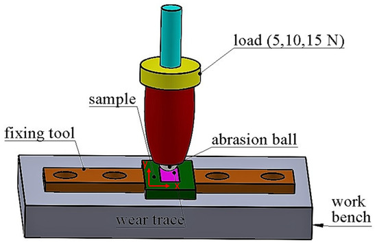
Figure 1.
Schematic diagram of tribotest.
The presence of wear debris at the sliding interface unidirectional motion like pin-on-disk can be found less than under reciprocating wear test condition due to centrifugal force. This force causes the removal of wear debris from the counter surface. Therefore, the reciprocating wear test circumstances will be more drastic than unidirectional motion like pin-on-disk [30]. HMS is generally used in mining, oil drilling and defense industries. According to some of the reasons mentioned above, the reciprocating wear test method displays more realistic results in the industrial usage of this steel. The wear tests were implemented under the load of 5, 10, and 15 N. Çimenoğlu et al. reported that no deformation was observed on Fe2B or Fe2B/FeB layers during the tests applied under lower loads (3 N load) because of Hertzian forces [16]. According to Gök et al. as the critical value of mechanical stress is exceeded, crack formation occurs more easily [17]. They carried out the wear test under 5 N and they observed delamination type wear mechanism at their samples, which is why the initial point of the wear test performed in the present study is 5 N load. Since the wear behavior of borided HMS was aimed to be observed under the different loads, the wear tests were applied under 5,10 and 15 N loads. The total sliding distances on the specimens were 200 m for each load. Each test was repeated three times for each load. The wear volume losses were obtained by post-test analysis of the wear scars measured using 3-D profilometry (HUVITZ HDS-5800). The wear rates were calculated according to:
R = V/l.d
R is the relative wear rate (mm3/Nm), V is the wear volume (mm3), l is the load (N), and d is the sliding distance(m).
3. Results and Discussions
3.1. Microstructural Characterization and XRD Analysis
FeB phase was not observed at 850 and 900 °C in Figure 2a,b; however, XRD results proved the presence of FeB at all boriding processes. FeB and Fe2B phases can be viewed obviously in Figure 3. Although HMS was high alloying steel (14% Mn and 2.75% Si), the saw-tooth borided morphology unexpectedly occurred on its surface. The saw-tooth structure commonly occurs at the borided low carbon and low-alloy steel [31,32,33]. In addition, Sinha reported that manganese flattened out the saw-tooth morphology in carbon steel and prevented the boron diffusion [32]. The flat boride morphology appears on the surface of high alloying steel [3,9,24], since the presence of alloying elements in grain boundaries blocks the diffusion of boron atoms from the surface to the inside of the high alloy steel [34,35]. Figure 3 exhibits that Mn is densely accumulated in the saw-tooth boron layer. Martini et al. explained that the saw-tooth boride layers were observed in steels because the iron borides prefer to grow in a crystallographic direction [001]. The iron borides contact neighbor crystals and grow inside the metal as an acicular (saw-tooth) shape. This layer grows in-depth, leading to a strong (002) preferred orientation [36]. This analysis may also be suitable for manganese borides. Ma et al. reported that MnB adopted an orthorhombic Pnma (space group) structure, isotropic with FeB [37]. Hence, the similarity of crystal structures of MnB and FeB can cause a saw-tooth morphology on borided HMS.
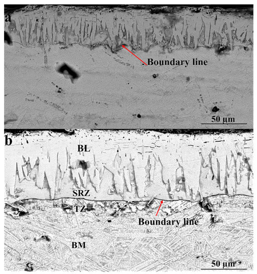
Figure 2.
Cross-section SEM microstructures of borided HMS samples: (a) 854, (b) 902.
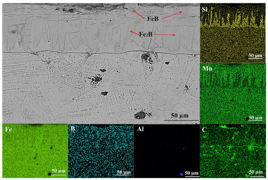
Figure 3.
EDX elemental mappings of borided HMS samples 952.
An evident boundary line that was not seen in many studies—particularly in studies exhibiting the saw-tooth morphology [16,31,38]—was also observed in Figure 2a,b and Figure 3. The boundary line separated the borided layer and transition zone. During boriding C and Si atoms diffuse away from the boride layer to the matrix and form boro-cementite (Fe3(B, C)) and iron-silico-borides as a separate layer under the Fe2B layer [32].
Several studies have found that the three regions are boride layer (BL), transition zone (TZ), and BM matrix in borided steel [17,29,39]. BM matrix was zone unaffected by heat or boron. TZ formed below the boundary line and was distinguished by the hardness different from that of the BM. Figure 3 also shows that there is a silicon-rich zone (SRZ) in the boride layer. Therefore, SRZ can be accepted as the fourth region of boride layer.
The most striking result to emerge from the data is shown in Figure 3. Since iron borides and manganese borides prevented the diffusion of Si from the metal core towards the surface of HMS, Si concentrated strongly between the borided layer (BL) and transition zone (TZ). Taktak [39] and Gök et al. [17] determined Si diffusion with the EDX line. In this study, SRZ was confirmed by the EDX mapping. SRZ is seen obviously in Figure 3 due to the high Si content of the HMS. As the borides formed, they push the Si atoms towards the steel core. Additionally, Si atoms in steel move towards the surface with increasing temperature. Si atoms cannot reach the surface because Taktak [39] reported that Si could not soluble in iron borides, concentrating effectively at the interface of steel. Si atoms accumulate between BL and TZ and SRZ occurs. Since this formation was not given any name in the literature, it was termed “compact transfer of silicones (CTS)”.
The SEM micrograph of sample 904 and its EDX point analyses are shown in Figure 4 and Table 3, respectively. The significant data in Table 3 revealed that Si and Al could not dissolve in iron borides and MnB. Al and Si ratios increased in SRZ due to their insolubility or solubility limits in the boron layer. The differences between BL and SRZ, where neither B nor Si was detected, respectively, are highlighted in Table 3. Moreover, it was determined that aluminum presence in SRZ has increased compared to BL and TZ. Although Al and B form intermetallics, such as AlB2 and AlB12, they are not observed as they are unstable at room temperature [40].
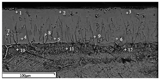
Figure 4.
EDX point analyses of SEM micrograph of sample 904.
Table 3.
Results of EDX point analyses of sample 904, wt%. (BL: borided layer; SRZ: silicon-rich zone; TZ: transition zone).
Figure 5 shows that the presence of Fe2B (JCPDS 00-003-1053), FeB (JCPDS 00-002-0869), SiC (JCPDS 00-002-1042), and MnB (JCPDS 03-065-5149) phases are detected in XRD analysis. Although FeB was not seen in SEM micrographs (Figure 2a,b), XRD results revealed its presence. XRD analysis revealed that the predominant phases were FeB and Fe2B. The aforementioned MnB adopted an isotropic orthorhombic Pnma structure with FeB [37]. This situation was discovered in Figure 3. Since Mn formed borides with a lattice constant similar to that of iron borides, it tended to dissolve in Fe2B and FeB phases. SiC can be formed during boriding due to the high level of Si in HMS.
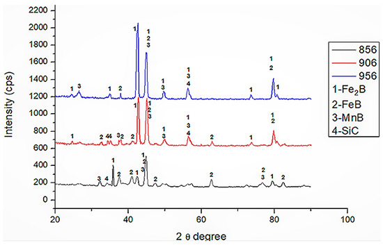
Figure 5.
XRD patterns of samples 856, 906 and 956.
3.2. Thicknesses of Boride Layers and Microhardness
Figure 6 shows that the thicknesses of boride layers range from 31.41 to 117.65 µm depending on treatment temperature and time. Minimum and maximum boride layer thicknesses were observed at samples 852 and 956, respectively. The thickness measurements indicated that the thickness of the boride layer increased with increasing process time and temperature. The comparison of boride layer thicknesses of different steels between this study and the other studies in the literature is shown in Table 4. It shows that HMS has the second-highest borided layer thickness in high alloy steel. Although Sinha reported that manganese reduced the boride layer thickness in carbon steel [32], the thickness measurements show that Mn facilitates boron diffusion in HMS.
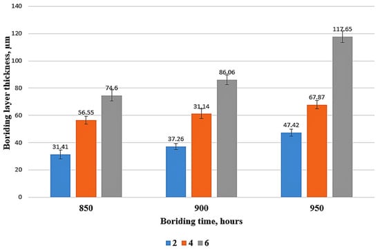
Figure 6.
Boride layers thicknesses.
Table 4.
The comparison of boride layer thicknesses between literature and in this study.
Figure 7 exhibits the cross-sectional microhardness measurement profile of borided HMS samples. The hardness of unborided HMS was 532 HV0.05. The highest hardness value was seen at 902 (1915 HV0.05). The hardness of the boride layers is approximately three to four times higher than that of the BM matrix due to the presence of FeB, Fe2B, and MnB phases which are significant for increasing the hardness of the surface. In the studies of Gök et al. [17] and Kayali [29], the high Cr content in steel caused chromium borides formation, which are harder than manganese borides, to reach hardness values of boride layer above 2000 HV. On the other hand, Duran et al., who boronized Inconel 718, was able to reach almost 1300 HV boron layer hardness due to the lower hardness of nickel borides than manganese borides [14]. Compared with unborided HMS, the hardness of the BM matrix in borided steel decreases with the effect of time and high temperature. However, in the literature, there is a common ratio between hardness and boriding time and temperature increases [17,29,31,41], which was not observed in this study. The changing distribution of various phases (MnB, FeB, Fe2B) in the boride layer can cause fluctuations in the hardness plot.
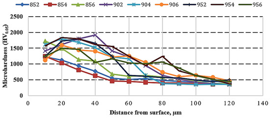
Figure 7.
Hardness profile of borided HMS.
3.3. Diffusion Kinetics
Process temperature and time are kinetic parameters of boriding treatment, and they are significant for controlling boriding treatment [42]. If the activation energy is low, diffusion will occur easily. Figure 8 exhibits a linear relationship between ln D and 1/T. The calculated value of activation energy for the boriding process in the HMS is 198.486 kJ/mol. Table 5 shows that Q calculated in the present study was compared with the results detected in the literature. Activation energy values increased in high alloy steel due to the presence of alloying elements in grain boundaries that block the diffusion of boron atoms from the surface to the inside of the steel [34,35]. Since the steels used in references [44] and [45] are low alloy steel, their activation energies have lower values than the HMS used in this study. However, it was observed that the activation energy of HMS was lower than other high alloy steels according to Table 5. The relevance of Mn that enhances the boron diffusion is supported obviously by the current diffusion kinetic results in Table 5.
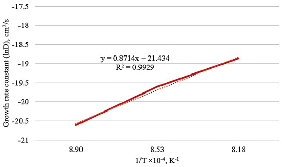
Figure 8.
Growth rate constant (lnD) versus 1/T of borided HMS.
Table 5.
The comparison of the boron activation energy (Q) of HMS with other steels in the literature.
3.4. Rockwell-C Adhesion Properties
Rockwell-C indentation was applied to analyze the adhesion properties of boride layers on HMS. The test is simple, low cost and can be suitable to identify the failures of borided layers. VDI 3198 Rockwell-C indentation test was carried out to cause damage on the borided layer under 1471 N load. The damage to the boride layer was compared with the quality map in [28]. The indentation craters of borided HMS formed after the adhesion test were evaluated by using SEM. The adhesion strength quality HF1–HF4 defines strong interfacial, whereas HF5 and HF6 define poor interfacial adhesion between the coating and the substrate [28]. Applied load and the contact geometry cause shear stresses at the interface. Suitable coatings manage to resist these stresses and prevent extended circular delamination, however, extended delamination at the crater around specifies a poor interfacial adhesion [28,46,47]. Three indentations were deployed for each specimen and intended surfaces were evaluated by SEM.
In conventional steels containing more than 0.8% Si, Si generates a very soft ferrite zone between the base material and the boron layer during boriding. At higher surface pressure, a quite brittle and hard boride layer is significantly damaged softer intermediate layer due to its penetration. Therefore, Si reduces the wear resistance of boride layers. The case is called the egg-shell effect [32,33]. However, Si affects to refine ε-martensite plates in HMS [48]. Since ε- martensite was a harder phase than ferrite, no egg-shell effect was detected in borided HMS in this study. Related results are shown in Figure 9.
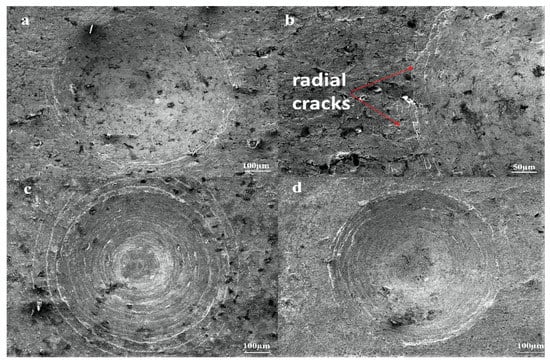
Figure 9.
SEM micrographs of VDI 3198 adhesion test on borided HMS: (a,b) 852, (c) 904, (d) 956.
Figure 9 shows that there are radial cracks at the circumference of indentation craters without any flaking or delamination on surfaces of borided HMS. The adhesion strength quality of surfaces of all samples used in this study match with HF1 and HF2. The VDI 3198 indentation test shows that there are strong interfacial bonds between the borided surface and HMS. Zong et al. [41], Taktak and Tasgetiren [46] observed HF5-HF6 adhesion quality at 1000 and 950 °C, respectively. Additionally, Zong et al. determined HF4-HF5 adhesion quality at 950 °C [41]. Both studies attribute that FeB is more prone to cracking and spalling due to tensile residual stresses under mechanical strain than Fe2B. However, in both studies, high chromium steels were used, and we think that hard, brittle chrome borides would have caused these adhesion damages, since in this study no delamination was observed on the surface as a result of the adhesion test, despite the boriding process at 950 °C for 6 h. The high content of MnB in boronized HMS, which has less hardness than chromium borides [37], may have caused this result.
3.5. Roughness, COF and Reciprocating Dry Sliding Wear Tests
Figure 10a–c demonstrate COF plots recorded during the wear tests of all samples, that were carried out under 5, 10, and 15 N loads, respectively. Moreover, Table 6 shows the mean value of COF results of all samples. The COFs of the BM were lower than those of the borided samples at all three test loadings. Although the COFs of sample 954 were lower than BM under the load of 5 and 10 N, the BM had lower COF than sample 954 under the load of 15 N. The COF can be affected by many parameters, such as the adhesion strength of the coating, hardness, roughness and distribution of phases occurred on the substrate surface [35]. Svahn et al. found that rougher surfaces have higher COF [49]. The low surface hardness of the substrate can cause low COF [20,50]. Costa-Aichholz et al. [20] reported that in the low hardness unborided sample, when in contact with the counter material plastic deformation occurs; being these deformations a result of ease to shear surface that leads to a low COF, according to the borided sample. Peaks show very high COF for borided morphology due to the high roughness of borided samples (902, 854, 956 in Figure 10a–c, respectively) in Figure 10. This could be owing to sharp asperities causing abrasive behavior leading to infrequent high COF [51]. This situation causes three-body wear between the sliding surfaces.
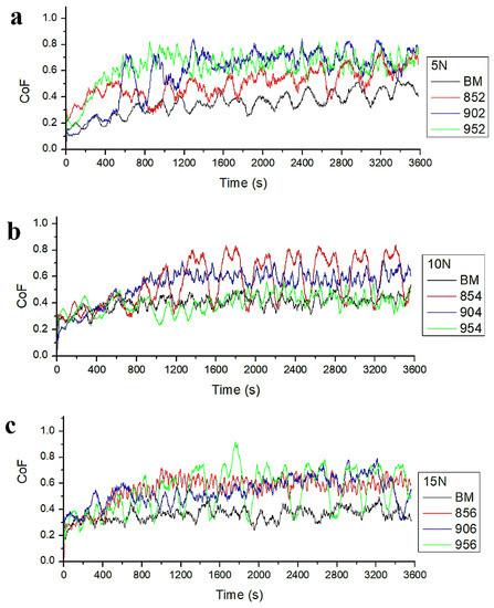
Figure 10.
COF curves of samples: (a) 5 N, (b) 10 N, (c) 15 N.
Table 6.
Average roughness and COF of samples (COF: coefficient of friction, St.D.: Standard Deviation).
Table 6 shows that the COF of the BM is lower than that of all borided samples. The surface roughness may have affected the COF results. The effect of high roughness is to distribute the load over asperities contact leading to higher frictional resistance and so a higher value of the COF can be obtained.
The volumetric wear results from dry sliding wear tests are shown in Figure 11. It exhibits that an increase in the applied load increases the volumetric wear losses of all samples. All borided samples performed lower volumetric wear loss than BM for each wear condition. The lowest volumetric wear losses were observed at sample 954 under the load of 5 and 10 N and sample 856 under the load of 15 N. Under 15 N load, sample 954 exhibited the second lowest volumetric wear loss. According to the literature, as boriding temperature and time increase, volumetric wear loss occurs [17,35]. This interpretation was related to the thickness and hardness of the boride layers obtained. In this study, a steady volumetric wear loss was not seen from tribological results of borided samples depending on the time and temperature increase. There are many parameters of material loss from the contacting surfaces under the loading such as work hardening tendency, applied load, type of relative movement, sliding speed, interfacial contact properties, and test environment, determining the contact stresses at the interface and material properties [30]. Each parameter might have caused this unsteady volumetric wear loss due to the complex morphology formed on the surface. In addition, reciprocating wear tests can affect the results of wear volume loss because of presences of wear debris at the sliding interface. Therefore, asperities might lead to different wear losses on the surfaces of each borided sample.
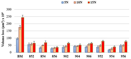
Figure 11.
Wear volume loss of samples.
The wear rates of samples are shown in Figure 12. The lowest wear rate was obtained in 954, 954, 856 under the load of 5, 10 and 15 N, respectively. The highest wear rates were observed at BM for each load. The hardness of the boride layer is significant for the improvement of wear resistance [52]. Due to the hardness of the FeB, Fe2B, and MnB phases, borided HMS showed more resistance to wear. The wear rate of the borided steels is more than six times lower than BM under 15 N load. Both wear rate and wear volume loss test results show that the boriding process significantly increases the wear resistance of HMS.
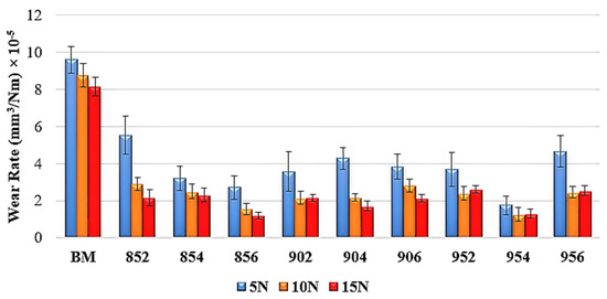
Figure 12.
Wear rates of samples.
EDS analyses were carried out on the worn area after the dry sliding wear test. The results of EDS line and mapping analyses aimed at determining the changes in the amount of existing elements on the surface of borided samples and BM after the dry sliding wear tests. Figure 13a,b shows EDX line analyses of samples 854 and BM, respectively. The x axis indicates the wear track width, and the y axis defines the wear ball movement direction during the tribotest. Figure 13a shows that the amount of Mn, S, Si, and K significantly decreased after the wear test. K arose due to KBF4 in the boriding powder. B decreased after the wear test, but it was not as much as the elements mentioned above. There was no significant decrease in iron, however, a significant increase in oxygen along the line indicates that oxide compounds are formed there. It is seen that the regions where oxygen elements increase are in dark color in Figure 13b. The quantification results indicate the decrease in iron and the increase in oxygen in these dark regions. Most likely, iron oxide occurred on the surface after the wear test. Figure 13b shows that except Al, C, and Si, no significant decrease in other elements actualized.
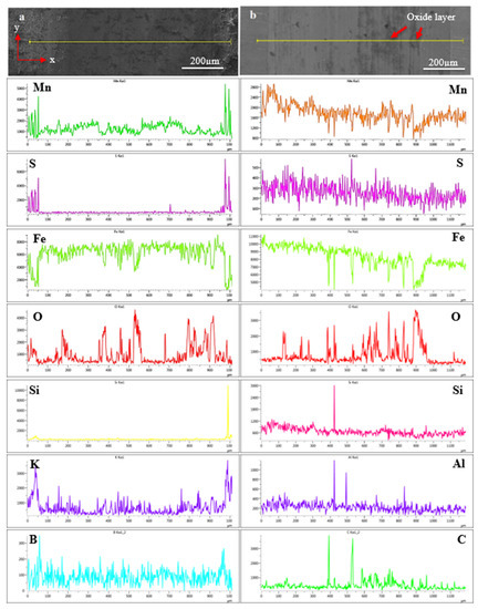
Figure 13.
EDX line analyses of borided HMS: (a) 854-15 N, (b) BM-15 N.
The most striking result to emerge from the data is that changes in Mn and S are noticed when comparing Figure 13a,b. Figure 13a shows that Mn and S significantly decreased after the wear test. It was determined that the amount of both elements—especially S—in the scale on the left side in the elemental analysis, increased significantly in the boriding process. As a result of the wear test in Figure 13b, a strong relationship between Mn and S does not appear in Figure 13a. MnS has a very low hardness, like 142 Vickers [53]. Therefore, Mn and S could decrease rapidly on the surface of borided HMS after the wear test. MnS formation may have adversely affected the wear volume results of the boronized layer because of its low hardness. However, it is not considered to be overly effective on wear resistance of borided HMS.
Figure 14 shows the cross-sectional view near the surface of HMS before the boriding process. MnS formation was not observed in Figure 14. EDS mapping analysis confirms the absence of MnS formation on the surface of HMS in SEM image.
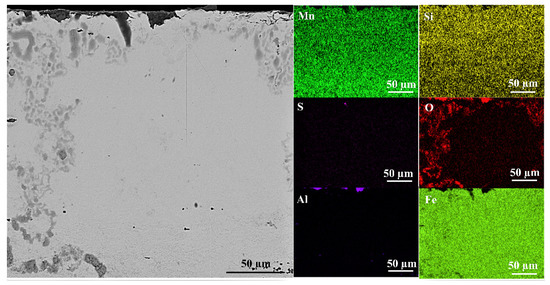
Figure 14.
Cross-sectional SEM view and EDS mapping analysis of unborided HMS.
Figure 15 provides additional evidence concerning MnS formation on the surface of HMS during boriding. The structures circled in Figure 15 are assumed to be MnS, probably formed by the effect of high temperature and low cooling kinetic that encourage its nucleation and growth during boriding.
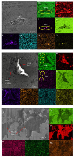
Figure 15.
EDX local mapping after the wear test: (a) 954 under 10 N load, (b) 906 under 5 N load, (c) BM under 5 N load.
Due to boriding powder, K was detected in the EDS mapping analysis of borided sample surface in Figure 15a,b. In Figure 15b, it is determined that oxides are formed like a shell. When oxide shells were broken due to the worn ball, K filled in these spaces (Figure 15a,b). As mentioned above, it is most likely that K stuck to the WC ball and filled these gaps by the movement of the ball. Figure 15c confirms the oxidation layer analysis performed in Figure 13b. The oxide layers are seen in dark color. Penetration of carbon atoms on the edge of the oxide layer is shown in Figure 15c.
The surface morphologies of the worn samples are given in Figure 16. It is seen that the oxide layer (dark region) partially delaminates under repeated loads because of plastic deformations in Figure 16a. Micro-cracks also occurred on the oxide layer. In the wear test, it is observed that the oxide layers formed on the surface disappeared with the increase of the applied load in Figure 16b. The debris and grooves occurred on the surface of BM. Almost the entire surface of borided HMS had smooth wear tracks. Micro-cracks on the oxide layer and pits on the borided surface as a consequence of surface fatigue [50] can be observed in Figure 16c,d. Figure 16d shows that particle impact-induced brittle fracture caused spalling off of the oxide layer. Oxidative type local delamination was observed in borided HMS. The oxide layer is spalled off in an area much larger than the impact crater, while the substrate is almost unaffected [54].
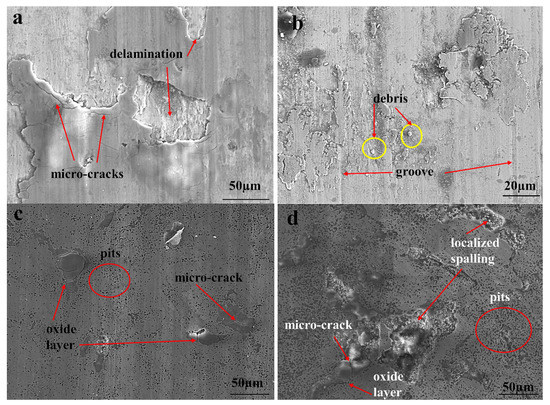
Figure 16.
SEM micrographs of the worn surfaces: (a) BM under 10 N, (b) BM under 5 N, (c) 854 under 15 N and (d) 956 under 10 N load.
4. Conclusions
- Fe2B, FeB, MnB, and SiC phases were determined on the surfaces of borided HMS. Although FeB was not observed at 850 and 900 °C in SEM micrographs, XRD results proved that FeB existed. One of the stunning results was that saw-tooth morphology was unexpectedly observed at the surface of borided HMS. SRZ was detected by using EDX mapping and the formation of SRZ was named as the compact transfer of silicones (CTS). The thicknesses of the boride layers on the surface of HMS range from 31.41 to 117.65 µm, depending on boriding temperature and time. The thickness results show that Mn enhanced the boron diffusion in steel. Diffusion kinetic results support this analysis. The hardness also increases with the new phases formed. According to the Daimler-Benz adhesion test, the adhesion quality of all borided HMS is acceptable (HF1 and HF2). Contrary to previous studies, high silicon content did not cause the “egg-shell effect”. It was also detected that MnS formed on the surface of HMS during boriding.
- The COF and roughness value of the BM were lower than borided HMS. A small number of wear damages were observed, such as oxide layer delamination, micro-cracks and surface fatigue causing pits to occur on the surface of the borided HMS. Delamination, micro-cracks, wear debris, and groove was detected on the surface of BM. The results of this study indicate that boriding allows a longer service life and increases the wear resistance of HMS. All borided HMS showed lower wear and rate higher wear resistance for all wear test conditions than BM. Therefore, the boriding process extends the service life of HMS components which are used in oil drilling, mining processes, defense and various other industries.
Author Contributions
Writing, supervisor, review and editing, F.H.; conceptualization, investigation, experimental work, writing, C.T.S. All authors gave final approval and agree to be accountable for all aspects of the work. All authors have read and agreed to the published version of the manuscript.
Funding
This study was supported by the Scientific Research Projects Coordination Unit of Karabük University (Project number: FDK-2020-2114). The authors would like to thank Mehmet Ali Taştan.
Institutional Review Board Statement
Not applicable.
Informed Consent Statement
Not applicable.
Data Availability Statement
Not applicable.
Conflicts of Interest
The authors declare no conflict of interest.
References
- Ren, T.; Shi, W.; Liu, R.; Lin, L.; Yang, H.; Li, L.; Shahzad, B. Effect of dew point on hot-dip galvanizing behavior of a high-manganese TWIP steel for automotive application. J. Iron Steel Res. Int. 2020, 27, 1200–1211. [Google Scholar] [CrossRef]
- Jin, X.; Zhong, Y.; Wang, L.; Wang, H. Effect of annealing temperature on the surface and subsurface microstructure of Al-added TWIP steel. Surf. Coat. Technol. 2020, 386, 125479. [Google Scholar] [CrossRef]
- Surzhenkov, A.; Goljandin, D.; Traksmaa, R.; Viljus, M.; Talviste, K.; Aruniit, A.; Latokartano, J.; Kulu, P. High Temperature Erosion Wear of Cermet Particles Reinforced Self-Fluxing Alloy HVOF Sprayed Coatings. Mater. Sci. 2015, 21, 386–390. [Google Scholar] [CrossRef] [Green Version]
- Wen, Y.H.; Peng, H.B.; Si, H.T.; Xiong, R.L.; Raabe, D. A novel high manganese austenitic steel with higher work hardeningcapacity and much lower impact deformation than Hadfield manganese steel. Mater. Des. 2014, 55, 798–804. [Google Scholar] [CrossRef]
- The Science of Armour Materials. In Armour Steels; Woodhead Publishing: Sawston, UK, 2017; pp. 55–115.
- Yue, X.; Wasson, A.J.; Anderson, T.D.; Ma, N.; Fairchild, D.P.; Jin, H. Welding Technology Development for an Erosion-Resistant Slurry Pipeline Steel: An investigation into the welding technology enabling the deployment of an erosion-resistant pipeline steel in the oil sands mining industry to achieve significant cost savings. Weld. J. 2018, 97, 229–242. [Google Scholar]
- Elliott, R.; Coley, K.; Mostaghel, S.; Barati, M. Review of Manganese Processing for Production of TRIP/TWIP Steels, Part 1: Current Practice and Processing Fundamentals. J. Miner. Met. Mater. Soc. 2018, 70, 680–690. [Google Scholar] [CrossRef]
- Frommeyer, G.; Brüx, U.; Neumann, P. Supra-Ductile and High-Strength Manganese-TRIP/TWIP Steels for High Energy Absorption Purpose. ISIJ Int. 2003, 43, 438–446. [Google Scholar] [CrossRef] [Green Version]
- Benzing, J.T.; Poling, W.A.; Pierceb, D.T.; Bentley, J.; Findley, K.O.; Raabe, D.; Wittig, J.E. Effects of strain rate on mechanical properties and deformation behavior of an austenitic Fe-25Mn-3Al-3Si TWIP-TRIP steel. Mater. Sci. Eng. A 2018, 711, 78–92. [Google Scholar] [CrossRef]
- Franceschi, M.; Pezzato, L.; Gennari, C.; Fabrizi, A.; Polyakova, M.; Konstantinov, D.; Brunelli, K.; Dabalà, M. Effect of Intercritical Annealing and Austempering on the Microstructure and Mechanical Properties of a High Silicon Manganese Steel. Met. 2020, 10, 1448. [Google Scholar]
- Keddam, M.; Jurci, P. Simulating the Growth of Dual-Phase Boride Layer on AISI M2 Steel by Two Kinetic Approaches. Coatings 2021, 11, 433. [Google Scholar] [CrossRef]
- Kayali, Y.; Anaturk, B. Investigation of electrochemical corrosion behavior in a 3.5 wt.% NaCl solution of boronized dual-phase steel. Mater. Des. 2013, 46, 776–783. [Google Scholar] [CrossRef]
- Kayali, Y.; Barut, N.; Talaş, Ş.; Büyüksağiş, A. Investigation of corrosion and wear behavior of borided AISI P20 steel in micro-wave furnace. Mater. Res. Express 2019, 6, 016421. [Google Scholar] [CrossRef]
- Duran, H.; Özkan, D.; Karaoğlanlı, A.C. Investigation of Microstructure, Wear and Mechanical Properties of Boronized Inconel 718 Superalloy. Karaelmas Sci. Eng. J. 2021, 11, 61–72. [Google Scholar]
- Krelling, A.P.; Teixeira, F.; da Costa, C.E.; dos Santos de Almeida, E.A.; Zappelino, B.; Milan, J.C.G. Microabrasive wear behavior of borided steel abraded by SiO2 particles. J. Mater. Res. Technol. 2019, 8, 766–776. [Google Scholar] [CrossRef]
- Cimenoglu, H.; Atar, E.; Motallebzadeh, A. High temperature tribological behaviour of borided surfaces based on the phase structure of the boride layer. Wear 2014, 309, 152–158. [Google Scholar] [CrossRef]
- Gök, M.S.; Küçük, Y.; Erdoğan, A.; Öge, M.; Kanca, E.; Günen, A. Dry sliding wear behavior of borided hot-work tool steel at elevated temperatures. Surf. Coat. Technol. 2017, 328, 54–62. [Google Scholar] [CrossRef]
- Mertgenc, E.; Kesici, O.F.; Kayali, Y. Investigation of wear properties of borided austenitic stainless steel different temperatures and times. Mater. Res. Express 2019, 6, 076420. [Google Scholar] [CrossRef]
- Panda, J.N.; Wong, B.C.; Medvedovski, E.; Egberts, P. Enhancement of tribo-corrosion performance of carbon steel through boronizing and BN-based coatings. Tribol. Int. 2021, 153, 106666. [Google Scholar] [CrossRef]
- da Costa Aichholz, S.A.; Meruvia, M.S.; Júnior, P.C.S.; Torres, R.D. Tribocorrosion behavior of boronized AISI 4140 steel. Surf. Coat. Technol. 2018, 352, 265–272. [Google Scholar] [CrossRef]
- Yılmaz, D.; Aktaş, B.; Çalık, A.; Aytar, O.B. Boronizing effect on the radiation shielding properties of Hardox 450 and Hardox HiTuf steels. Radiat. Phys. Chem. 2019, 161, 55–59. [Google Scholar] [CrossRef]
- Gutierrez-Noda, L.; Cuao-Moreu, C.A.; Perez-Acosta, O.; Lorenzo-Bonet, E.; Zambrano-Robledo, P.; Hernandez-Rodriguez, M.A.L. The effect of a boride diffusion layer on the tribological properties of AISI M2 steel. Wear 2019, 426, 1667–1671. [Google Scholar] [CrossRef]
- Keddam, M.; Chegroune, R.; Kulka, M.; Panfil, D.; Ulker, S.; Taktak, S. Characterization and Diffusion Kinetics of the Plasma Paste Borided AISI 440C Steel. Trans. Indian Inst. Met. 2017, 70, 1377–1385. [Google Scholar] [CrossRef]
- Ca´rdenas, E.E.V.; Lewis, R.; Pe´rez, A.I.M.; Ponce, J.L.B.; Pinal, F.J.P.; Domınguez, M.O.; Arreola, E.D.R. Characterization and wear performance of boride phases over tool steel substrates. Adv. Mech. Eng. 2016, 8, 1687814016630257. [Google Scholar]
- Günen, A.; Karakaş, M.S.; Kurt, B.; Çalık, A. Corrosion behavior of borided AISI 304 austenitic stainless steel. Anti-Corros. Methods Mater. 2014, 61, 112–118. [Google Scholar] [CrossRef]
- Medvedovski, E. Formation of Corrosion-Resistant Thermal Diffusion Boride Coatings. Adv. Eng. Mater. 2016, 18, 11–33. [Google Scholar] [CrossRef]
- Medvedovski, E.; Antonov, M. Erosion studies of the iron boride coatings for protection of tubing components in oil production, mineral processing and engineering applications. Wear 2020, 452, 203277. [Google Scholar] [CrossRef]
- Vidakis, N.; Antoniadis, A.; Bilalis, N. The VDI 3198 indentation test evaluation of a reliable qualitative control for layered compounds. J. Mater. Process. Technol. 2003, 143, 481–485. [Google Scholar] [CrossRef]
- Kayali, Y. Investigation of the Diffusion Kinetics of Borided Stainless Steels. Phys. Met. Metallogr. 2013, 114, 1061–1068. [Google Scholar] [CrossRef]
- Dwivedi, D.K. Surface Engineering-Enhancing Life of Tribological Components; Springer: India, India, 2018; 234p. [Google Scholar]
- Uslu, I.; Comert, H.; Ipek, M.; Celebi, F.G.; Ozdemir, O.; Bindal, C. A comparison of borides formed on AISI 1040 and AISI P20 steels. Mater. Des. 2007, 28, 1819–1826. [Google Scholar] [CrossRef]
- Sinha, A.K. Metals Handbook- Heat Treating-Boriding (boronizing) of Steels; ASM International: Almere, The Netherlands, 1991; Volume 4, pp. 978–999. [Google Scholar]
- Casteletti, L.C.; Lombardi, A.N.; Totten, G.E. Encyclopedia of Tribology. In Boriding; Springer Reference: Boston, MA, USA, 2013; pp. 249–255. [Google Scholar]
- Günen, A.; Kurt, B.; Orhan, N.; Kanca, E. The Investigation of Corrosion Behavior of Borided AISI 304 Austenitic Stainless Steel with Nanoboron Powder. Prot. Met. Phys. Chem. Surf. 2014, 50, 104–110. [Google Scholar] [CrossRef]
- Yapici, A.; Aydin, S.E.; Koc, V.; Kanca, E.; Yildiz, M. Wear Behavior of Borided AISI D2 Steel under Linear Reciprocating Sliding Conditions. Prot. Met. Phys. Chem. Surf. 2019, 55, 341–351. [Google Scholar] [CrossRef]
- Martini, C.; Palombarini, G.; Carbucicchio, M. Mechanism of thermochemical growth of iron borides on iron. J. Mater. Sci. 2004, 39, 933–937. [Google Scholar] [CrossRef]
- Ma, S.; Bao, K.; Tao, Q.; Zhu, P.; Ma, T.; Liu, B.; Liu, Y.; Cui, T. Manganese mono-boride, an inexpensive room temperature ferromagnetic hard material. Sci. Rep. 2017, 7, 43759. [Google Scholar] [CrossRef] [Green Version]
- Türkmen, I.; Yalamaç, E. Growth of the Fe2B layer on SAE 1020 steel employed a boron source of H3BO3 during the powder-pack boriding method. J. Alloy. Compd. 2018, 744, 658–666. [Google Scholar] [CrossRef]
- Taktak, S. A study on the diffusion kinetics of borides on boronized Cr-based steels. J. Mater. Sci. 2006, 41, 7590–7596. [Google Scholar] [CrossRef]
- Duschanek, H.; Rogl, P. The Al-B (aluminum-boron) system. J. Phase Equilibria 1994, 15, 543–552. [Google Scholar] [CrossRef]
- Zong, X.; Jiang, W.; Fan, Z. Characteristics and wear performance of borided AISI 440C matensitic stainless steel. Mater. Express 2018, 8, 500–510. [Google Scholar] [CrossRef]
- Kayali, Y.; Günes, I.; Ulu, S. Diffusion kinetics of borided AISI 52100 and AISI 440C steels. Vacuum 2012, 86, 1428–1434. [Google Scholar] [CrossRef]
- Keddam, M.; Ortiz-Domı´nguez, M.; Elias-Espinosa, M.; Damia´n-Mejı´a, O.; Arenas-Flores, A.; Go´mez-Vargas, O.A.; Abreu-Quijano, M.; Aldana-Gonza´lez, J.; Zuno-Silva, J. Growth Kinetics of the Fe2B Coating on AISI H13 Steel. Trans. Indian Inst. Met. 2015, 68, 433–442. [Google Scholar] [CrossRef]
- Gunes, I.; Kanat, S. Diffusion Kinetics and Characterization of Borided AISI D6 Steel. Prot. Met. Phys. Chem. Surf. 2015, 51, 842–846. [Google Scholar] [CrossRef]
- Ruiz-Trabolsi, P.A.; Velázquez, J.S.; Orozco-Álvarez, C.; Carrera-Espinoza, R.; Yescas-Hernández, J.A.; González-Arévalo, N.E.; Hernández-Sánchez, E. Kinetics of the Boride Layers Obtained on AISI 1018 Steel by Considering the Amount of Matter Involved. Coatings 2021, 11, 259. [Google Scholar] [CrossRef]
- Taktak, S.; Tasgetiren, S. Identification of Delamination Failure of Boride Layer on Common Cr-Based Steels. J. Mater. Eng. Perform. 2006, 15, 570–574. [Google Scholar] [CrossRef]
- Gunes, I.; Yıldız, I. Investigation of Adhesion and Tribological Behavior of Borided AISI 310 Stainless Steel. Rev. Matéria 2016, 21, 61–71. [Google Scholar] [CrossRef] [Green Version]
- Chen, L.; Zhao, Y.; Qin, X. Some Aspects of High Manganese Twinning-Induced Plasticity (TWIP) Steel, A Review. Acta Metall. Sinica 2013, 26, 1–15. [Google Scholar] [CrossRef] [Green Version]
- Svahn, F.; Kassman-Rudolphi, A.; Wallén, E. The influence of surface roughness on friction and wear of machine element coatings. Wear 2003, 254, 1092–1098. [Google Scholar] [CrossRef]
- Cuao-Moreua, C.A.; Hernández-Sanchézb, E.; Alvarez-Verac, M.; Garcia-Sancheza, E.O.; Perez-Unzuetaa, A.; Hernandez-Rodriguez, M.A.L. Tribological behavior of borided surface on CoCrMo cast alloy. Wear 2019, 426, 204–211. [Google Scholar] [CrossRef]
- Roy, M.; Vorlaufer, G.; Pauschitz, A.; Haubner, R. Effect Of Morphology Of Diamond Films On Friction Response In Reciprocating Sliding At Milli-Newton Loads. In Tribology And Surface Engineering; Nova Publishing: Hauppauge, NY, USA, 2012; Volume 1, pp. 187–204. [Google Scholar]
- Gunes, I. Investigation of Tribological Properties and Characterization of Borided AISI 420 and AISI 5120 Steels. Trans. Indian Inst. Met. 2014, 67, 359–365. [Google Scholar] [CrossRef]
- Chao, H.C.; Van Vlack, L.H.; Oberlin, F.; Thomassen, L. Inclusion Deformation: II. Hardness of MnS-FeS Microstructures; Materials Science: Ann Arbor, MI, USA, 1962; pp. 1–21. [Google Scholar]
- Hogmark, S.; Jacobson, S.; Vingsbo, O. Surface Damage. In Friction; ASM Handbook-18: Cleveland, IL, USA, 1992; pp. 321–337. [Google Scholar]
Publisher’s Note: MDPI stays neutral with regard to jurisdictional claims in published maps and institutional affiliations. |
© 2021 by the authors. Licensee MDPI, Basel, Switzerland. This article is an open access article distributed under the terms and conditions of the Creative Commons Attribution (CC BY) license (https://creativecommons.org/licenses/by/4.0/).