Article

Modified Fe3O4 Nanoparticles for Foam Stabilization: Mechanisms and Applications for Enhanced Oil Recovery

1
College of Petrochemical Engineering & Environment, Zhejiang Ocean University, Zhoushan 316021, China
2
Zhejiang Key Laboratory of Pollution Control for Port-Petrochemical Industry, Zhoushan 316022, China
*
Authors to whom correspondence should be addressed.
Nanomaterials 2025, 15(5), 395; https://doi.org/10.3390/nano15050395
Submission received: 5 February 2025 / Revised: 25 February 2025 / Accepted: 26 February 2025 / Published: 4 March 2025
(This article belongs to the Topic Nanomaterials for Energy and Environmental Applications)

Abstract

:
Nanoparticles (NPs) have shown great potential in stabilizing foam for enhanced oil recovery (EOR). However, conventional NPs are difficult to recover and may contaminate produced oil, increasing operational costs. In contrast, superparamagnetic Fe3O4 NPs can be efficiently recovered using external magnetic fields, offering a sustainable solution for foam stabilization. In this study, Fe3O4 NPs were coated with SiO2 using tetraethyl orthosilicate (TEOS) and further modified with dodecyltrimethoxysilane to enhance their hydrophobicity. The modification effects were characterized, and the optimal foam-stabilizing Fe3O4@SiO2 NPs were found to have a contact angle of 77.01°. The foam system formed with α-olefin sulfonate (0.2 wt%) as the foaming agent and the optimal modified NPs exhibited a drainage half-life of 452 s. After foam-stabilization experiments, the NPs were recovered and reused, with the results indicating that three recovery cycles were optimal. Finally, visual microscopic displacement experiments demonstrated that the foam stabilized by modified NPs effectively mobilized clustered, membranous, and dead-end residual oil, increasing the recovery rate by 17.01% compared with unmodified NPs. This study identifies key areas for future investigation into the application of magnetic nanoparticles for enhanced oil recovery.

Graphical Abstract

1. Introduction

In late-stage reservoir development, reservoir heterogeneity intensifies and the distribution of remaining oil becomes increasingly scattered, leading to a significant decline in oil recovery [1]. Foam flooding has been proposed as an effective method to enhance oil recovery by blocking high-permeability zones and increasing the viscosity of the displacing fluid, thereby improving sweep efficiency [2,3]. However, the thermodynamic instability of foam severely limits its industrial application [4,5].
To enhance foam stability, surfactants are commonly used to reduce surface tension, while polymers can enhance the mechanical strength of the liquid film [6,7,8,9]. Although these methods can temporarily stabilize foam, the degradation and loss of surfactants and polymers at high temperatures in the reservoir make it difficult to maintain the foam’s stability for a long time [10]. Nanoparticles (NPs) can enhance foam stability by adsorbing at the bubble surface, preventing coalescence and coarsening, and by reinforcing the liquid film, delaying foam drainage [11,12,13,14]. Moreover, NPs maintain stability in high-temperature and high-salinity reservoirs [15,16,17,18,19]. However, conventional NPs cannot be recovered after use, increasing operational costs and complicating the treatment of produced oil.
Fe3O4 nanoparticles, with their superparamagnetic properties, can rapidly respond to external magnetic fields, enabling efficient recovery and reuse [20,21], which significantly reduces costs and environmental impact. Nevertheless, unmodified Fe3O4 NPs tend to aggregate and exhibit poor oxidation stability, limiting their effectiveness in foam stabilization. To address these limitations, surface modification has been researched. Research on the modification of Fe3O4 NPs primarily focuses on improving their dispersibility, stability, interfacial adsorption properties [22], and adaptability to complex reservoir conditions [23]. Common modification methods include surface coating (e.g., SiO2, polymers) [24], chemical modification (e.g., silane coupling agents), and functionalization (e.g., hydrophobic modification) [25,26]. SiO2 coating significantly enhances the oxidation resistance and dispersibility of Fe3O4 NPs while improving their stability under high-temperature and high-salinity conditions [18,27]. Hydrophobic modification using silane coupling agents (e.g., WD-10) can regulate the wettability of Fe3O4 NPs [28,29], enabling them to adsorb at the gas–liquid interface and form a physical barrier that prevents bubble coalescence and coarsening [30,31], while also strengthening the liquid film and delaying foam drainage, thereby enhancing foam stability. Additionally, polymer modification (e.g., polyethylene glycol) can improve the biocompatibility and environmental friendliness of Fe3O4 NPs, reducing their environmental impact in oilfield applications [32,33].
Despite the progress in foam-stabilization technology based on Fe3O4 NPs, challenges such as particle aggregation and insufficient surface modification remain [34]. Further optimization through shell design and functional modification is required. Moreover, most studies have focused on macroscopic foam stability and oil displacement efficiency, failing to reveal the processes of foam generation, migration, and residual oil mobilization using modified Fe3O4 NPs [35]. To address these issues, this study focuses on the modification of Fe3O4 NPs through silica coating and hydrophobic functionalization, aiming to enhance their foam-stabilization performance and recyclability. The modified NPs are characterized, and their foam-stabilization mechanisms are investigated through static foam stability tests and microscopic visualization experiments. Additionally, the recyclability of the modified NPs is evaluated, and their performance in mobilizing clustered, film, and dead-end residual oil is systematically studied using a microfluidic model that mimics real reservoir conditions.
The novelty of this work lies in its comprehensive investigation of the foam-stabilization and enhanced oil recovery mechanisms of modified Fe3O4 NPs, particularly their ability to mobilize different types of residual oil in complex pore networks. By combining macroscopic foam stability tests with microscopic visualization experiments, this study provides new insights into the pore-scale mechanisms of NP-stabilized foam flooding, offering valuable theoretical and technical support for the application of magnetic NPs in enhanced oil recovery.

2. Materials and Methods

2.1. Materials

This experimental research used Fe3O4 nanoparticles (NPs) with an average particle size of 20 nm, purchased from Macklin Biochemical Co., Ltd. (Shanghai, China). Additionally, hydrochloric acid (36.0–38.0%), absolute ethanol (99.7%), and ammonia solution (25.0–28.0%) were obtained from Sinopharm Chemical Reagent Co., Ltd. (Shanghai, China). Other chemicals included tetraethyl orthosilicate (TEOS, 99%), n-hexane (97%), KH-304 (C₁₅H34O3Si, 97%), and α-olefin sulfonate (AOS, 92%), all sourced from Macklin Biochemical Co., Ltd. All reagents were of analytical grade and used without further purification.

2.2. Methods

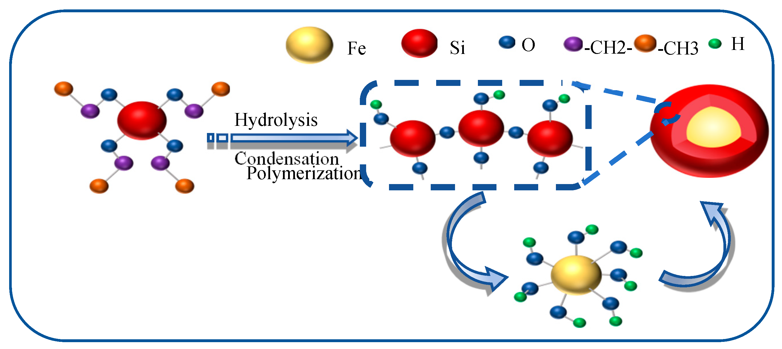
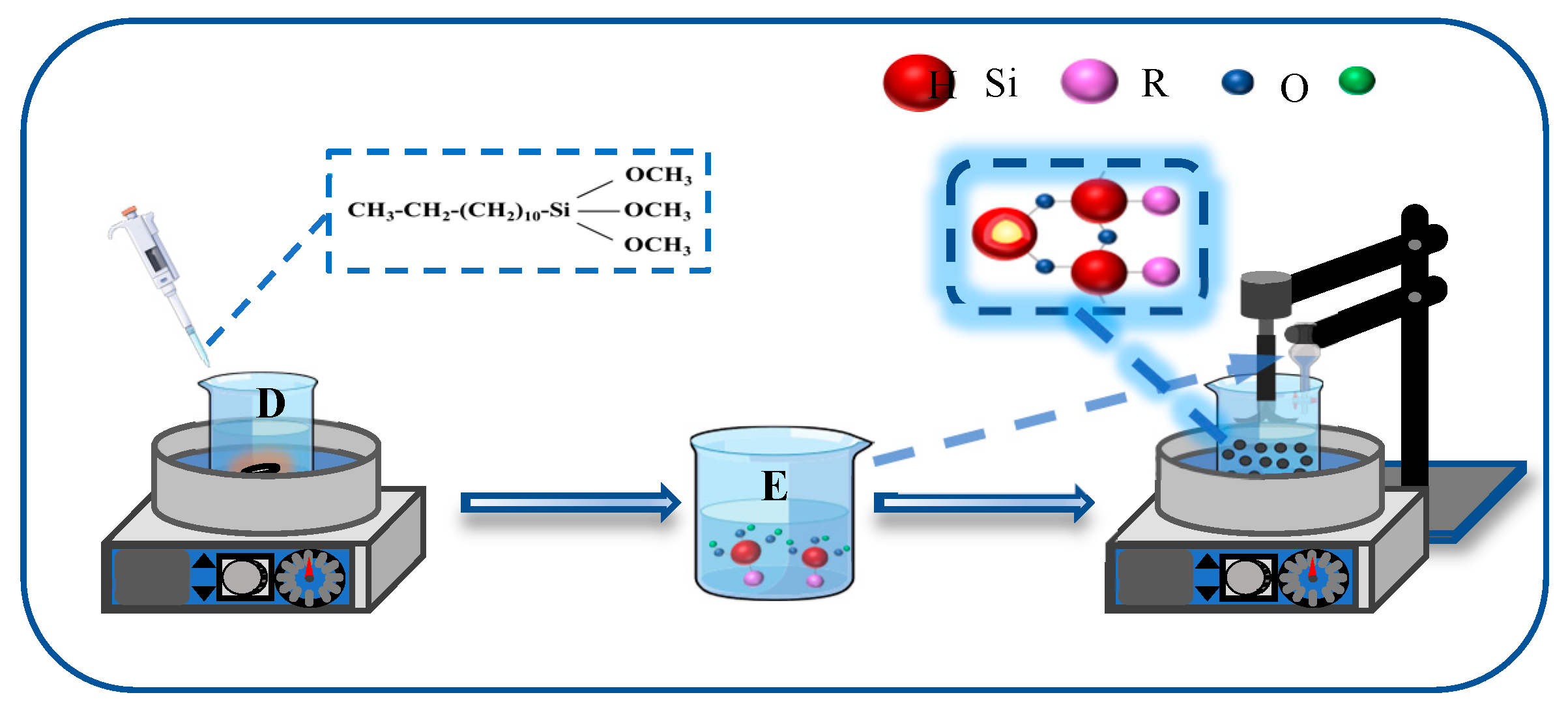
2.2.1. Modification of Fe3O4 NPs

To mitigate the mutual attraction between Fe3O4 NPs, a silica layer was deposited onto the Fe3O4 NPs using tetraethyl orthosilicate (TEOS) as the precursor. The synthesis of Fe3O4@SiO2 NPs was carried out via a modified Stöber method based on the sol–gel process, as illustrated in Figure 1. Specifically, 1 g of Fe3O4 NPs was dispersed in 50 mL of 0.1 mol/L HCl solution under ultrasonic (pulse mode: 5 s on/2 s off) treatment for 10 min to activate the hydroxyl groups on the surface of NPs, thereby facilitating the subsequent SiO2 coating. The Fe3O4 NPs were then washed five times with deionized water and ethanol to remove impurities, followed by dispersion in 80 mL of an ethanol solution (with a volume fraction of 80%). After ultrasonic dispersion for 10 min, the mixture was transferred to a stirring apparatus and stirred at 720 r/min for 20 min. Subsequently, 12 mL of NH3·H2O (with a concentration of 25~28%) was added, and the stirring was continued for an additional 30 min. Following this, varying volumes of tetraethyl orthosilicate (TEOS) (800 μL, 1000 μL, and 1200 μL) were introduced into C2H5OH/H2O solution (with a volume fraction of 80%) and stirred at room temperature for 5 h. The resulting solution was centrifuged, washed repeatedly with ethanol and deionized water (3–4 times), and dried at 70 °C for 12 h to obtain the Fe3O4@SiO2 NPs.
The synthesized Fe3O4@SiO2 nanoparticles (NPs) were further functionalized using dodecyltrimethoxysilane (KH-304), as depicted in Figure 2. Specifically, a measured quantity of KH-304 was introduced into 50 mL of 90% ethanol solution and subjected to hydrolysis under continuous stirring at 75 °C for 20 min, resulting in the formation of solution D. Concurrently, 0.2 g of Fe3O4@SiO2 NPs was dispersed in 50 mL of 90% ethanol solution via ultrasonication for 10 min to obtain solution E. Solutions D and E were then combined and stirred at 75 °C with a stirring speed of 400–450 rpm for 5 h. Following the reaction, the mixture was centrifuged, washed 3–4 times with ethanol and deionized water, and dried at 70 °C for 6 h to yield the surface-modified Fe3O4@SiO2 NPs.

2.2.2. Characterization Techniques

The morphological characteristics of the NPs were examined using scanning electron microscopy (SEM; ZEISS SUPRA-55, Oberkochen, Germany), and the particle size distribution was quantitatively assessed using Image-J software (V1.8.0.112). Surface functional groups of the NPs were analyzed by Fourier-transform infrared spectroscopy (FTIR; Nicolet 6700, Thermo Scientific, Waltham, MA, USA) employing the potassium bromide (KBr) pellet method. Additionally, the hydrophobicity of the modified NPs was evaluated by measuring the contact angle using a contact angle goniometer (JY-82A).

2.2.3. Evaluation of Foam Stabilization and NPs Recovery

The foam stability was assessed using the Waring blender method [36]. Specifically, Fe3O4@SiO2 NPs with different wettability modifications (0.2 wt%) were dispersed in 200 mL of a 0.2 wt% AOS solution using an ultrasonic disperser to prepare a homogeneous Fe3O4@SiO2 (0.2 wt%)-AOS (0.2 wt%) dispersion. The dispersion was then foamed using a high-speed blender (8011ES, Waring, Stamford, CT, USA) at 5000 rpm for 3 min, and the resulting foam was transferred to a graduated cylinder. Foamability was characterized by measuring the initial foam volume, while foam stability was evaluated based on the drainage half-life, defined as the time required for half of the liquid to drain. The NPs exhibiting the optimal contact angle were selected for further foam-stabilization experiments. After foam collapse, the mixed solution was subjected to an external magnetic field to facilitate NP sedimentation. The recovered NPs were washed with distilled water and reused for subsequent foam-stabilization tests. The changes in foam half-life were recorded to evaluate the reusability and performance of NPs.

2.2.4. Adsorption of NPs on Liquid Films

The distribution of NPs within the foam system was investigated using a fluorescence microscope (Trim Scope, Wilnsdorf, Germany) to elucidate the stabilization mechanism of Fe3O4@SiO2 NPs in foam. For this purpose, the fluorescent probe rhodamine B, which carries a negative charge and exhibits a maximum excitation wavelength of 543 nm, was employed to label the NPs in the dispersion. The stained NPs were subsequently centrifuged and washed repeatedly with distilled water until the supernatant became clear. The labeled NPs were then utilized to generate foam, and fluorescence images of the foam were captured using the microscope to analyze the spatial distribution and behavior of NPs within the foam structure.

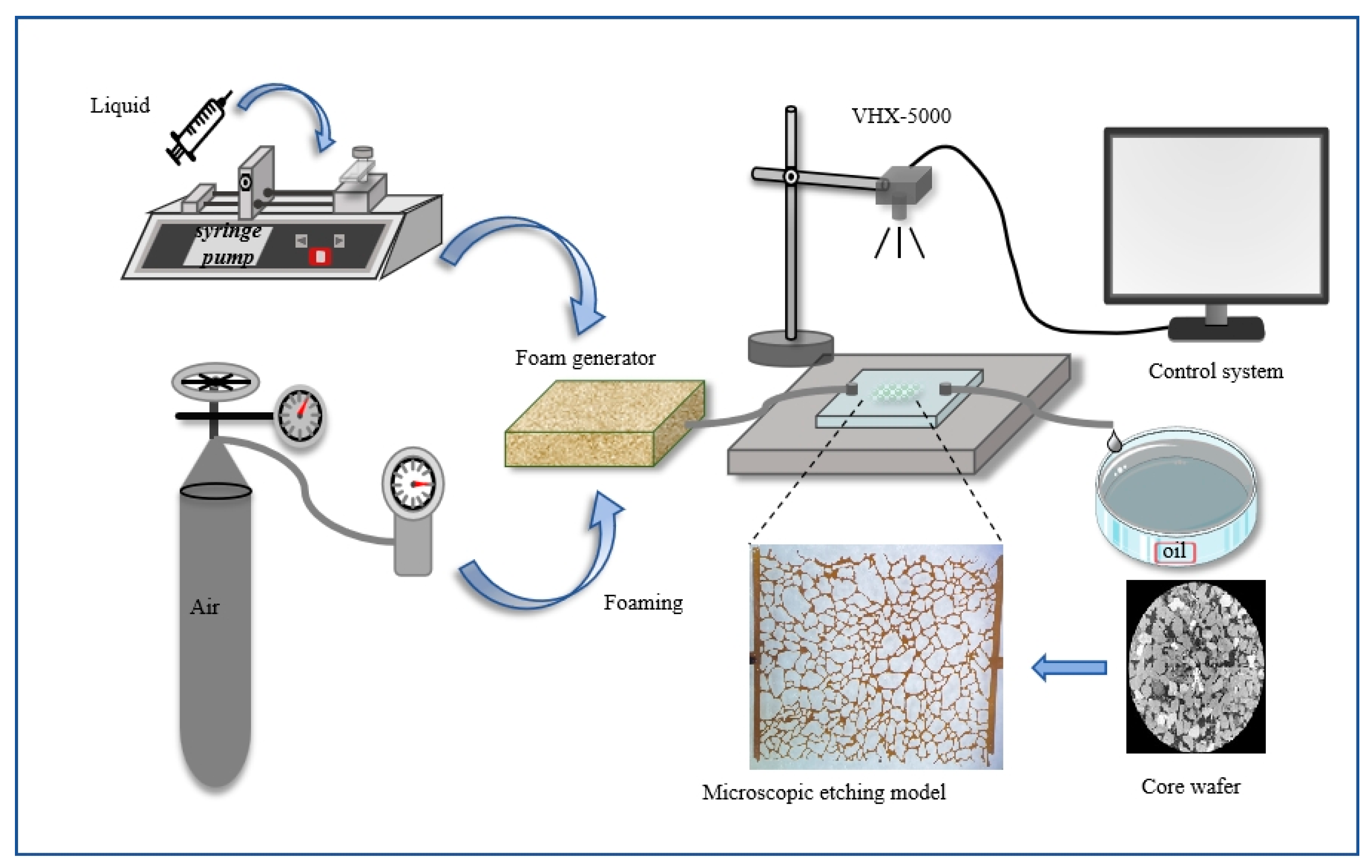
2.2.5. Microscopic Oil Displacement Experiment

Microscopic oil displacement experiments were conducted using a micro-etched porous media model designed to replicate the natural pore structure of cores from the Daqing oilfield. The pore network was etched onto a glass plate using photolithography, and the etched plate was bonded to a smooth glass plate to create the microscopic model. The fabricated glass micromodel exhibited a porosity of 25%, with an average pore depth of approximately 40 μm and a pore width of approximately 100 μm. The experimental setup, as illustrated in Figure 3, comprised a foam generation device, a microscopic pore model, and an observation data acquisition system.
Prior to the experiment, the micromodel was evacuated and saturated with crude oil (viscosity = 7.69 mPa·s at 25 °C). Water flooding was initiated by injecting 5 pore volumes (PVs) of water until water without oil was produced. Foam was generated by co-injecting a foam solution and air at a 1:1 volume ratio into the foam generator. Subsequently, 2.5 PVs of either AOS foam or Fe3O4@SiO2-AOS-stabilized foam were injected, followed by 2.5 PVs of water flooding at a constant injection rate of 1 μL/min. The entire displacement process was monitored and recorded using a microscope (VHX-5000, Keyence, Osaka, Japan) equipped with a high-resolution CCD camera and a parallel light source. The experiments focused on investigating the mobilization of various types of residual oil by Fe3O4@SiO2-stabilized foam under high water-saturation conditions at 25 °C.
After the experiment, the micromodel was cleaned by injecting petroleum ether and ethanol to remove residual oil and ensure all pores and throats were free of contaminants. The micromodel was then dried in a constant temperature oven at 45 °C for subsequent use.

3. Results

3.1. Characterization of NPs

Following the modification process, a portion of the hydroxyl (-OH) groups on the surface of the NPs were substituted with carbon chains, resulting in a reduction in saturation magnetization. The successful formation of the modified NPs was confirmed through comprehensive characterization using scanning electron microscopy (SEM), transmission electron microscopy (TEM), and Fourier-transform infrared spectroscopy (FTIR). These techniques were employed to evaluate the morphological and structural changes, as well as to analyze the surface functional groups of the modified NPs.

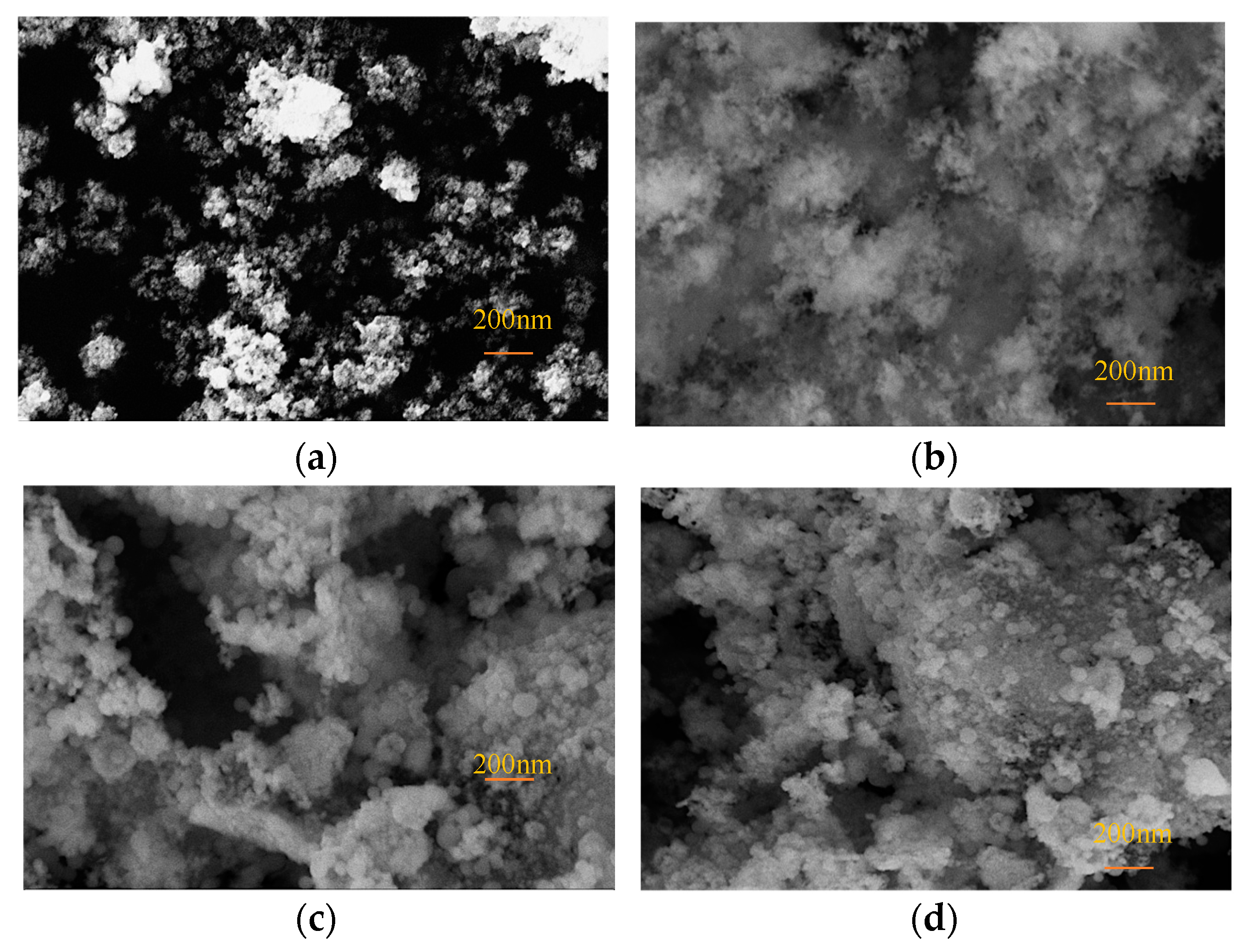
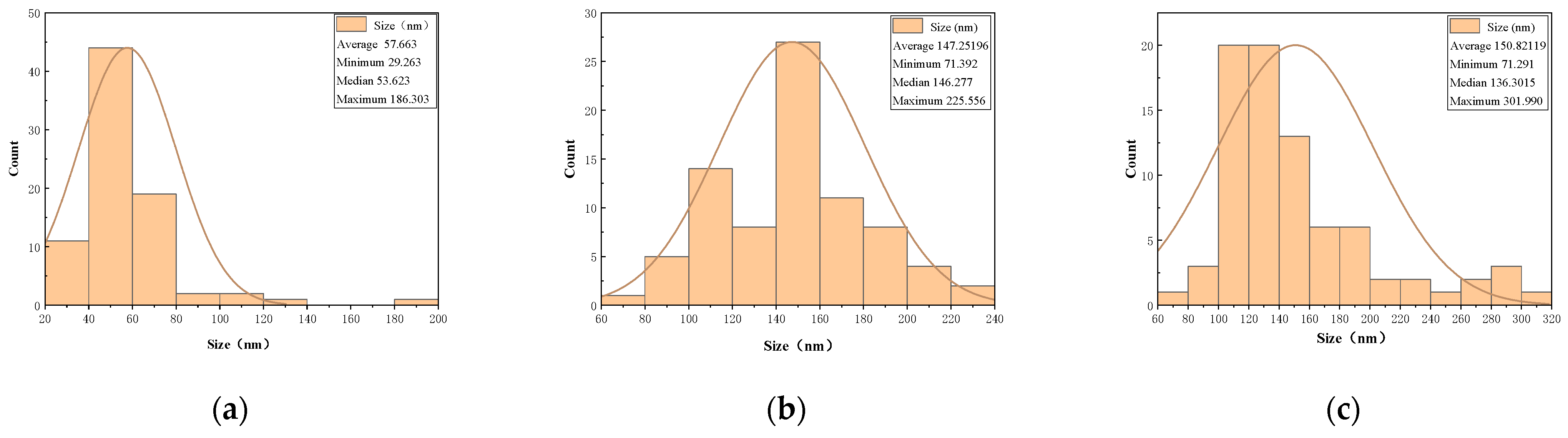
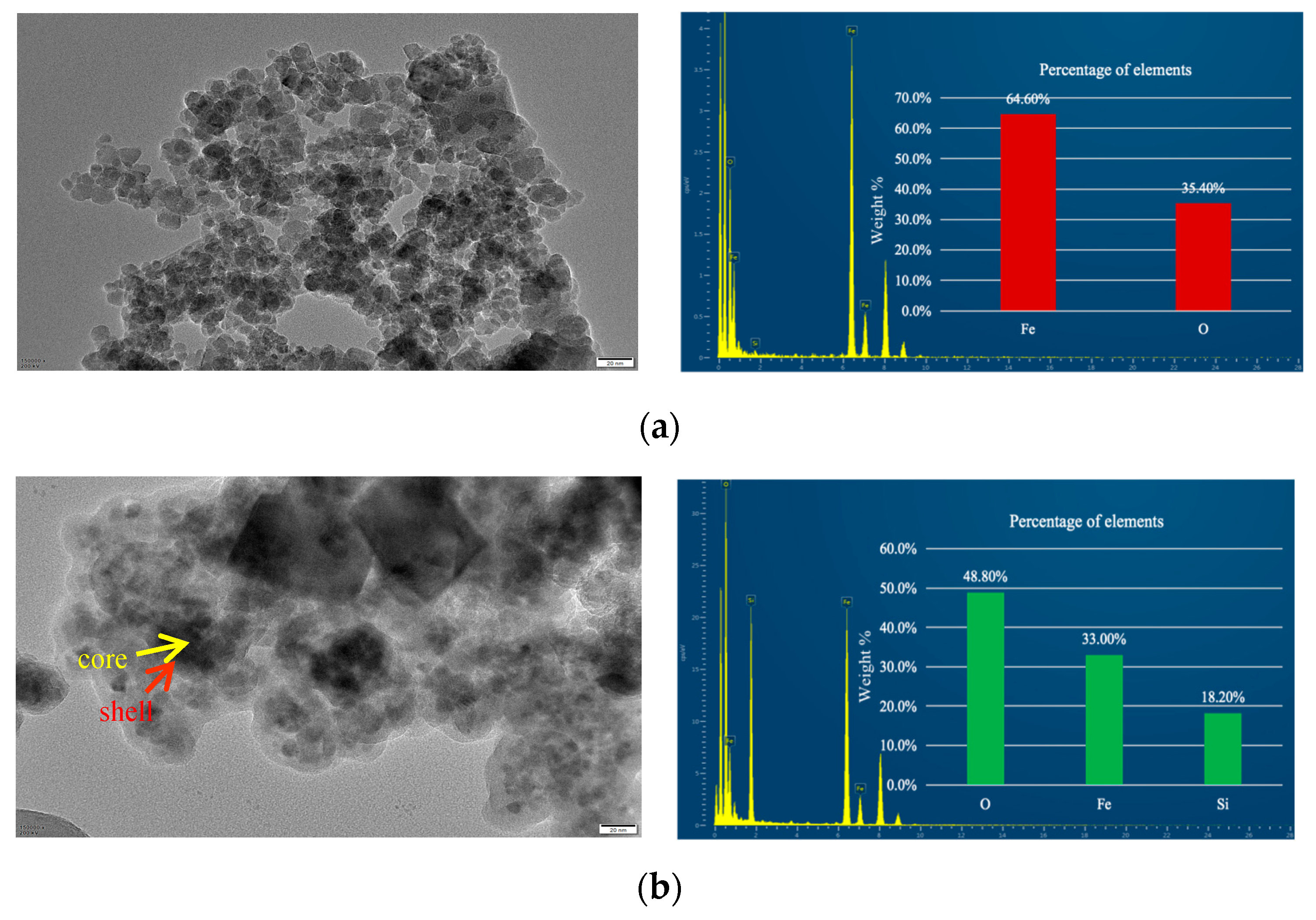
3.1.1. Morphological Analysis

The SEM images of Fe3O4@SiO2 NPs synthesized with varying amounts of TEOS (800 μL, 1000 μL, and 1200 μL) are presented in Figure 4, illustrating the morphological and size characteristics of the NPs. Following the SiO2 coating process, the particle size increased significantly from 20 nm to approximately 300 nm. The SEM analysis also revealed the enhanced dispersibility of NPs after coating. As depicted in Figure 4a, bare Fe3O4 NPs displayed irregular shapes and pronounced agglomeration. In contrast, Figure 4b shows Fe3O4@SiO2-800 NPs, which exhibited a flocculent structure with reduced agglomeration, suggesting that the SiO2 coating mitigated the interparticle interactions of Fe3O4 NPs. However, due to the insufficient amount of TEOS, a well-defined spherical core–shell structure was not achieved. Figure 4c,d display Fe3O4@SiO2-1000 NPs and Fe3O4@SiO2-1200 NPs, respectively. These NPs demonstrated spherical morphologies, significantly larger particle sizes, reduced agglomeration, and more uniform structures, confirming the successful formation of an SiO2 coating on the Fe3O4 NPs’ surface.
To evaluate the size distribution of Fe3O4@SiO2-1000 NPs and Fe3O4@SiO2-1200 NPs, particle size analysis was conducted using Image-J software by randomly selecting 80 points from each SEM image. The results are presented in Figure 5. As depicted in Figure 5a, the particle size distribution of bare Fe3O4 NPs ranges from 20 to 200 nm, with an average diameter of 57.663 nm. Figure 5b illustrates that the particle size distribution of Fe3O4@SiO2-1000 NPs spans from 60 to 240 nm, with an average diameter of 147.252 nm. Similarly, Figure 5c demonstrates that the particle size distribution of Fe3O4@SiO2-1200 NPs extends from 60 to 320 nm, with an average diameter of 158.021 nm. These findings indicate a significant increase in the diameter of the NPs following the core–shell coating process, with the particle size positively correlated with the amount of TEOS used. Furthermore, compared with Fe3O4@SiO2-1200 NPs, Fe3O4@SiO2-1000 NPs exhibit a narrower particle size distribution, a smaller average particle size, and enhanced uniformity. Consequently, 1000 μL of TEOS was determined to be the optimal amount for coating the Fe3O4 NPs.
To visually confirm the formation of the core–shell structure, the NPs were characterized using TEM and Energy-Dispersive X-ray Spectroscopy (EDS), as illustrated in Figure 6. In Figure 6a, the bare Fe3O4 NPs exhibit a uniform granular morphology, consistent with the observations from SEM imaging. Figure 6b reveals the core–shell structure of Fe3O4@SiO2-1000 NPs, where the core (Fe3O4) appears darker, smaller, and denser, while the shell (SiO2) appears lighter, larger, and forms a well-defined spherical coating. This confirms the successful deposition of a silica shell on the surface of the Fe3O4 NPs.
To further validate the chemical composition of the materials, EDS analysis was performed. The results indicate that the bare Fe3O4 NPs consist of 64.6% Fe and 35.4% O, whereas the SiO2-coated Fe3O4 NPs comprise 48.8% O, 33.0% Fe, and 18.2% Si. The presence of a weak Si peak alongside a strong Fe peak provides additional evidence for the successful formation of a silica shell on the surface of the Fe3O4 NPs. These findings collectively demonstrate the effective synthesis of the core–shell structure.

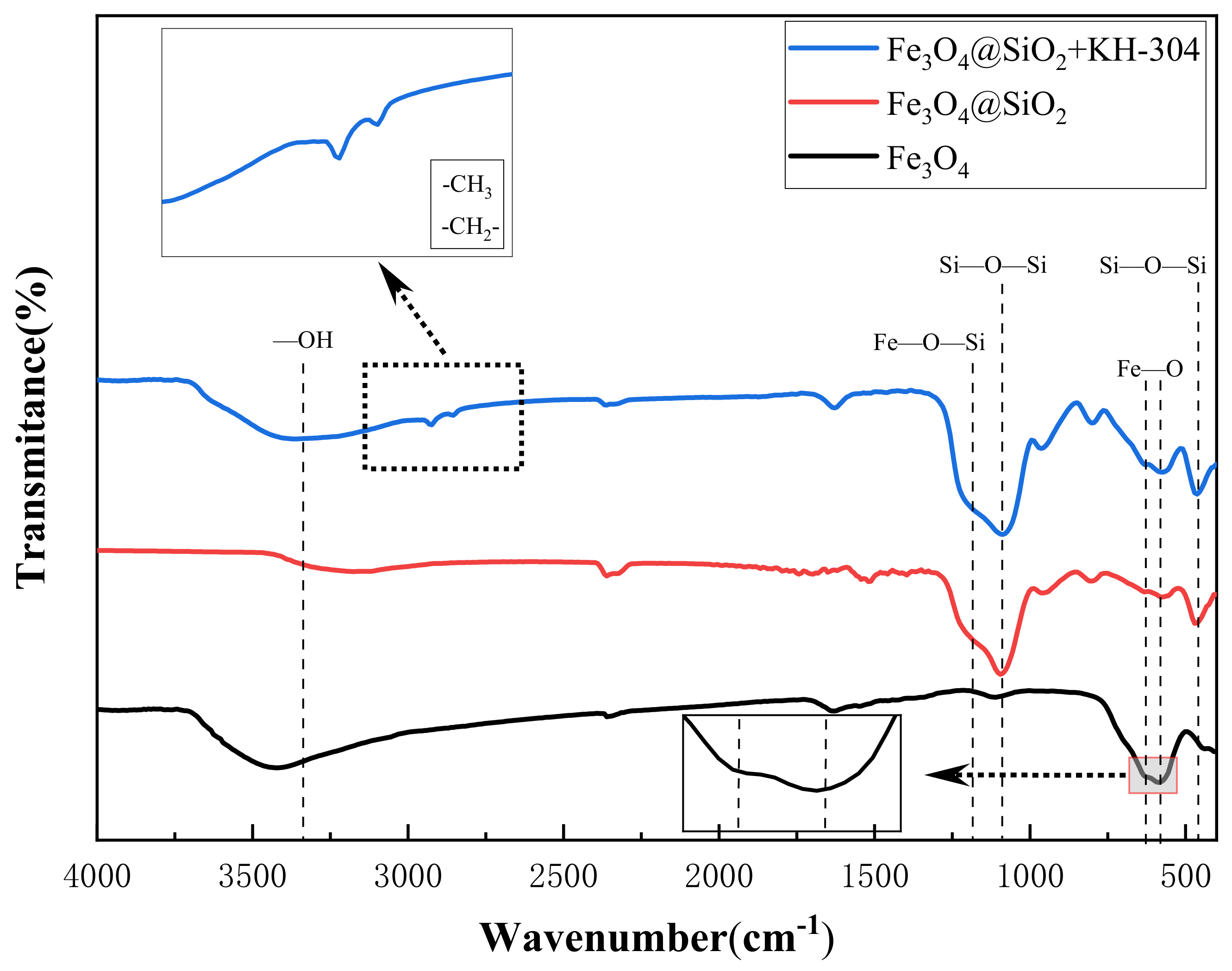
3.1.2. FTIR Analysis

FTIR analysis was employed to confirm the presence of grafted functional groups and the successful formation of modified NPs, as depicted in Figure 7. In all four spectra, the characteristic Fe-O bond vibration peak was observed at 586 cm−1 and 630 cm−1, confirming the presence of Fe3O4. Additionally, peaks corresponding to -OH stretching and bending vibrations were identified at 3310 cm−1 and 1627 cm−1, respectively [37]. A strong absorption peak at 1082 cm−1 was attributed to the asymmetric stretching vibration of the Si-O-Si bond, while the peak at 462 cm−1 represented the bending vibration of the Si-O-Si bond, both of which are indicative of the SiO2 coating. The peak at 1123 cm−1, corresponding to the Fe-O-Si stretching vibration, further confirmed the successful formation of the SiO2 coating and the core–shell structure. In the FTIR spectrum of Fe3O4@SiO2+KH-304, the peaks observed at 2924 cm−1 and 2831 cm−1 were assigned to the asymmetric stretching vibrations of the -CH3 and -CH2 groups, respectively, indicating the presence of carbon chains on the NP surface [38]. Since these carbon chains originate from the hydrophobic modifier KH-304, these results provide clear evidence of the successful hydrophobic modification of the NPs.

3.2. Analysis of Surface Hydrophobicity and Foam-Stabilization Ability of Modified NPs

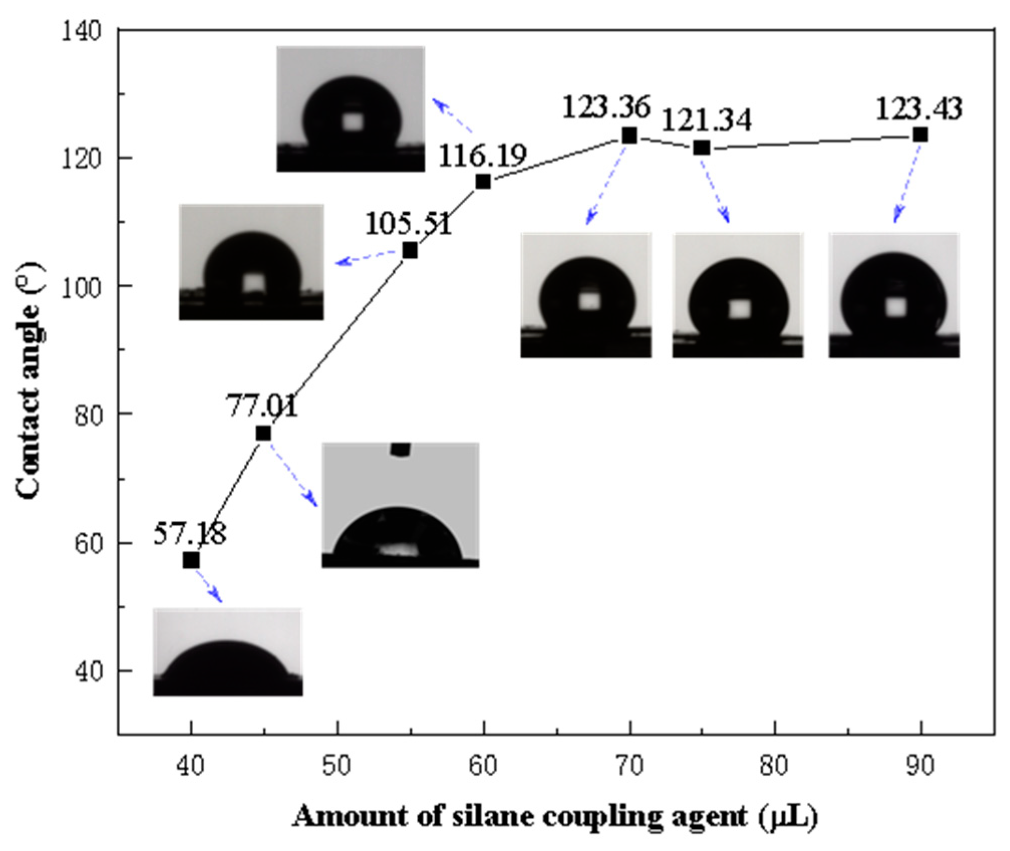
3.2.1. Analysis of Surface Hydrophobicity of Modified NPs

NPs must exhibit moderate hydrophobicity to ensure strong adsorption at the gas–liquid interface. However, excessively hydrophobic NPs are ineffective in stabilizing foam, as they fail to adsorb onto the lamellae and prevent liquid drainage [39]. Therefore, it is crucial to select NPs with an optimal level of hydrophobicity.
The contact angles of Fe3O4@SiO2-1000-KH-304 NPs, modified with varying amounts of KH-304, were measured, as illustrated in Figure 8. As the concentration of KH-304 increased, the contact angle between the NPs and water progressively rose from 57.18° to 121.34°, after which it plateaued, indicating that further increases in the modifier did not alter the contact angle. To investigate the influence of NPs with different wettabilities on foam stability, NPs with contact angles of 57.18°, 77.01°, 105.51°, and 121.34° were selected for subsequent foam stability experiments.

3.2.2. Analysis of Foam-Stabilization Ability of Modified NPs

Foam was generated by high-speed stirring of a foaming solution containing Fe3O4@SiO2-1000-KH-304 NPs with varying hydrophobicities and alpha-olefin sulfonate (AOS) at a concentration of 0.2 wt%. The drainage half-life and initial foam volume were measured and are presented in Figure 9. The results demonstrated that the foam-stabilization effect was optimal at an NP concentration of 1.0 wt% and a contact angle of 77.01°, achieving a drainage half-life of 452 s and an initial foam volume of 664 mL. In contrast, at the same NP concentration of 1.0 wt%, the foam-stabilization capability was weakest for NPs with a contact angle of 123.3°, exhibiting a drainage half-life of only 374 s, which was lower than that of unmodified NPs.

3.2.3. Adsorption of NPs on Foam Surfaces

To elucidate the mechanism by which Fe3O4@SiO2 NPs stabilize foam, the NPs were labeled with a fluorescent dye, and their distribution within the foam system was observed using fluorescence microscopy, as illustrated in Figure 10. Figure 10a reveals that the NPs were predominantly distributed in the liquid phase between bubbles. To more clearly visualize the particle distribution, the foam was drained to form dry foam. In the Fe3O4@SiO2 NPs-AOS (0.2 wt%) system, significant NP loss was observed, with few NPs adsorbed on the liquid film, as shown in Figure 10b. In contrast, the majority of Fe3O4@SiO2 NPs with a contact angle of 77.01° were adsorbed onto the liquid film of the bubbles and remained in place even after liquid drainage, as depicted in Figure 10c. Conversely, Fe3O4@SiO2 NPs with a contact angle of 121.34° tended to migrate out of the liquid phase and into the gas phase, with minimal adsorption on the liquid film, as shown in Figure 10d.
These observations indicate that NPs located in the surrounding continuous liquid phase are carried away during liquid drainage, whereas NPs adsorbed at the gas–liquid interface remain within the dry foam skeleton after drainage. Specifically, NPs with a contact angle of 77.01° adsorb onto the bubble surface, forming a protective particle armor. Unmodified core–shell NPs, being more hydrophilic, predominantly reside in the liquid phase, while NPs with a contact angle of 121.34°, due to their stronger hydrophobicity, preferentially remain in the gas phase. These findings highlight the critical role of NPs’ hydrophobicity in determining their distribution and foam-stabilizing behavior.

3.3. Recyclability of NPs

Fe3O4 NPs exhibit a high responsiveness to external magnetic fields. Consequently, after assessing foam stability, the NPs were recovered using an external magnetic field and reused for foam stabilization. The foam solution employed for recyclability evaluation consisted of 1 wt% Fe3O4@SiO2 NPs (77.01°) and 0.2 wt% AOS, representing the optimal system identified earlier. Following foam generation, the foam half-life was recorded. The NPs were then recovered by applying a magnetic field, washed multiple times with ethanol and deionized water, and reused for foam stabilization until a significant reduction in drainage half-life was observed.
As shown in Figure 11a, the mixed solution exhibited a noticeable lightening in color after 5 min, with a mound of NPs settling at the bottom after 10 min. The solution became clear after 20 min, and the NPs were completely aggregated at the bottom of the container under the influence of the external magnetic field. This demonstrates that the modified NPs retain a high sensitivity to external magnetic fields and can be efficiently recovered. Figure 11b illustrates that foam stability was minimally affected during the first three recovery cycles, with a reduction in drainage half-life of only 2–7%. However, after the fourth recovery cycle, the drainage half-life decreased significantly, negatively impacting foam stability, with a 19% reduction observed by the fifth cycle. Therefore, to maintain optimal foam stability, the NPs should be recovered and reused no more than three times.

3.4. Microscopic Oil Displacement Mechanism of Modified NPs

Water, AOS foam (0.2 wt%), and Fe3O4@SiO2 (0.1 wt%)-AOS (0.2 wt%) foam with a contact angle of 77.01° were employed for oil displacement experiments. The displacement process of specific types of residual oil within a fixed area was monitored in real-time using microscopy. Figure 12 illustrates the effects of the three displacement agents on clustered, membranous, and dead-end residual oil. Due to the high water–oil mobility ratio, water flooding tends to bypass oil, causing water channeling through larger pores and leaving oil trapped in smaller pores, resulting in the formation of clustered residual oil, as depicted in Figure 12a. Membranous residual oil is predominantly distributed in water-flooded regions, where oil adheres to pore surfaces and is not fully displaced by water or surfactant solutions, as shown in Figure 12b. Dead-end residual oil is commonly found in rock formations, characterized by pores connected to the pore-throat network at only one end. Owing to the low viscosity of water, it cannot penetrate dead-end pores, leading to the retention of dead-end residual oil, as illustrated in Figure 12c.
Compared with water flooding, AOS foam demonstrates a stronger capability to mobilize these three types of residual oil. However, Fe3O4@SiO2 (0.1 wt%)-AOS (0.2 wt%) foam exhibits an even more effective displacement performance for these residual oils. As illustrated in the injection pressure curve (Figure 13), the pressure generated during the injection of AOS foam (0.2 wt%) is significantly higher than that of water injection. Furthermore, the injection pressure of Fe3O4@SiO2 (0.1 wt%)-AOS (0.2 wt%) foam is markedly greater than that of AOS foam alone. This indicates that Fe3O4@SiO2 (0.1 wt%)-AOS (0.2 wt%) foam can more effectively perform plugging and profile control functions, thereby enhancing the displacement efficiency of the injected fluid. The enhanced performance is attributed to the synergistic effects of the NPs and foam, which improve the stability and viscoelasticity of the displacing fluid, thereby enhancing its ability to access and displace oil from complex pore structures.
To investigate the mechanism by which Fe3O4@SiO2-(0.1 wt%)-AOS (0.2 wt%) foam with a contact angle of 77.01° mobilizes the three types of residual oil, typical images of the displacement process are shown in Figure 14. As shown in Figure 14a, the foam stabilized by modified Fe3O4@SiO2 NPs blocked the water channeling paths around the clustered residual oil, allowing bubbles to enter low-permeability pores, emulsifying and dispersing the clustered residual oil into membranous oil or small oil droplets, which were then displaced. As shown in Figure 14b, the mobilization of membranous residual oil by modified Fe3O4@SiO2 NP-stabilized foam occurred in two stages: first, the foam emulsified and peeled off the oil attached to the pore surfaces, reducing the difficulty of displacement; second, due to the adsorption of NPs, foam stability was improved, reducing gas diffusion between bubbles and the surface area of the dispersed residual oil, allowing the foam to continuously regenerate and propagate in narrow pores, pushing the oil droplets out. As shown in Figure 14c, the foam stabilized by Fe3O4@SiO2-AOS had good stability, maintaining relatively small bubbles for a longer time, reducing the flow resistance when entering dead-end pores, and allowing deeper penetration into oil-containing dead-end pores. In the dead-end pores, the bubbles deformed under the driving force due to the higher interfacial viscoelasticity of Fe3O4@SiO2-AOS bubbles. The deformed bubbles tended to restore their original shape, gradually replacing the residual oil with films or droplets, and effectively displacing oil from the dead-end pores.
The residual oil in the micromodel was recorded using a microscope, and the images were processed using Image-J software, as shown in Figure 15, to quantitatively calculate the oil recovery rate. Figure 15a,e show the initial oil-saturated state of the micromodel, while Figure 15b–d,f–h show the residual oil after water flooding, foam flooding, and modified NP-stabilized foam flooding, respectively. Compared with the water flooding recovery rate of 42.07%, foam flooding effectively improved the sweep efficiency, compensating for the shortcomings of water flooding and increasing the recovery rate by approximately 16%. However, significant residual oil remained after foam flooding. In contrast, the modified NP-stabilized foam flooding had a larger sweep efficiency and higher displacement efficiency, achieving a recovery rate of 75.40%, an increase of 33.33% compared with water flooding.

4. Conclusions

Through shell coating and hydrophobic modification experiments on Fe3O4 NPs, Fe3O4@SiO2 NPs with different wettabilities were prepared, and their foam-stabilization performance was evaluated. The effects of modified NPs on foam stability were assessed through static foam stability experiments, including drainage half-life and initial foam volume. The foam-stabilization mechanism of Fe3O4@SiO2 NPs was investigated using confocal laser scanning microscopy. Microscopic oil displacement experiments were conducted to evaluate the enhanced oil recovery mechanism of modified NP-stabilized foam.
The main findings are as follows:
(1)
The characterization of the prepared NPs and foam stability evaluation showed that Fe3O4@SiO2-1.0 NPs with a contact angle of 77.01° had the best foam-stabilization performance, significantly improving foam stability. The optimal foam system consisted of 1 wt% NPs (77.01°) + 0.2 wt% SDS, with a drainage half-life of 452 s and an initial foam volume of 510 mL.
(2)
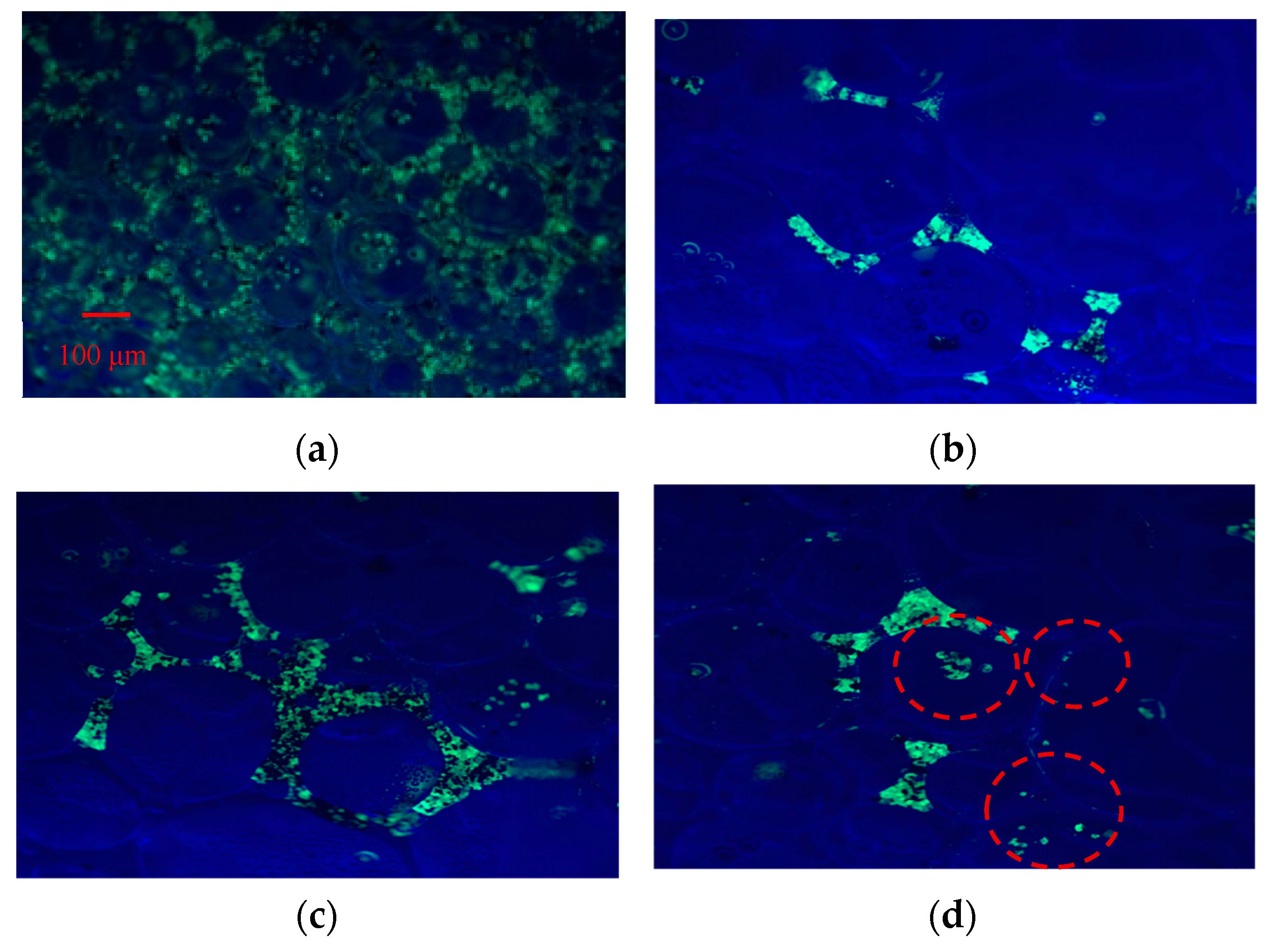
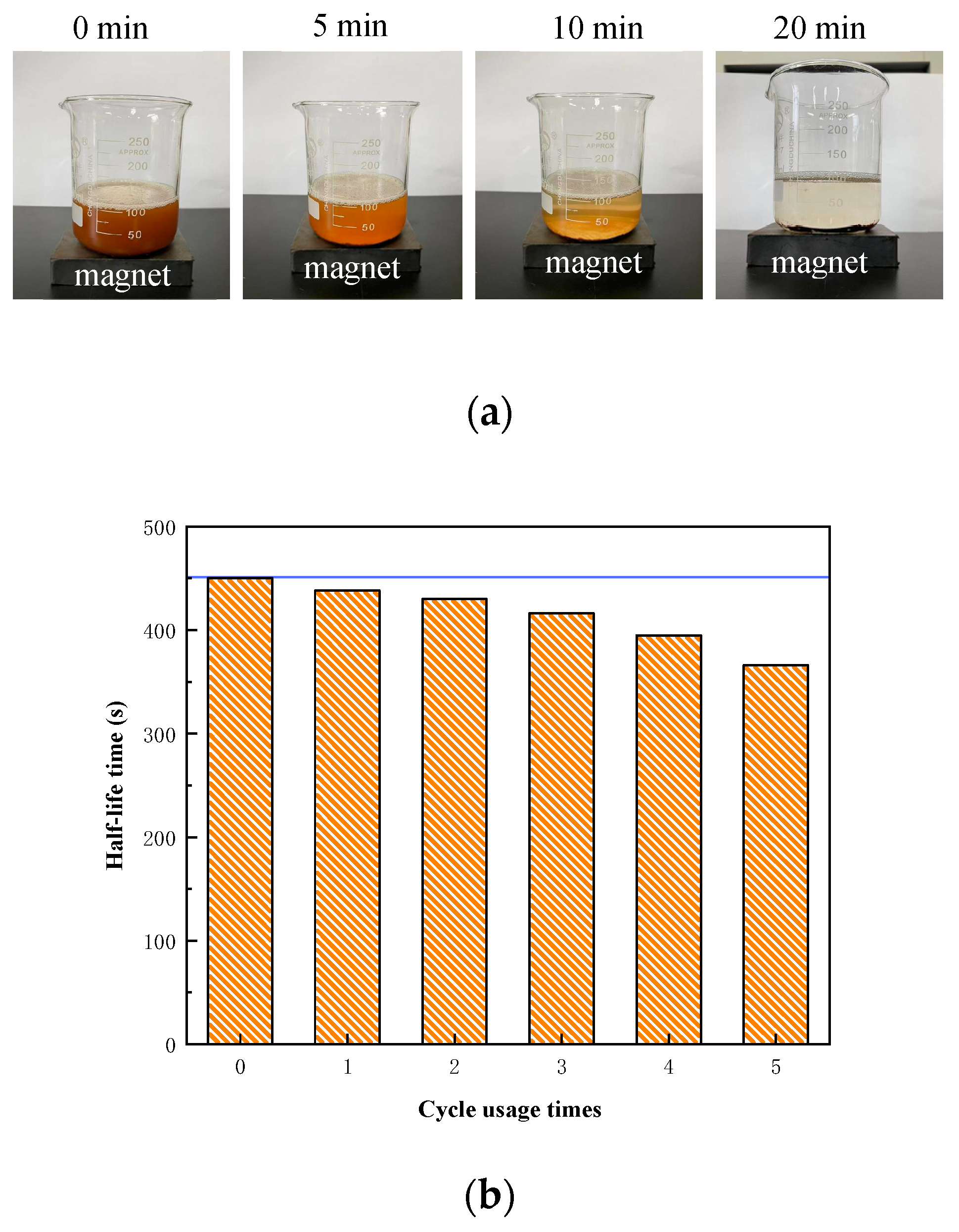
Confocal laser scanning microscopy experiments showed that the modified Fe3O4@SiO2 NPs were adsorbed on the bubble surface, forming a three-dimensional network structure between armored bubbles, thereby enhancing foam stability. A static foam stability evaluation indicated that the optimal number of NP recovery cycles was three, and Fe3O4@SiO2 NPs responded quickly to magnetic fields.
(3)
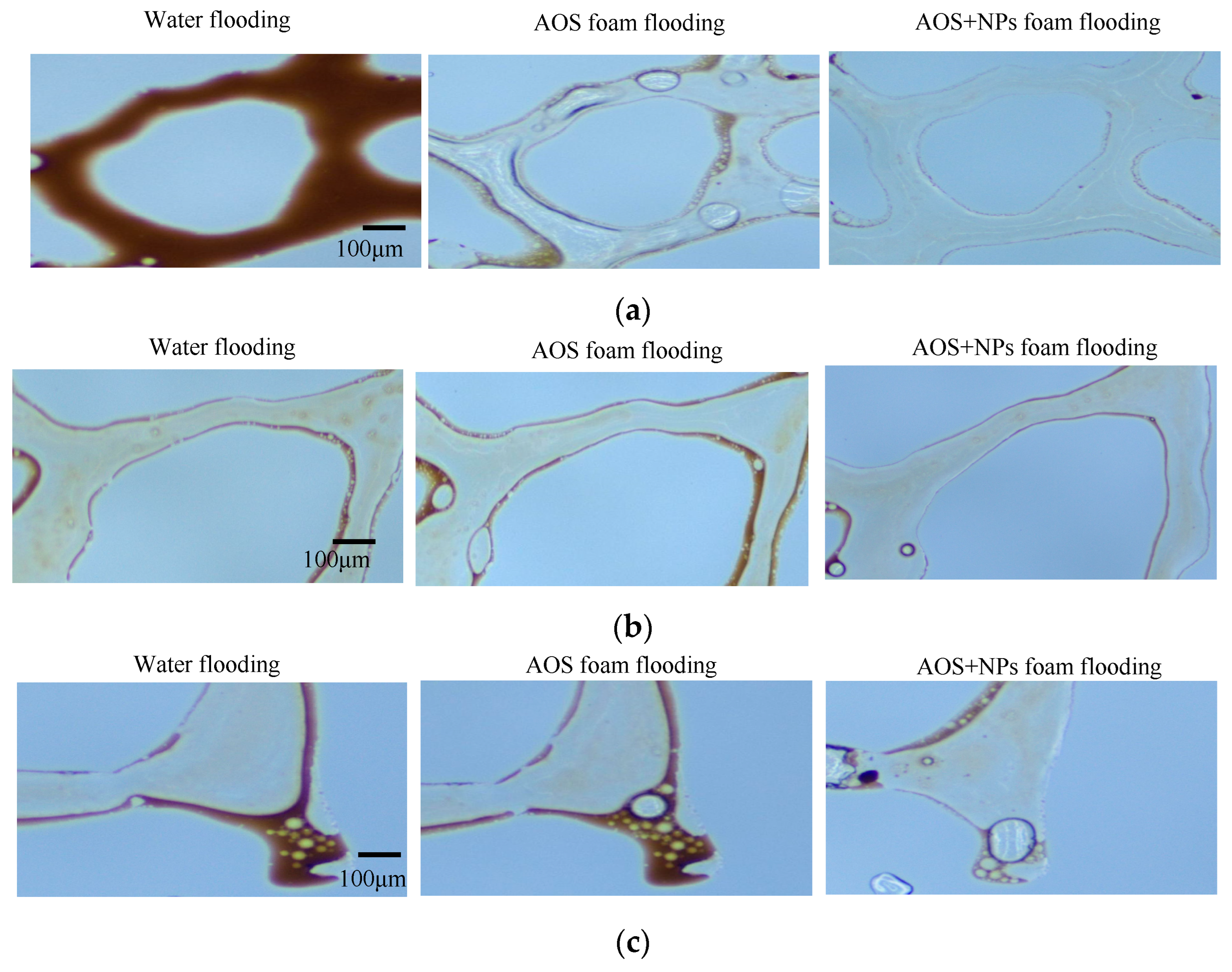
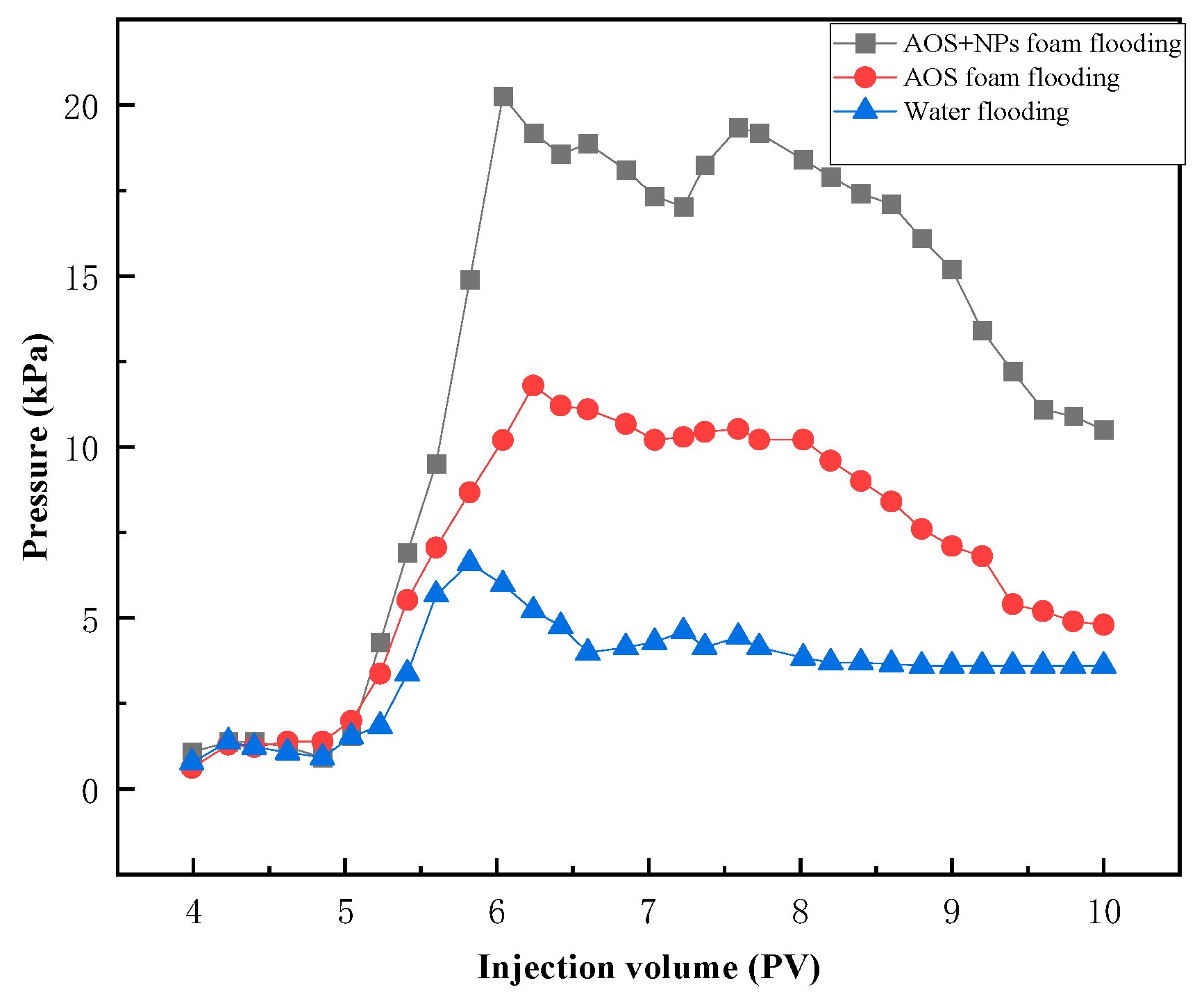
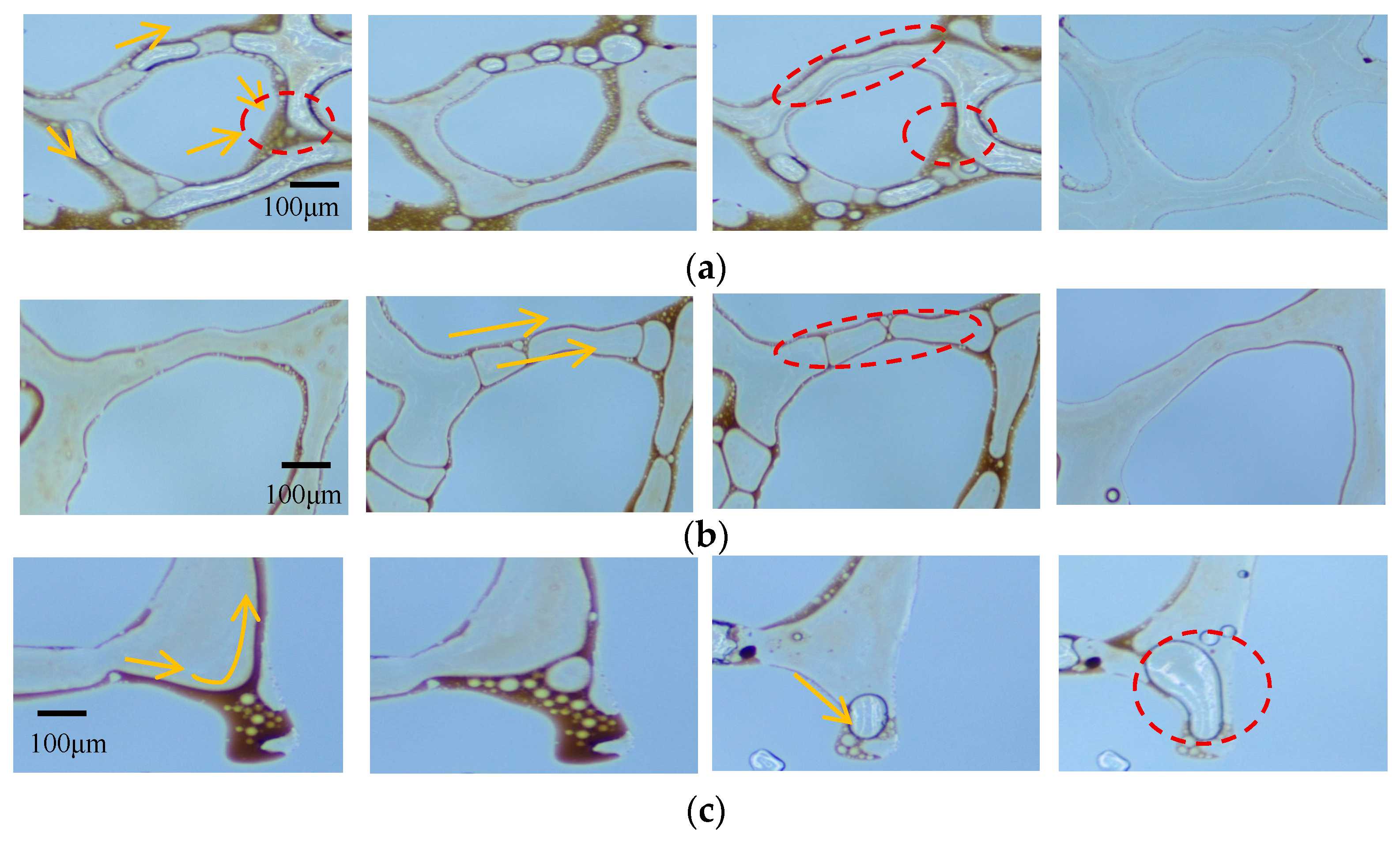
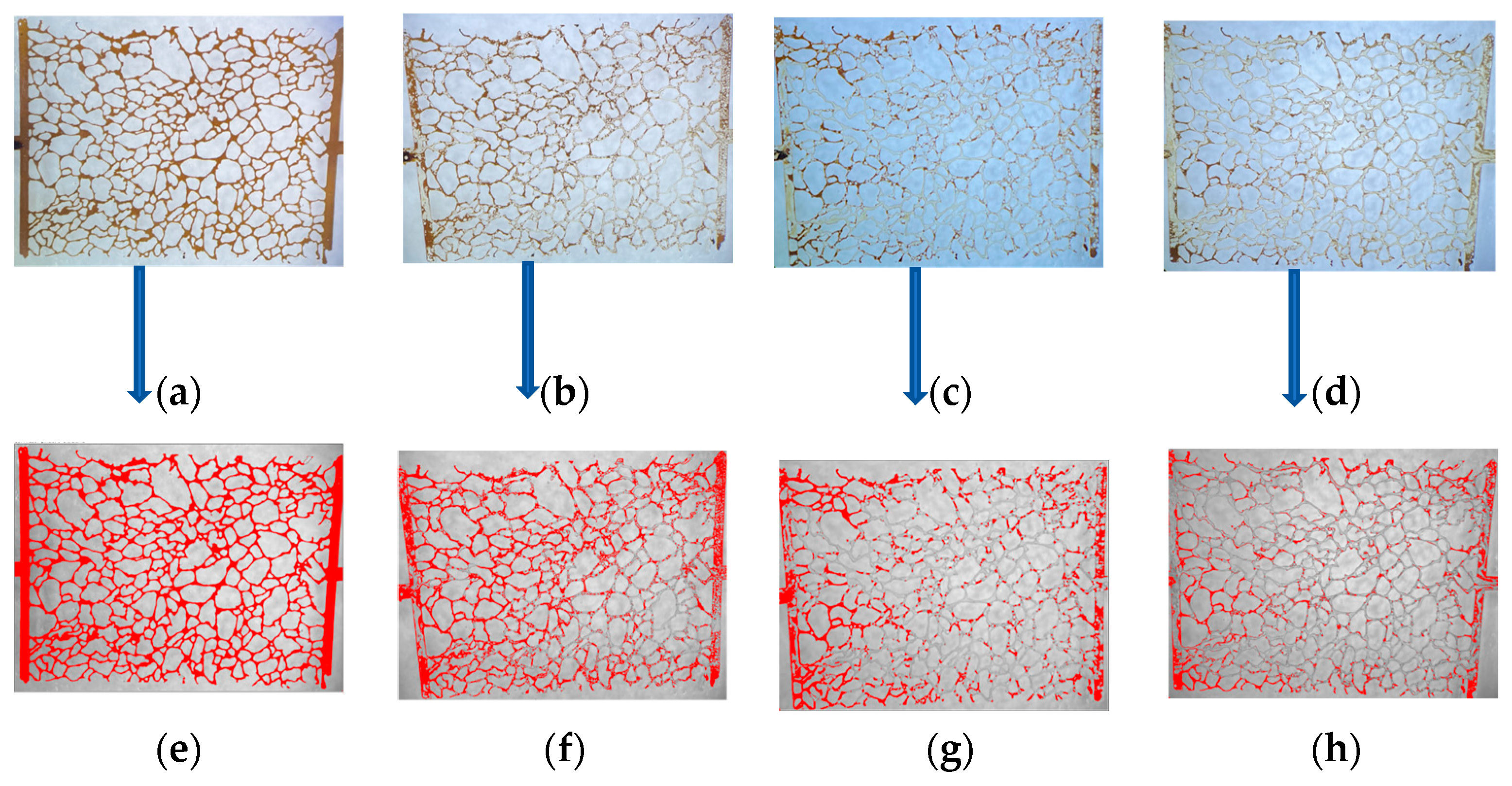
Microscopic visual oil displacement experiments demonstrated that, compared with AOS foam alone, Fe3O4@SiO2-1000 NP-stabilized foam had a higher ability to mobilize residual oil. The foam’s strong stability blocked large pores, allowing subsequent fluids to enter small pores, emulsifying and mobilizing clustered residual oil. The dense adsorption of modified Fe3O4 NPs at the liquid film interface significantly enhances film strength, enabling bubbles to undergo elastic deformation rather than rupture when passing through pore throats, emulsifying and peeling off membranous residual oil and pushing it out. Bubbles entered dead-end pores through high viscoelastic deformation, carrying out residual oil. Compared with the water flooding recovery rate of 42.07%, the modified NP-stabilized foam achieved a recovery rate of 75.40%, an increase of 33.33%, effectively mobilizing residual oil.

Author Contributions

Conceptualization, D.Y. and D.Z.; methodology, Y.W.; formal analysis, Y.W.; investigation, J.Q.; resources, D.Z.; data curation, J.Q.; writing—original draft preparation, D.Z.; writing—review and editing, D.Y.; visualization, T.H.; supervision, X.H.; project administration, Y.L.; funding acquisition, D.Y. All authors have read and agreed to the published version of the manuscript.

Funding

This research was funded by the National Natural Science Foundation of China (Nos. 52004247 and 51604243) and Zhoushan Science and Technology Bureau (No. 2021C21024), China Scholarship Council.

Data Availability Statement

The authors confirm that the data supporting the findings of this study are available within the article.

Conflicts of Interest

The authors declare no conflicts of interest. The funders had no role in the design of the study; in the collection, analyses, or interpretation of data; in the writing of the manuscript; or in the decision to publish the results.

References

  1. Lake, L.W.; Johns, R.; Rossen, B.; Pope, G.A. Fundamentals of Enhanced Oil Recovery; Society of Petroleum Engineers: Richardson, TX, USA, 2014; Volume 1. [Google Scholar]
  2. Kovscek, A.R.; Radke, C.J. Fundamentals of Foam Transport in Porous Media; Lawrence Berkeley National Lab. (LBNL): Berkeley, CA, USA, 1993. [Google Scholar]
  3. Rossen, W.R. Foams in enhanced oil recovery. In Foams; Routledge: London, UK, 2017; pp. 413–464. [Google Scholar]
  4. Farajzadeh, R.; Andrianov, A.; Krastev, R.; Rossen, W.; Hirasaki, G. Foam-oil interaction in porous media-Implications for foam-assisted enhanced oil recovery (SPE 154197). In Proceedings of the 74th EAGE Conference and Exhibition Incorporating EUROPEC, Copenhagen, Denmark, 4–7 June 2012; p. cp-293-00225. [Google Scholar]
  5. Simjoo, M.; Rezaei, T.; Andrianov, A.; Zitha, P. Foam stability in the presence of oil: Effect of surfactant concentration and oil type. Colloids Surf. A Physicochem. Eng. Asp. 2013, 438, 148–158. [Google Scholar] [CrossRef]
  6. Schramm, L.L. Foams: Fundamentals and Applications in the Petroleum Industry; ACS Publications: Washington, DC, USA, 1994. [Google Scholar]
  7. Nowrouzi, I.; Mohammadi, A.H.; Khaksar Manshad, A. A non-ionic green surfactant extracted from the Anabasis setifera plant for improving bulk properties of CO2-foam in the process of enhanced oil recovery from carbonate reservoirs. Can. J. Chem. Eng. 2024, 103, 590–605. [Google Scholar] [CrossRef]
  8. Peng, B.; Zhang, L.; Luo, J.; Wang, P.; Ding, B.; Zeng, M.; Cheng, Z. A review of nanomaterials for nanofluid enhanced oil recovery. RSC Adv. 2017, 7, 32246–32254. [Google Scholar] [CrossRef]
  9. Wang, Z.; Xu, Y.; Khan, N.; Zhu, C.; Gao, Y. Effects of the surfactant, polymer, and crude oil properties on the formation and stabilization of oil-based foam liquid films: Insights from the microscale. J. Mol. Liq. 2023, 373, 121194. [Google Scholar] [CrossRef]
  10. Zhang, Z.; Feng, X.; Zeng, G.; Liu, H.; Shen, L.; Yang, Y.; Yuan, H.; Yan, X.; Mi, Y. Hyperbranched poly (amido amine) demulsifiers using diaminonaphthalene as the central core and their demulsification performance in oil-in-water and water-in-oil emulsions. Energy Fuels 2021, 35, 3095–3103. [Google Scholar] [CrossRef]
  11. Binks, B.P.; Horozov, T.S. Colloidal Particles at Liquid Interfaces; Cambridge University Press: Cambridge, UK, 2006. [Google Scholar]
  12. Fameau, A.-L.; Salonen, A. Effect of particles and aggregated structures on the foam stability and aging. Comptes Rendus. Phys. 2014, 15, 748–760. [Google Scholar] [CrossRef]
  13. Hunter, T.N.; Pugh, R.J.; Franks, G.V.; Jameson, G.J. The role of particles in stabilising foams and emulsions. Adv. Colloid Interface Sci. 2008, 137, 57–81. [Google Scholar] [CrossRef]
  14. Chanzab, F.F.; Ahmadi, M.; Sharifi, M. Investigation of the interfacial phenomena in the presence of nonionic surfactants and a silica nanoparticle at the n-decane-water interface: Insights from molecular dynamics simulation. J. Mol. Liq. 2024, 394, 123789. [Google Scholar] [CrossRef]
  15. Nowrouzi, I.; Manshad, A.K.; Mohammadi, A.H. Effects of concentration and size of TiO2 nano-particles on the performance of smart water in wettability alteration and oil production under spontaneous imbibition. J. Pet. Sci. Eng. 2019, 183, 106357. [Google Scholar] [CrossRef]
  16. Pang, J.; Mohanty, K. Surfactant–Nanoparticle Foam to Increase CO2 Storage in High-Salinity Carbonate Reservoirs. Energy Fuels 2024, 38, 9967–9979. [Google Scholar] [CrossRef]
  17. Yekeen, N.; Padmanabhan, E.; Idris, A.K. Synergistic effects of nanoparticles and surfactants on n-decane-water interfacial tension and bulk foam stability at high temperature. J. Pet. Sci. Eng. 2019, 179, 814–830. [Google Scholar] [CrossRef]
  18. Khoramian, R.; Issakhov, M.; Pourafshary, P.; Gabdullin, M.; Sharipova, A. Surface modification of nanoparticles for enhanced applicability of nanofluids in harsh reservoir conditions: A comprehensive review for improved oil recovery. Adv. Colloid Interface Sci. 2024, 103296. [Google Scholar] [CrossRef] [PubMed]
  19. Ilkhani, M.; Bayat, A.E.; Harati, S. Applicability of methane foam stabilized via Nanoparticles for enhanced oil recovery from carbonate porous media at various temperatures. J. Mol. Liq. 2022, 367, 120576. [Google Scholar] [CrossRef]
  20. Setiawan, A.; Sari, E.K.; Mahardhika, L.J.; Jayanti, P.D.; Rini, N.P.; Istiqomah, N.I.; Aliah, H.; Asri, N.S.; Angel, J.; Suharyadi, E. Magnetically separable and reusable Fe3O4/rGO photocatalyst synthesized through green approach for heavy metal ion reduction application. Diam. Relat. Mater. 2025, 151, 111779. [Google Scholar] [CrossRef]
  21. Gogoi, B.; Das, U. Magnetization dynamics of iron oxide super paramagnetic nanoparticles above blocking temperature. Mater. Today Proc. 2022, 65, 2636–2644. [Google Scholar] [CrossRef]
  22. Kulkarni, S.A.; Sawadh, P.; Palei, P.K. Synthesis and characterization of superparamagnetic Fe3O4@ SiO2 nanoparticles. J. Korean Chem. Soc. 2014, 58, 100–104. [Google Scholar] [CrossRef]
  23. Salah, T. Effect of Fe3O4 Nanoparticles on Performance of Shape Memory Polymers Foam Using Solid State Foaming Process. 2019. Available online: https://scholarworks.uaeu.ac.ae/mechan_theses/7/ (accessed on 25 February 2025).
  24. Chaudhry, A.U.; Muneer, R.; Lashari, Z.A.; Hashmet, M.R.; Osei-Bonsu, K.; Abdala, A.; Rabbani, H.S. Recent advancements in novel nanoparticles as foam stabilizer: Prospects in EOR and CO2 sequestration. J. Mol. Liq. 2024, 407, 125209. [Google Scholar] [CrossRef]
  25. Zandahvifard, M.J.; Elhambakhsh, A.; Ghasemi, M.N.; Esmaeilzadeh, F.; Parsaei, R.; Keshavarz, P.; Wang, X. Effect of Modified Fe3O4 Magnetic NPs on the Absorption Capacity of CO2 in Water, Wettability Alteration of Carbonate Rock Surface, and Water–Oil Interfacial Tension for Oilfield Applications. Ind. Eng. Chem. Res. 2021, 60, 3421–3434. [Google Scholar] [CrossRef]
  26. Yu, F.; Ma, H.; Sun, C.; Xia, S. Recyclable Fe3O4 Nanoparticles Responsive to Temperature for Heavy Oil Viscosity Reduction: Synthesis, Characterization, and Performance. Energy Fuels 2023, 37, 14752–14763. [Google Scholar] [CrossRef]
  27. Yi, M.; Lin, R.; Wang, Q.; Wang, Y.; Wang, X. Numerical simulation study of Fe3O4-nanofluid-assisted electromagnetic heating for heavy oil reservoirs. Geoenergy Sci. Eng. 2025, 247, 213671. [Google Scholar] [CrossRef]
  28. Liu, Q.; Zhang, Y.; Zhao, X.; Ye, H.; Luo, D. Enhanced oil recovery by foam flooding using foam stabilized with modified Fe3O4 nanoparticles. J. Pet. Sci. Eng. 2022, 209, 109850. [Google Scholar] [CrossRef]
  29. Liu, Q.; Qu, H.; Liu, S.; Zhang, Y.; Zhang, S.; Liu, J.; Peng, B.; Luo, D. Modified Fe3O4 nanoparticle used for stabilizing foam flooding for enhanced oil recovery. Colloids Surf. A Physicochem. Eng. Asp. 2020, 605, 125383. [Google Scholar] [CrossRef]
  30. Zhou, J.; Wang, L.; Qiao, X.; Binks, B.P.; Sun, K. Pickering emulsions stabilized by surface-modified Fe3O4 nanoparticles. J. Colloid Interface Sci. 2012, 367, 213–224. [Google Scholar] [CrossRef] [PubMed]
  31. Wang, L.; Guo, J.-X.; Chen, X.-W.; Li, C.; Kiyingi, W.; Xiong, R.-Y.; Zhang, X.-J.; Gao, C.-H. Fe3O4/AM-PAA/Ni nanomagnetic spheres: A breakthrough in in-situ catalytic reduction of heavy oil viscosity. J. Anal. Appl. Pyrolysis 2024, 181, 106664. [Google Scholar] [CrossRef]
  32. Patel, N.N.; Mulla, N.R.; Khot, V.M.; Patil, R.S. Anticancer activity of surface functionalized magnetite (Fe3O4) nanoparticles—Effect of polymer coating. Emergent Mater. 2024, 7, 1071–1080. [Google Scholar] [CrossRef]
  33. Liu, Y.; Zhang, H.; Yu, Y.; Yu, M.; Long, S.; Yang, W.; Li, W.; Hu, Y. Study on the stability and magnetically induced demulsification performance of Pickering emulsions based on arginine-modified lignin/Fe3O4 nanoparticles. Int. J. Biol. Macromol. 2025, 285, 138315. [Google Scholar] [CrossRef]
  34. Worthen, A.J.; Bagaria, H.G.; Chen, Y.; Bryant, S.L.; Huh, C.; Johnston, K.P. Nanoparticle-stabilized carbon dioxide-in-water foams with fine texture. J. Colloid Interface Sci. 2013, 391, 142–151. [Google Scholar] [CrossRef]
  35. Yu, J.; Khalil, M.; Liu, N.; Lee, R. Effect of particle hydrophobicity on CO2 foam generation and foam flow behavior in porous media. Fuel 2014, 126, 104–108. [Google Scholar] [CrossRef]
  36. Duan, M.; Hu, X.; Ren, D.; Guo, H. Studies on foam stability by the actions of hydrophobically modified polyacrylamides. Colloid Polym. Sci. 2004, 282, 1292–1296. [Google Scholar] [CrossRef]
  37. Saranya, T.; Parasuraman, K.; Anbarasu, M.; Balamurugan, K. XRD, FT-IR and SEM study of magnetite (Fe3O4) nanoparticles prepared by hydrothermal method. Nano Vis. 2015, 5, 149–154. [Google Scholar]
  38. Liang, J.; Wang, L.; Liu, L.; Tian, L.; Zhang, L.; Wang, W. The Modification of Fe3O4@ SiO2 by Silane Coupling Agent and Performance. J. Liaoning Univ. Pet. Chem. Technol. 2019, 39, 21. [Google Scholar]
  39. Li, S.; Li, Z.; Wang, P. Experimental study of the stabilization of CO2 foam by sodium dodecyl sulfate and hydrophobic nanoparticles. Ind. Eng. Chem. Res. 2016, 55, 1243–1253. [Google Scholar] [CrossRef]
Figure 1. Schematic representation of the synthesis mechanism of Fe3O4@SiO2 NPs.
Nanomaterials 15 00395 g001
Figure 2. Synthesis process of modified Fe3O4@SiO2 NPs.
Nanomaterials 15 00395 g002
Figure 3. Flow chart of microscopic oil displacement experiment.
Nanomaterials 15 00395 g003
Figure 4. SEM images of NPs: (a) Fe3O4; (b) Fe3O4@SiO2-800; (c) Fe3O4@SiO2-1000; (d) Fe3O4@SiO2-1200.
Nanomaterials 15 00395 g004
Figure 5. Size distribution of NPs: (a) Naked Fe3O4; (b) Fe3O4@SiO2-1000; (c) Fe3O4@SiO2-1200.
Nanomaterials 15 00395 g005
Figure 6. TEM images and EDS of nanoparticles (a) Fe3O4; (b) Fe3O4@SiO2-1000.
Nanomaterials 15 00395 g006
Figure 7. Infrared spectrum of NPs.
Nanomaterials 15 00395 g007
Figure 8. The contact angles of NPs with water as a function of amounts of silane coupling agent.
Nanomaterials 15 00395 g008
Figure 9. The different wettability nanoparticles on stabilizing foam: (a) drainage half-life time; (b) foam volume.
Nanomaterials 15 00395 g009
Figure 10. Confocal fluorescence image for the foams (Fe3O4@SiO2 NPs-AOS (0.2wt%)). (a) Wet foam; (b) dry foam; (c) dry foam stabilized by NPs with a contact angle of 77.01; (d) dry foam stabilized by NPs with a contact angle of 121.34°. The red circles are bubbles.
Nanomaterials 15 00395 g010
Figure 11. Evaluation of recyclability of NPs: (a) the responsiveness of NPs to a magnet; (b) the drainage half-life time changes with the recycle number of NPs.
Nanomaterials 15 00395 g011
Figure 12. Microscopic residual oil after flooding: (a) cluster residual oil; (b) membranous residual oil; (c) dead-end residual oil.
Nanomaterials 15 00395 g012
Figure 13. The pressure of flooding experiments.
Nanomaterials 15 00395 g013
Figure 14. Microscopic residual oil after Fe3O4@SiO2-AOS foam flooding: (a) cluster residual oil; (b) membranous residual oil; (c) dead-end residual oil.
Nanomaterials 15 00395 g014
Figure 15. Microscopic images of residual oil distributions in 2D micromodel. (a) The raw images of initial oil distribution, (b) residual oil distributions after water flooding, (c) AOS foam flooding and extended water flooding, and (d) Fe3O4@SiO2-AOS foam flooding and extended water flooding, respectively, while (eh) were processed versions of images (ad) using Image J software to estimate trapped oil. The dark brown color is oil and the milky color is displacement fluid in (ad) whereas red is oil and the ash color is displacement fluid in (eh). The flow direction is from left to right.
Nanomaterials 15 00395 g015
Disclaimer/Publisher’s Note: The statements, opinions and data contained in all publications are solely those of the individual author(s) and contributor(s) and not of MDPI and/or the editor(s). MDPI and/or the editor(s) disclaim responsibility for any injury to people or property resulting from any ideas, methods, instructions or products referred to in the content.

