Abstract
We propose a terahertz frequency multiplier based on high order harmonic generation in a GaAs-based miniband superlattice driven by an electric field. The performance of the frequency multiplier is analyzed using the balance equation approach, which incorporates momentum and energy relaxation processes at different lattice temperatures. It is found that the generated high-order harmonic power is sensitive to temperature changes. The peak power appears around resonance between driving terahertz frequency and intrinsic Bloch frequency. In the presence of the magnetic field, the peak power shifts towards a stronger static electric field region. The simulated results about the dependence of the second and third harmonic powers on a DC electric field are in qualitative consistence with the experiments. The proposed terahertz frequency multiplier based on semiconductor superlattice, being compact and efficient, is provided as a good candidate for terahertz wave generation.
1. Introduction
Semiconductor superlattice [1] is a periodical structure with layers of two or more semiconductor materials with similar lattice constants. During the past few decades, in semiconductor superlattice, many interesting phenomena have been observed, including DC current suppression with high frequency voltage bias [2,3], coherent Hall effect under the crossed electric and magnetic fields [4], periodic and chaotic electron transport under electric field [5,6], etc. These phenomena are relevant to the nonlinearity of an electronic system and have provided abundant opportunities to develop compact sources and a spectroscopic scheme in the ‘terahertz gap’. The underlying mechanism of them is negative differential mobility (NDM), resulting from Bragg scattering of electrons at the boundary of the Brillouin zone.
Over the past twenty years, terahertz technology has attracted lots of interest due to its wide and important applications, such as nondestructive testing [7], imaging [8,9,10], high speed communication [11,12,13], and so on. Terahertz sources play a crucial role in these applications. The approaches for developing terahertz sources include optical terahertz generation, terahertz quantum cascade laser (THz QCL), and solid-state electronic devices [14]. Tunesi et al. [15] have reported that ultrafast metallization excited by a dual pump optical setup can generate a terahertz wave and, through this framework, a complex time-dependent photocarrier dynamics can be observed in black silicon. These newly developed optical terahertz generation schemes can create impact in complex nonlinear imaging and in the optical control of electron–electron interactions. THz QCL [16,17,18,19,20] operating at 2–5 has proved to be effective, compact, and coherent. However, the shortcoming is that THz QCL still needs to operate at liquid helium temperature to obtain excellent working performance. By comparison, the superlattice oscillator [21] can radiate microwaves at room temperature due to negative differential conductance (NDC) [22]. The radiation frequency can extend to the millimeter wave region by reducing the period of superlattice. In addition, within a certain range of the applied voltage, the current oscillations within the superlattice can be self-synchronized leading to a dramatic rise of the output power [23].
Recently, the superlattice harmonic multiplier has been proposed to generate millimeter and terahertz waves. Many theoretical [2,24] and experimental works [25,26,27,28] have been devoted to investigating the current–voltage (I–V) characteristics and the output power of the harmonic multiplier. Winnerl et al. [25] have reported frequency doubling and tripling of terahertz radiation in a voltage-biased GaAs/AlAs superlattice by taking into account elastic scattering and strong losses due to impedance mismatch among the mesa elements in their experiment. Apostolakis et al. [27] found that asymmetric current flow caused by static bias or interface roughness can generate even harmonics, and high order nonlinear output is not proportionate to the increasing input power. In this case, up to the 6th harmonic from the superlattice frequency multiplier can be realized at room temperature [28]. Moreover, strong terahertz gain in the superlattice oscillators can be achieved by avoiding space-charge instabilities if driving frequency reaches terahertz range [29,30].
Despite the rapid progress in fundamental sciences of superlattices and its application in terahertz sources, some key issues regarding the nature and performance of frequency multiplier based on miniband superlattice driven by electric and magnetic fields remain less understood. In this paper, we theoretically study the performance of the superlattice frequency multiplier by applying the balance equation approach. It is found that increasing lattice temperature can suppress the output power. The distribution of output power peak for frequency doubling and tripling is contributed from resonance between AC frequency and Bloch frequency. The paper is organized as follows: in Section 2, we give the semiclassical transport model describing electron dynamics in the superlattice frequency multiplier. The numerical results of high order harmonic coefficient and output power are presented in Section 3. The effects of temperature, external electric, and magnetic fields on the emission power of frequency multiplier are carefully analyzed. In Section 4, we summarize our work.
2. Balance Equation Approach for Electron Response of a Superlattice Frequency Multiplier
In this section, we consider the motion of electrons along the growth direction (z-axis) in the miniband of a GaAs-based superlattice. The superlattice is driven by an external terahertz radiation and a magnetic field B. The motion of electrons is confined in the lowest miniband and the inter-miniband tunneling effect is ignored. Within the tight-binding approximation, the electron energy dispersion of semiconductor superlattice can be written in the form
where d is the period of superlattice, is the electron wave vector, is the longitudinal (along the superlattice axis) components of wave vector, is the electron effective mass of GaAs, is miniband width, and ℏ is the Plank constant.
Now, we apply an external electric field parallel to the growth direction of superlattice (z axis) and a magnetic field perpendicular to it, i.e., along the x-axis. The electrons confined in the miniband are accelerated by the applied fields and scattered by disorders and phonons, leading to an overall drift motion and heating of the electron system. The macroscopic average states of the superlattice can be described by the momentum and energy balance equations, in which the average drift velocity and average electron energy are both functions of the external fields. The balance equations for electron motions in the miniband are in the form [31,32,33,34]
where and are electron average velocities along the y- and z-axis, respectively. is electron average energy from semiclassical picture with the average energy along the z-axis. e is the electron charge, is the momentum relaxation time, and is the energy relaxation time. is the energy-dependent effective mass of electrons in the miniband and expressed as
with being the longitudinal effective mass at the bottom of the miniband.
Within the framework of the balance equation approach, the microscopic transport state of electron system is described by the center-of-mass momentum and the relative electron temperature . The ensemble-averaged quantities , , and are functions of and . The average energy is written by , where the expression of can be found in Ref. [34]. The thermal equilibrium energy is with T the lattice temperature. In the Boltzmann’s distribution limit, we have with the Boltzmann’s constant, and the modified Bessel functions of the zeroth and first order, respectively. Thus, the thermal equilibrium energy will be
The applied time-dependent electric field along the growth direction of the superlattice is , where is the DC electric field, and are the amplitude and frequency of an AC electric field, respectively. is in the region of terahertz frequency. By solving Equations (2)–(4), the drift velocity of electrons and average energy can be obtained, and we find that they get into steady time-periodic state after a short transient process. In steady state, the drift velocity and average energy are both periodic functions with . To analyse DC and harmonic characteristics of the superlattice, we make a Fourier transform of drift velocity , expressed by
where is the DC component, is a positive integer, and and are the coefficients of sine component and cosine component for the nth harmonics, respectively. They are given by
The current density of the miniband superlattice under terahertz electric field can be written as , with N being the electron concentration. It is proportional to the average velocity . Therefore, the current of high-order harmonics, defined as , indicates that the miniband superlattice can operate as a high frequency multiplier.
3. Performance Analysis of the Superlattice Terahertz Frequency Multiplier
In this section, with the above balance equation approach, we study the effect of electromagnetic field on the performance of the superlattice frequency multiplier. Here, a GaAs-based n-type superlattice with period , miniband width , and the density of carriers is considered. We calculate the output power of superlattice at lattice temperature , , and , respectively. In the calculations, the momentum relaxation time and energy relaxation time are not constant. They are functions of average electron energy [34].
First, we investigate the high order harmonic generation and emitted harmonic power of semiconductor superlattice under the terahertz electric field and in the absence of magnetic field B. Figure 1 shows the DC component , the second and third harmonic coefficients of sine component and cosine component , and , , of drift velocity in the superlattice. The lattice temperature is , and the frequency of the applied electric field is . From the figure, we can find that second harmonic coefficients , vanish with DC bias . In other words, the superlattice frequency multiplier can only achieve odd harmonic generation with DC bias . Although the fluctuation of second harmonic coefficients is much stronger compared to the third harmonic with increasing, the oscillation amplitudes of the second and third harmonics are relatively large. This implies that semiconductor superlattice can be used as a terahertz frequency multiplier with considerable power emission.
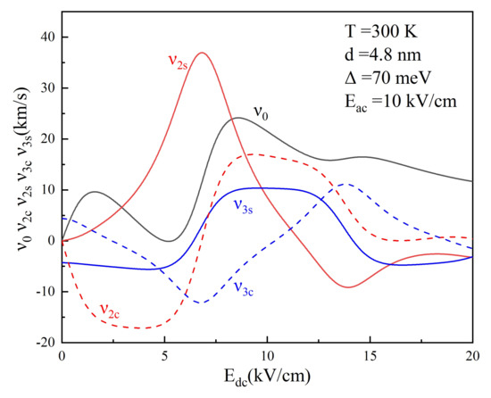
Figure 1.
DC component and harmonic coefficients , and of drifty velocity are plotted as a function of in GaAs-based superlattice driven by at . Other superlattice parameters are and .
By Electromagnetic Theory, the power of the emitted nth harmonic is defined as [27]
where m is the mesa area of a superlattice, and and c are the permeability and the speed of light, respectively. L is effective path length through the superlattice, and is the refractive index of GaAs. is the root-mean-square value of the nth component of the Fourier expansion of the induced current density written as
where is performed as an integration over the period .
Now, we consider the emitted power of the second and third harmonics at different lattice temperatures , , and for the same driving frequency . Figure 2a–c display the second harmonic power generated by the superlattice frequency multiplier as functions of and . Figure 2d–f reveals the third harmonic power as functions of and . The lattice temperatures are as follows: Figure 2a,d , Figure 2b,e , and Figure 2c,f . The red and orange areas indicate higher output power, while the blue zone represents a lower one. From Figure 2a–c, we can see that, at , , and , the power maxima of the second harmonic are , , and , respectively. With lattice temperature increasing to room temperature , the maximum power of the second harmonic is reduced, while the zone of output power is only slightly expanded. This tendency results from the decrease of electron drift velocity with the increase of the temperature. It is interesting that these maxima all appear at the same and regardless of the temperature. With the Bloch frequency , we further find that these peaks locate at exactly where and . The maximum power originates from resonance between driving terahertz AC frequency and intrinsic Bloch frequency. Figure 2d–f shows emitted power of the third harmonic at , , and , respectively. The corresponding maximum values of third harmonic power are , , and . Similar to the second harmonic, the maximum power decreases as the temperature increases. However, different from the second harmonic, in the power diagram of , locations of the main peaks are at and . The appearance at indicates that odd harmonic coefficients play a dominant role in the frequency tripler in the absence of a static electric field. Furthermore, by comparison of Figure 2a and Figure 2b, Figure 2b and Figure 2e, or Figure 2c and Figure 2f, we can conclude that the higher the harmonic order is, the weaker the output power exhibits. Thus, it is reasonable that we will not take the higher order harmonic radiation with into consideration in our study.
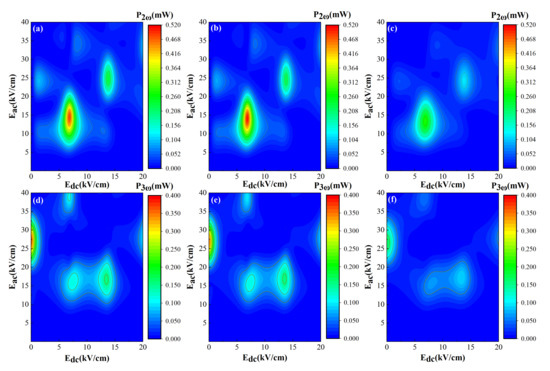
Figure 2.
The calculated second harmonic output powers (a–c) and third harmonic ones (d–f) as functions of and . The harmonic power is generated by a GaAs-based superlattice with driven by an AC electric field with frequency . The lattice temperatures are as follows: (a,d) , (b,e) , and (c,f) .
Since working at room temperature is an important feature of terahertz devices, we now focus on the harmonic generation of semiconductor superlattice at . Further insight on how driving frequency can affect the location of harmonic peak power is given by the color contour plot in Figure 3. Here, the driving frequencies are set as , , , and . Figure 3 shows that, by increasing the parameter , the emitted maximum power of and increase slowly. The power distribution of is shown in Figure 3a–d. The maximum of emitted power also occurs at the resonance between AC field and Bloch frequency . For example, Figure 3a displays that peaks of the second harmonic power appear at , , , and , etc. With the increase of DC bias or AC field , the magnitude of the peaks drops progressively. In particular, the distribution of the peaks shows a linear function dependence on and . Figure 3e–h depict the power distribution of , whose output power peak distribution is more complex and irregular than that of . The maximum power peak of appears at . As driving frequency increases, we observe that the power maximum of appears at a stronger AC electric field, ranging from to in Figure 3e–h. The other peak distributions of are not directly related to , which is different from that of the second harmonic. Figure 3e,f manifest that the magnitude of the secondary peak appearing at a small value of (, ) is half of the maximum peak. When driving frequency becomes large, as shown in Figure 3h for , the secondary peak splits into two with peak powers appearing at and , respectively.
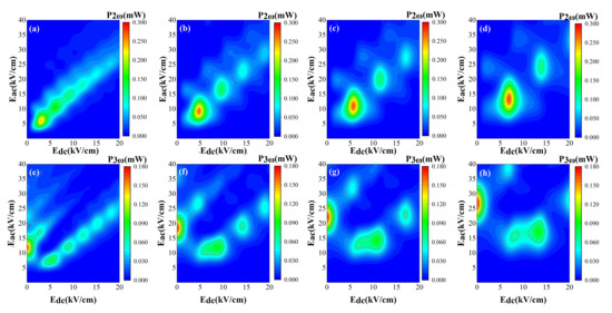
Figure 3.
The second and third harmonic output powers as functions of and . The period of superlattice is and temperature is . The AC electric field frequencies presented in figure are defined as follows: (a,e), (b,f) , (c,g) , and (d,h) .
To focus on the characteristic of versus static electric field, we show the emitted power profile of high order harmonic in Figure 4. Three different AC electric fields , , and are applied at room temperature with the same frequency . Despite the AC electric fields, the peak power appears at the same value of , where driving AC frequency is in resonance with Bloch frequency. The experimental demonstration of frequency doubling and tripling with semiconductor superlattice frequency multiplier has been reported in Ref. [25]. The superlattice consisting of 100 periods is grown by molecular beam epitaxy on a GaAs substrate. A corner cube antenna system can be fabricated to guide the terahertz radiation from a free-electron laser into the mesa element of frequency multiplier. The generated second and third harmonics are coupled out of the mesa by the corner cube antenna. The doping density of superlattice layers is . The experimental results of the second and third harmonic powers are reproduced in the insets of Figure 4. Our calculations of and are in qualitative consistence with the experiments [25]. It is noted that the experimental power is smaller by several orders and this may be attributed to light doping density and device loss in measurement of the experiment.
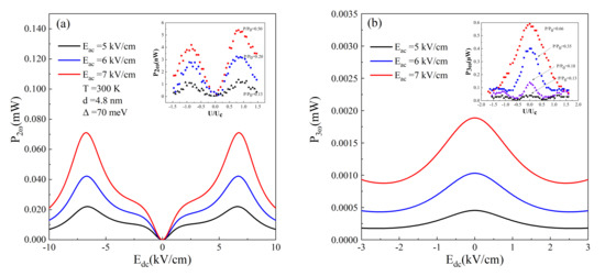
Figure 4.
(a) Second and (b) third harmonic output powers are plotted as functions of the DC electric field . The applied AC electric field is (black line), (red line), and (blue line), respectively. The lattice temperature is and the AC frequency is . The insets of (a,b) describe the experimental results of the second and third harmonic power, respectively, versus normalized voltage for different excitation power that is proportional to . Reprinted with permission from Ref. [25]. Copyright 2000 American Institute of Physics.
Finally, we demonstrate that the high order harmonic output power can be tuned by introducing a magnetic field perpendicular to the growth axis. Figure 5a,b exhibit and , respectively, as functions of . The applied AC electric field is set to be constant as while the magnetic fields are different as , , , , , and . The superlattice miniband width is and lattice temperature is still . The AC frequency is . Illustrated from Figure 5, the harmonic output power peak shifts to a stronger DC electric field with the magnetic field increasing. It can be understood by the fact that electrons perform cyclotron oscillation with frequency , which increases with magnetic field and corresponds to a stronger DC electric field. Interestingly, the harmonic power profile reveals that the magnetic field has no effect on the lineshape distribution, while magnitude of harmonic power is sensitive to the magnetic field. Thus, two-dimensional images rather than contour plots are used here. It is worth noting that, as shown in Figure 5b, output power enhances along with the increase of the magnetic field at not being universal, and this rule is broken at other values. On the whole, the magnetic field has an inhibitory effect on emitted harmonic power.
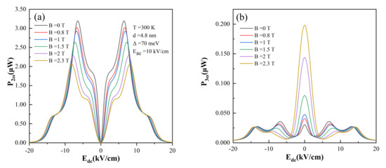
Figure 5.
(a) Second and (b) third harmonic output powers are plotted as functions of the DC electric field . The applied perpendicular magnetic fields are (black line), (red line), (blue line), (green line), (purple line), and (yellow line), respectively. The lattice temperature is and the AC frequency is .
4. Conclusions
In summary, using the balance equation approach with relaxation time depending on lattice temperature and miniband width, we theoretically analyze harmonic coefficients of drift velocity and emitted harmonic power of a semiconductor superlattice frequency multiplier in terahertz frequency range. It is found that high lattice temperature can suppress the peak of and result in enhancement of the peak width. Meanwhile, the peak of the second harmonic output power appears at the resonance between driving frequency and Bloch frequency. The peak distribution of is much more complicated except that the emission power maximum is dominant at . With the presence of the magnetic field, the peak position of emitted power can be tuned due to cyclotron oscillation. Our simulations are in good agreement with the experiments, which verifies the validity of the balance equation approach. The compact and efficient terahertz frequency multiplier based on a semiconductor superlattice is proposed to be a good candidate for terahertz wave generation.
Author Contributions
Methodology, C.W. and J.C.; Investigation, W.F., S.W., Y.Z. and C.W.; Formal analysis, W.F., S.W. and C.W.; Writing, W.F., S.W., Y.Z., C.W. and J.C.; Funding acquisition, W.F., C.W. and J.C. All authors have read and agreed to the submitted version of the manuscript.
Funding
The APC was funded by the Science and Technology Commission of Shanghai Municipal (Grant No. 21DZ1101102).
Institutional Review Board Statement
Not applicable.
Informed Consent Statement
Not applicable.
Data Availability Statement
The data that support the findings of this study are available from the corresponding author upon reasonable request.
Acknowledgments
This work was supported by the National Key R & D Program of China (Grant No. 2017YFA0701005), the National Natural Science Foundation of China (Grant Nos. 61927813, 61975225, 62005304, 62035014), and the Science and Technology Commission of Shanghai Municipal (Grant Nos. 21DZ1101102, 21ZR1474600).
Conflicts of Interest
The authors declare no conflict of interest.
References
- Esaki, L.; Tsu, R. Superlattice and negative differential conductivity in semiconductors. J. Res. Dev. 1970, 14, 61–65. [Google Scholar] [CrossRef]
- Lei, X.L. Current suppression and harmonic generation by intense terahertz fields in semiconductor superlattices. J. Appl. Phys. 1997, 82, 718–721. [Google Scholar] [CrossRef]
- Schomburg, E.; Ignatov, A.A.; Grenzer, J.; Renk, K.F.; Pavel’ev, D.G.; Koschurinov, Y.; Melzer, B.J.; Ivanov, S.; Schaposchnikov, S.; Kop’ev, P.S. Suppression of current through an Esaki–Tsu GaAs/AlAs superlattice by millimeter wave irradiation. Appl. Phys. Lett. 1996, 68, 1096–1098. [Google Scholar] [CrossRef]
- Hummel, A.B.; Blöser, C.; Bauer, T.; Roskos, H.G.; Kosevich, Y.A.; Kxoxhler, K. Electro-optic investigation of the Coherent Hall Effect in semiconductor superlattices. Phys. Status Solidi b 2005, 242, 1175–1178. [Google Scholar] [CrossRef]
- Soskin, S.M.; Khovanov, I.A.; McClintock, P.V.E. Regular rather than chaotic origin of the resonant transport in superlattices. Phys. Rev. Lett. 2015, 114, 166802. [Google Scholar] [CrossRef] [PubMed] [Green Version]
- Ying, L.; Huang, D.; Lai, Y.-C. Multistability, chaos, and random signal generation in semiconductor superlattices. Phys. Rev. E 2016, 93, 062204. [Google Scholar] [CrossRef] [Green Version]
- Shur, M. Recent developments in terahertz sensing technology. Proc. SPIE 2016, 9836, 98362Q. [Google Scholar] [CrossRef]
- Mekkalaki, A.; Kulkarni, M. Design of 16*16 high speed MLM using KOM for image filter application. In Proceedings of the 2016 International Conference on Electrical, Electronics, and Optimization Techniques (ICEEOT), Chennai, India, 3–5 March 2016; p. 3504. [Google Scholar]
- Sung, S.; Brown, E.R.; Grundfest, W.S.; Taylor, Z.D.; Selvin, S.; Bajwa, N.; Chantra, S.; Nowroozi, B.; Garritano, J.; Goell, J.; et al. THz Imaging System for in vivo Human Cornea. IEEE Trans. Terahertz Sci. Technol. 2018, 8, 27. [Google Scholar] [CrossRef]
- Qiu, F.C.; Tan, Z.Y.; Fu, Z.L.; Wan, W.J.; Li, M.Q.; Wang, C.; Cao, J.C. Reflective scanning imaging based on a fast terahertz photodetector. Opt. Commun. 2018, 427, 170–174. [Google Scholar] [CrossRef]
- Tessmann, A.; Schlechtweg, M.; Bruch, D.; Lewark, U.J.; Leuther, A.; Massler, H.; Wagner, S.; Seelmann-Eggebert, M.; Hurm, V.; Aidam, R.; et al. Terahertz monolithic integrated circuits based on metamorphic HEMT technology for sensors and communication. In Proceedings of the 2013 Asia-Pacific Microwave Conference Proceedings (APMC), Seoul, Korea, 5–8 November 2013. [Google Scholar]
- Wang, C.; Lu, B.; Miao, L.; Deng, X. 0.34 THz T/R front-end for wireless communication. High Power Laser Part. Beams 2013, 25, 1530–1534. [Google Scholar] [CrossRef]
- Zeng, H.; Liang, H.; Zhang, Y.; Wang, L.; Liang, S.; Gong, S.; Li, Z.; Yang, Z.; Zhang, X.; Lan, F.; et al. High-precision digital terahertz phase manipulation within a multichannel field perturbation coding chip. Nat. Photonics 2021, 15, 751–757. [Google Scholar] [CrossRef]
- Tonouchi, M. Cutting-edge terahertz technology. Nat. Photonics 2007, 1, 97–105. [Google Scholar] [CrossRef]
- Tunesi, J.; Peters, L.; Gongora, J.S.T.; Olivieri, L.; Fratalocchi, A.; Pasquazi, A.; Peccianti, M. Terahertz emission mediated by ultrafast time-varying metasurfaces. Phys. Rev. Res. 2021, 3, L042006. [Google Scholar] [CrossRef]
- Razavipour, S.G.; Dupont, E.; Fathololoumi, S.; Chan, C.W.I.; Lindskog, M.; Wasilewski, Z.R.; Aers, G.; Laframboise, S.R.; Wacker, A.; Hu, Q.; et al. An indirectly pumped terahertz quantum cascade laser with low injection coupling strength operating above 150 K. J. Appl. Phys. 2013, 113, 203107. [Google Scholar] [CrossRef]
- Agnew, G.; Grier, A.; Taimre, T.; Lim, Y.L.; Nikolić, M.; Valavanis, A.; Cooper, J.; Dean, P.; Khanna, S.P.; Lachab, M.; et al. Efficient prediction of terahertz quantum cascade laser dynamics from steady-state simulations. Appl. Phys. Lett. 2015, 16, 161105. [Google Scholar] [CrossRef] [Green Version]
- Wan, W.J.; Li, H.; Cao, J.C. Homogeneous spectral broadening of pulsed terahertz quantum cascade lasers by radio frequency modulation. Opt. Express 2018, 26, 980–989. [Google Scholar] [CrossRef]
- Qi, X.; Bertling, K.; Taimre, T.; Agnew, G.; Lim, Y.L.; Gillespie, T.; Robinson, A.; Brünig, M.; Demić, A.; Dean, P.; et al. Observation of optical feedback dynamics in single-mode terahertz quantum cascade lasers: Transient instabilities. Phys. Rev. A 2021, 103, 033504. [Google Scholar] [CrossRef]
- Khalatpour, A.; Paulsen, A.K.; Deimert, C.; Wasilewski, Z.R.; Hu, Q. High-power portable terahertz laser systems. Nat. Photonics 2021, 15, 16–20. [Google Scholar] [CrossRef]
- Grenzer, J.; Ignatov, A.A.; Schomburg, E.; Renk, K.F.; Pavel’ev, D.G.; Koschurinov, Y.; Melzer, B.; Ivanov, S.; Schaposchnikov, S.; Kop’ev, P.S. Microwave oscillator based on Bloch oscillations of electrons in a semiconductor superlattice. Ann. Phys. 1995, 507, 184–190. [Google Scholar] [CrossRef]
- Telenkov, M.P.; Mityagin, Y.A. Sequential resonant tunneling between landau levels in GaAs/AlGaAs superlattices in strong tilted magnetic and electric fields. Int. J. Mod. Phys. B 2007, 21, 1594–1599. [Google Scholar] [CrossRef]
- Gaifullin, M.B.; Alexeeva, N.V.; Hramov, A.E.; Makarov, V.V.; Maksimenko, V.A.; Koronovskii, A.A.; Greenaway, M.T.; Fromhold, T.M.; Patanè, A.; Mellor, C.J.; et al. Microwave generation in synchronized semiconductor superlattices. Phys. Rev. A 2017, 7, 044024. [Google Scholar] [CrossRef] [Green Version]
- Xia, J.B. Theory of terahertz-photocurrent resonances in miniband superlattices. Phys. Rev. B 1998, 58, 3565. [Google Scholar] [CrossRef] [Green Version]
- Winnerl, S.; Schomburg, E.; Brandl, S.; Kus, O.; Renk, K.F.; Wanke, M.C.; Allen, S.J.; Ignatov, A.A.; Ustinov, V.; Zhukov, A.; et al. Frequency doubling and tripling of terahertz radiation in a GaAs/AlAs superlattice due to frequency modulation of Bloch oscillations. Appl. Phys. Lett. 2000, 77, 1259–1261. [Google Scholar] [CrossRef]
- Pereira, M.F.; Zubelli, J.P.; Winge, D.; Wacker, A.; Rodrigues, A.S.; Anfertev, V.; Vaks, V. Theory and measurements of harmonic generation in semiconductor superlattices with applications in the 100 GHz to 1 THz range. Phys. Rev. B 2017, 96, 045306. [Google Scholar] [CrossRef] [Green Version]
- Apostolakis, A.; Pereira, M.F. Controlling the harmonic conversion efficiency in semiconductor superlattices by interface roughness design. AIP Adv. 2019, 9, 015022. [Google Scholar] [CrossRef] [Green Version]
- Pereira, M.F.; Anfertev, V.; Shevchenko, Y.; Vaks, V. Giant controllable gigahertz to terahertz nonlinearities in superlattices. Sci. Rep. 2020, 10, 15950. [Google Scholar] [CrossRef]
- Hyart, T.; Alekseev, K.N.; Leppänen, A.; Thuneberg, E.V. Terahertz Bloch oscillator with suppressed electric domains: Effect of elastic scattering. Int. J. Mod. Phys. B 2009, 23, 4459–4472. [Google Scholar] [CrossRef] [Green Version]
- Kroemer, H. Wave Packet Dynamics in a Biased Finite-Length Superlattice. arXiv 2003, arXiv:cond-mat/0310019. [Google Scholar]
- Ignatov, A.A.; Renk, K.F.; Dodin, E.P. Esaki-Tsu superlattice oscillator: Josephson-like dynamics of carriers. Phys. Rev. Lett. 1996, 70, 1996. [Google Scholar] [CrossRef]
- Lei, X.L.; Horing, N.J.M.; Cui, H.L. Microwave conductivity of a confined superlattice. Superlattices Microstruct. 1993, 14, 243. [Google Scholar] [CrossRef]
- Kosevich, Y.A. Anomalous Hall velocity, transient weak supercurrent, and coherent Meissner effect in semiconductor superlattices. Phys. Rev. B 2001, 63, 205313. [Google Scholar] [CrossRef]
- Cao, J.C.; Liu, H.C.; Lei, X.L. Chaotic dynamics in quantum-dot miniband superlattices. Phys. Rev. B 2000, 61, 5546. [Google Scholar] [CrossRef]
Publisher’s Note: MDPI stays neutral with regard to jurisdictional claims in published maps and institutional affiliations. |
© 2022 by the authors. Licensee MDPI, Basel, Switzerland. This article is an open access article distributed under the terms and conditions of the Creative Commons Attribution (CC BY) license (https://creativecommons.org/licenses/by/4.0/).