Abstract
Computational analysis using PSpice has become an indispensable tool for evaluating power electronics circuits, as it allows accurate simulation of transient effects, ripple, and component dynamics, enabling reliable assessment of complex topologies before physical implementation. In single-phase systems, electrolytic components are commonly used due to their high energy density, which helps mitigate low-frequency ripple caused by power oscillations between the DC and AC sides. However, these components have a limited lifespan, which compromises the system’s long-term reliability. This work proposes and evaluates the Stacked Switched Capacitor (SSC) topology as a power decoupling technique, implemented within a 200 W Cuk converter. The proposed SSC design enables a substantial reduction in required capacitance, replacing a conventional 600 μF capacitor with only three 36 μF capacitors, while maintaining voltage stability and output power performance. Simulation results show a high efficiency of 94% and a DC-link energy of 0.992 J, confirming the SSC’s ability to effectively mitigate voltage ripple at twice the grid angular frequency (2ω, rad/s) without compromising system durability. Comparative analysis with conventional decoupling strategies demonstrates that the SSC topology offers a compact, efficient, and reliable alternative, reducing the number of required passive components and switching devices. These results provide a strong basis for further exploration of SSC-based designs in space- and cost-constrained single-phase DC-AC applications.
1. Introduction
Electrolytic capacitors are essential in power conversion applications due to their high energy density. However, despite their widespread use, these devices face significant challenges that limit their reliability and lifespan. One of the most critical issues is the degradation of the electrolyte, which is the primary factor determining their performance [1]. Over time, the electrolyte evaporates, leading to an increase in Equivalent Series Resistance (ESR) and a decrease in capacitance, directly affecting the efficiency of the systems. ESR, in particular, generates heat in the capacitor, which can result in excessive heating and a reduced component lifespan, especially in high-power or high-frequency applications [2].
Despite advancements in materials and electrolytes, such as solid electrolytes and improved dielectrics, electrolytic capacitors still need to be aware of these issues. Operating temperature, thermal and electrical stress, and extreme usage conditions continue to be critical factors contributing to the degradation of these devices. For example, temperature directly impacts the lifespan of capacitors, with each 10 °C increase halving their durability [3]. Furthermore, overvoltage and manufacturing defects can accelerate aging and premature failure of capacitors.
In this context, stacked switched capacitors (SSC) emerge as an innovative solution to enhance power conversion systems’ reliability and energy density. This technique involves stacking multiple capacitors in a switched configuration, distributing the electrical and thermal stress across several elements, reducing the risk of premature failure, and extending the system’s lifespan [4]. Switching between capacitors also allows some capacitors to be deactivated while others operate, which improves overall reliability and minimizes the effects of localized degradation in a specific capacitor [5].
Although implementing the SSC architecture may increase system complexity and cost, its ability to enhance reliability and optimize energy density makes it a promising option for critical applications, such as power electronics and systems operating at high temperatures [6]. Through switching, the load can be balanced between capacitors, ensuring consistent and reliable performance, regardless of the technology or material used in the capacitors.
This article examines how the SSC architecture can overcome the inherent issues of traditional electrolytic capacitors while providing a more robust and efficient solution for energy applications. It demonstrates that, regardless of the capacitor material, the stacked switched architecture improves energy density and system reliability overall.
In the early stages of capacitor development, the materials available were limited, and liquid electrolytes were the standard choice for most electrolytic capacitors [7]. However, over time, advancements in materials science have enabled improvements in capacitor properties, addressing some of the most significant issues related to aging, reliability, and energy density [8].
- Electrode materials: Traditional electrolytic capacitors typically use aluminum or tantalum oxide as dielectric materials, which are prone to degradation over time due to gas bubble formation or electrolyte evaporation. In recent years, new dielectric materials such as multilayer ceramic films (BaTiO3, SrTiO3) and polymer-based dielectrics (polypropylene, polyethylene naphthalate) have been explored to enhance reliability and thermal performance [9,10]. These alternatives exhibit higher breakdown voltages and improved thermal stability than liquid-based electrolytes, thereby extending the operational lifespan of capacitors in high-temperature applications.
- Solid and polymer electrolytes: Solid-polymer capacitors, particularly those employing polythiophene (PEDOT) and polypyrrole (PPy) electrolytes, have attracted increasing attention. Unlike traditional liquid electrolytes, these solid-state materials eliminate evaporation and leakage issues, resulting in longer lifetime and lower equivalent series resistance (ESR) [11]. Furthermore, the enhanced ionic conductivity of polymer electrolytes enables higher efficiency in circuits with large ripple currents, making them suitable for compact and high-frequency power converters [12].
- New electrolytes: The development of hybrid and non-liquid electrolytes, including niobium oxide, tantalum oxide, and conductive polymer composites, has become a key area of research in advanced capacitor design [13]. These materials combine the stability of solid dielectrics with the high capacitance of electrolytic systems, significantly reducing degradation rates and improving performance under extreme thermal and electrical stress [14]. Consequently, they are increasingly used in high-reliability systems such as automotive, aerospace, and renewable energy converters.
In addition to material and architectural considerations, computational simulation plays a crucial role in evaluating power electronic circuits before physical implementation. In this work, the analysis and validation of the proposed Stacked Switched Capacitor (SSC) topology are performed entirely through OrCAD PSpice simulations, enabling the capture of transient phenomena, quantification of ripple effects, and evaluation of capacitor dynamics under varying load conditions. This simulation-driven approach establishes a solid foundation for design optimization. It aligns the study with widely adopted computational methodologies in modern power electronics research.
1.1. Impact of Material Advancements on Energy Density and Reliability
Energy density is one of the most valued properties in capacitors. Traditionally, electrolytic capacitors have been chosen for their high energy density compared to other technologies [15]. However, their long-term reliability has been challenging due to aging effects, heat, and electrolyte degradation.
- New technologies to improve energy density: with advancements in materials and architecture, SSC provide an innovative solution. By stacking multiple capacitors in a switched configuration, energy density is improved by allowing the system to utilize the total capacity of multiple capacitors while reducing individual stress on each one [16]. This results in improved reliability and thermal efficiency, leading to better space utilization and higher energy density for power systems.
- Capacitors with improved materials: advanced materials such as conductive polymers and ceramics have evolved capacitors to offer better performance, lower ESR [17], and higher energy storage capacity. This advancement in materials has enabled the design of capacitors that operate more efficiently at high frequencies and have excellent resistance to thermal degradation, enhancing the system’s overall reliability.
1.2. Stacked Switched Capacitor Architecture as a Solution to Overcome Limitations
- Despite material advancements, capacitor architecture remains critical to improving system reliability and energy density. SSC directly address the inherent reliability issues of traditional electrolytic capacitors.
- Distribution of electrical and thermal stress: the stacking technique evenly distributes electrical and thermal stress among the capacitors, reducing the risk of premature failure and improving system longevity [18]. This distribution enhances system efficiency regarding charge and discharge capacity, resulting in higher energy density.
- Flexibility and adaptability: SSC systems allow for dynamic switching between capacitors, providing greater flexibility in their operation. This is essential in applications with variable operating conditions, such as in renewable energy systems or high-frequency power electronics [19].
1.3. Simulation-Based Validation Approach
Simulation has become an essential step in evaluating advanced power decoupling techniques. In this work, OrCAD PSpice is employed as the primary environment to model and analyze stacked switched capacitor (SSC) topologies. This computational approach ensures that the proposed architectures are assessed under realistic operating conditions, allowing accurate validation of their behavior before physical implementation.
Ripple at twice the grid frequency is one of the leading causes of issues affecting systems designed for interconnection with the power grid. Table 1 provides a summary of these issues.

Table 1.
Effects on systems due to ripple at twice the grid frequency.
From the above, it is known that electrolytic capacitors unfortunately have temperature limitations and a reduced lifespan, making them undesirable for high-reliability applications. Consequently, the challenge of managing time-varying energy storage for single-phase conversion applications is well established.
In contrast to electrolytic capacitors, ceramic capacitors offer a longer lifespan [23]. However, directly substituting electrolytic capacitors with ceramic ones is not feasible due to the significant difference in energy density between the two technologies. Therefore, it is essential to consider approaches that reduce the amount of energy required to be stored in the DC link, aiming to employ components that, in principle, contribute to extending the overall system lifespan.
2. Decoupling Systems
Power decoupling methods are employed to minimize excess energy in the DC-link of grid-connected converters. These methods, which typically incorporate active switches and energy storage units, apply to AC–DC or DC–AC conversion systems [24].
These methods are broadlyclassified as independent (operating separately from the converter) or dependent (sharing converter switches) [25].
This classification is equivalent to the distinction between passive and active decoupling techniques, as shown in Figure 1.
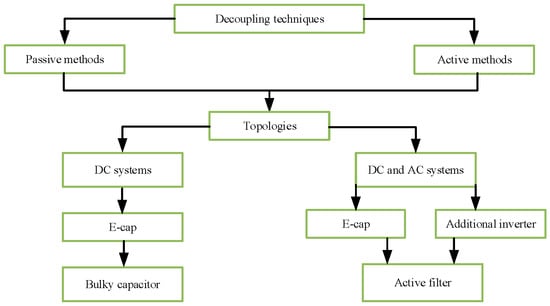
Figure 1.
Classification of decoupling techniques [19].
Passive methods, relying solely on capacitors, are bulky but straightforward due to the large capacitance required to smooth power oscillations. Their main drawbacks include high volume, weight, and limited lifetime. Conversely, active decoupling methods employ semiconductor switches and auxiliary circuits to reduce the required capacitance and improve system compactness [25,26].
2.1. Conventional Active Schemes
Conventional active approaches integrate auxiliary converters or energy buffers to regulate the DC-link voltage. Reported configurations have demonstrated reduced AC distortion, efficient use of film capacitors, and smaller capacitances [27,28,29,30,31,32,33]. However, these methods typically exhibit limitations such as high voltage stress or low efficiency in photovoltaic applications [34,35]
A summary of the main advantages and disadvantages of classical topologies is presented in Table 2.
Table 2.
Advantages and disadvantages of conventional schemes.
Among these methods, the SSC topology stands out as a more efficient solution. The SSC enables higher energy density and power capability by stacking multiple capacitors in a switched configuration [36,37]. Compared with conventional topologies, SSC architectures achieve higher efficiency, reduced ripple, and lower dependence on electrolytic components [38,39].
2.2. SSC Architecture
The SSC concept distributes electrical and thermal stress among stacked capacitors, improving reliability and energy density [37]. Two main variants are recognized: unipolar and bipolar architectures (Figure 2, Figure 3 and Figure 4) [40]. The unipolar scheme features a single energy path with a limited voltage range. In contrast, the bipolar configuration utilizes an H-bridge, enabling flexible series or parallel capacitor operation to balance voltages dynamically.
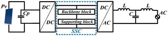
Figure 2.
Basic scheme by applying an SSC architecture [40].
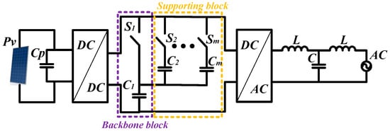
Figure 3.
Unipolar architecture [40].
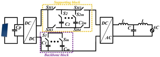
Figure 4.
Bipolar architecture [40].
Both configurations allow controlled charge/discharge among capacitors to maintain DC-link stability. The SSC topology minimizes switching and magnetic losses, thus enhancing efficiency and extending component lifespan density [38,39]. Its modular structure and scalability make it well-suited for renewable energy interfaces where space and lifetime constraints are critical.
2.3. Impact of Energy Regression on DC-Link Capacitor Sizing
The conventional analysis used to determine the size of the DC-link capacitor is generally based on the assumption that energy flows unidirectionally from the DC bus to the inverter. This assumption would be valid in the absence of passive filters, such as L or LCL filters, between the inverter and the grid; however, in real-world applications, these filters are essential to attenuate high-frequency harmonics generated by the inverter and to comply with grid code requirements. The inclusion of such filters introduces a phase shift between the voltage supplied by the inverter and the voltage at the grid side, a situation typically compensated for by the use of a Phase-Locked Loop (PLL), which aligns the inverter output to maintain a unity power factor at the grid connection point. However, this phase shift results in a non-unity power factor at the interface between the inverter and the passive filter, leading to a bidirectional flow of reactive power, with a portion of this energy being reflected back toward the inverter and consequently into the DC-link capacitor [41]. This phenomenon is referred to as energy regression and becomes more pronounced when the power factor at the grid connection point deviates from unity, a condition commonly associated with reactive power injection by the inverter. As a result, a greater amount of reactive energy is returned to the DC-link capacitor, increasing the voltage ripple and potentially compromising system stability. Although the PLL maintains synchronization with the grid, it does not prevent this energy regression toward the capacitor. The traditional solution has been to oversize the DC-link capacitor to ensure it can absorb the returned energy and keep the voltage ripple within acceptable limits. A recent study has presented and analyzed these phenomena in similar configurations in detail [42]; in this work, only the specific case of unity power factor operation at the point of common coupling with the grid is considered. Figure 5 illustrates the power flow through the capacitor between a DC-DC converter and a DC-AC inverter, highlighting the relationship between the input current (idc), the inverter current (iInv), and the capacitor current (iClink), which reflects the transient and oscillatory behavior associated with energy regression.
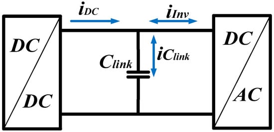
Figure 5.
Current flow through the DC-link capacitor [42].
2.4. Design Considerations for SSC Architectures
Various SSC topologies have been proposed, including unipolar and bipolar configurations; however, all energy buffering solutions based on SSCs presented so far employ capacitors without considering the effects of energy regression. This section analyzes capacitors in SSC architectures under new considerations, aiming to further enhance energy density compared to conventional designs. By adjusting the capacitance values and reconfiguring the arrangement of the capacitors, the goal is to maximize both operational efficiency and the system’s energy storage capacity. A key parameter in this analysis is the energy buffering ratio (Γb), defined as the ratio between the energy that can be injected and extracted during a charge/discharge cycle and the total energy capacity of the architecture [43].
Here, Rv is the voltage ripple ratio on the DC bus, and mmm is the number of support capacitors.
The higher the value of , the smaller the required energy buffer for a given amount of energy that needs to be absorbed. Therefore, maximizing the energy buffering ratio is a highly desirable objective.
By definition, the energy buffering ratio is given by [44]:
where Wmax and Wmin are the maximum and minimum values of the energy stored in the energy buffer under normal operating conditions, and Wrated is the total energy capacity. In the case of a unipolar SSC energy buffer with unequal capacitances, Wrated = Wmax; therefore, the expression simplifies to:
The maximum and minimum energy stored in an enhanced unipolar 1-m SSC energy buffer can be expressed in terms of the energy of the individual capacitors at the initial state (when fully charged, (4)) and at the final state (when fully discharged, (5)), respectively:
Here, and represent the initial and final voltages across the capacitor C1j at the beginning and end of the discharge period, respectively.
Figure 6 shows the voltage waveforms for an enhanced unipolar 1-m SSC energy buffer with different capacitance values, under discharge with a constant current during normal operation. These waveforms can be used to express the initial and final voltages across each capacitor in terms of the nominal DC bus voltage (Vnom).
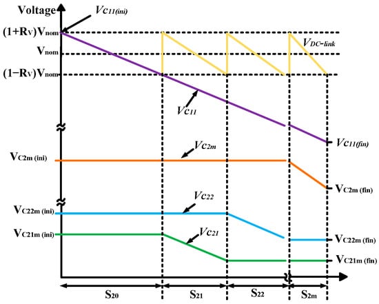
Figure 6.
Initial and final voltages.
When the configuration is fully charged (i.e., at the initial state), capacitor C11 is directly connected across the DC bus. Therefore, the initial voltage of C11 is equal to the maximum allowable voltage of the DC bus:
As the system discharges, the voltage across C11 decreases. When it reaches the minimum allowable value of , capacitor C21 is connected in series with C11 to raise the DC bus voltage.
In order for the DC bus voltage to reach its maximum allowable value again, the initial voltage of C21 must be:
Next, C11 and C21 discharge in series until the total voltage drop across them equals , and the DC bus reaches once again. Since both capacitors discharge with the same current, their individual voltage drops are inversely proportional to their capacitance values.
Therefore, the final voltage across C21 is given by:
To raise the DC bus voltage to its maximum allowable value, C22 is connected in series with C11. Subsequently, C11 and C22 discharge until the total voltage drop across them reaches . Then, C23 is connected in series with C11, and the discharge process continues. This sequence is repeated for all remaining support capacitors until C2m has also fully discharged [45].
Following the analysis of enhanced capacitor configurations with varying capacitance values to improve energy density in SSC systems, the next section presents a case study that illustrates the effective application of the proposed optimization techniques.
3. Case Study Design
This section presents the design of the case study, which involves implementing a Cuk converter. The selection of this converter topology is based on the requirement for a non-pulsating input current an essential characteristic in photovoltaic applications. Additionally, the Cuk converter enables effective reduction of current harmonics, which is necessary to meet power quality standards imposed by the electrical grid.
To ensure reliable and comparable results, specific performance metrics were established to assess each component’s behavior and design stage accurately. These metrics are essential for validating and quantitatively demonstrating why SSC constitute a substantial improvement over conventional architectures, particularly in terms of efficiency and the stability of the generated current.
3.1. Cuk Converter Design
The design parameters are presented in Table 3, and the design methodology is outlined in Table 4. It is worth noting that the input voltage (Vin) was selected based on the specifications of the photovoltaic module TSM-PDG5, which under standard irradiance conditions of 100 W/m2 at 25 °C specifies a maximum power point voltage (Vin) of 30.3 V.
Table 3.
Design parameters.
Table 4.
Results of the design methodology.
In the initial phase, essential criteria were established to ensure precision and consistency in system operation. Voltage and current ripples were standardized to specific target levels to guarantee design stability and reliability. Voltage ripple is constrained within a 5% margin, while current ripple is limited to a maximum of 10%. Table 4 summarizes the results obtained after applying the design methodology, providing the calculated component values for the proposed system.
In this study, the parameters of the simulated components were determined based on widely used commercial materials in medium-power converter applications. Aluminum electrolytic capacitors and ferrite-core inductors were chosen as reference components for the conventional case, reflecting their everyday use in DC-link designs [46]. In contrast, for the proposed SSC configuration, ceramic film capacitors were modeled due to their superior thermal stability, lower ESR, and extended operational lifetime [47]. Semiconductor devices were defined using silicon based MOSFET models available in the OrCAD PSpice component library. This material selection ensures a realistic and technically consistent comparison between conventional and SSC-based architectures, providing a sound basis for evaluating their performance under identical operating conditions.
3.2. Cuk Converter Simulation
All circuit configurations were modeled and evaluated in OrCAD PSpice (version 17.4) to ensure consistency in the comparative analysis. The simulations were performed using transient analysis with a time step of 1 µs and a total duration of 200 ms, which is sufficient to capture steady-state behavior under grid-frequency ripple conditions. Semiconductor switches were modeled with manufacturer-provided SPICE libraries, while passive components were defined according to the calculated values in Table 3, Table 4, Table 5, Table 6, Table 7 and Table 8. The photovoltaic source was represented by a constant DC input corresponding to the maximum power point voltage of 30.3 V at standard irradiance conditions.
Key performance metrics including DC bus voltage ripple, capacitor current stress, and energy storage behavior were extracted directly from the simulation outputs. This approach allows a precise comparison between conventional electrolytic capacitors, standard SSC configurations, and the enhanced SSC architecture. By standardizing the simulation environment, the results provide reproducible and quantitative evidence of the advantages of SSC systems for power decoupling in single-phase DC–AC applications.
4. Simulation Results
This section presents the simulation results obtained using OrCAD-PSpice for the Cuk converter, the increase in capacitance with an AC port, and the implementation of the unipolar SSC architecture (Section 4.2).
These results are critical for evaluating the practical performance of the proposed design and for validating its effectiveness under simulated operating conditions.
4.1. Simulation Results of the Cuk Converter
Figure 7 shows the schematic diagram of the Cuk converter circuit. This detailed representation provides a visual overview of the circuit configuration, including the layout of key components such as inductors, capacitors, and switching elements.
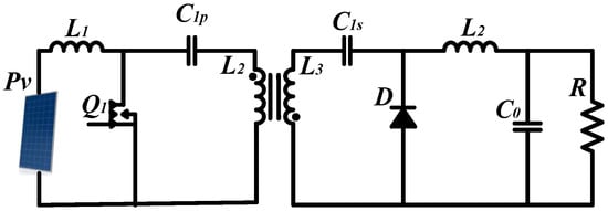
Figure 7.
Cuk converter.
The circuit visualization provides a clear understanding of the Cuk converter’s topology and operational principles
To validate the converter’s operation, it is necessary to obtain the output values through simulation. Figure 8 illustrates an output voltage of 207 V from the converter. This result is notably close to the intended design voltage of 210 V. In terms of power, the simulation yields an output of 195 W, whereas the required power to meet the system specifications is 200 W. This level of approximation demonstrates the converter’s practical ability to meet the system’s power demand.
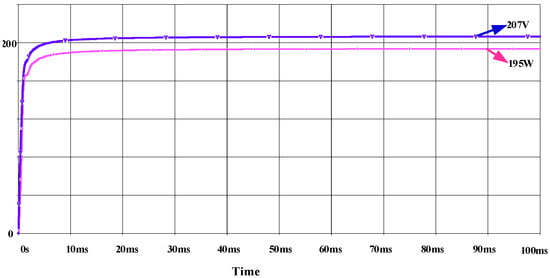
Figure 8.
Cuk converter result.
4.2. Results of the Cuk Converter with AC Port
The schematic of the Cuk converter combined with the AC inverter (H-bridge) is presented. Figure 9 provides a complete representation of the connection between the converter and the inverter.
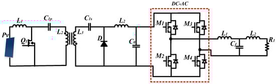
Figure 9.
Cuk converter AC-port.
When the AC port is connected to the converter, the significant increase in DC-link capacitance from 0.12 μF to 601.5 μF is attributed to the system’s inherent nature and its operational demands. The DC-link capacitor plays a critical role in energy conversion and in interfacing the converter with the AC source. Its sizing is essential for fulfilling multiple functions, including voltage ripple mitigation and DC supply stabilization. Upon integration with the AC port, the Cuk converter operates in conjunction with the inverter to accommodate AC fluctuations and ensure a controlled and stable power delivery.
The increased capacitance is directly related to the need for efficient energy buffering, especially considering that AC power varies at twice the grid frequency, as illustrated in Figure 10. This higher capacitance enables the system to effectively manage input fluctuations, smooth the output voltage, and ensure a continuous and reliable energy supply.
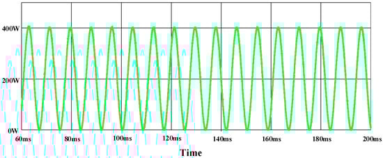
Figure 10.
AC power fluctuations.
4.3. Results of the Cuk Converter with the SSC Architecture
Table 5 and Table 6 summarize the main design parameters and calculated results for the stacked switched capacitor (SSC) architecture in its unipolar configuration. The design process follows the analytical procedure described in [44], which determines the required capacitance to achieve the desired voltage ripple and energy balance on the DC bus.
This unipolar configuration demonstrates a substantial reduction in the required capacitance, as the system now employs four 15 μF capacitors instead of a single 600 μF capacitor while maintaining equivalent decoupling performance.
Table 5.
Key design parameters of the SSC system.
Table 5.
Key design parameters of the SSC system.
| Parameter | Symbol | Value |
|---|---|---|
| Power | 200 W | |
| Backbone capacitors | n | 1 |
| Support capacitors | m | 3 |
| Maximum voltage | 270 V | |
| Minimum voltage | 140 V | |
| Nominal voltage | 210 V | |
| Percentage of ripple on DC bus | 10% | |
| Angular frequency | 377 rad/s |
Table 6 presents the calculated capacitance for the SSC system, derived from the design parameters listed in Table 5 and following the methodology described in [44]. This approach ensures that the SSC configuration meets the targeted voltage ripple and energy distribution requirements for the system.
Table 6.
Calculated capacitance of the SSC system [44].
Table 6.
Calculated capacitance of the SSC system [44].
| Equation | Result |
|---|---|
| 1.6 | |
| 15 μF |
Figure 11 provides a representation of the system with the AC port, incorporating the unipolar SSC architecture.
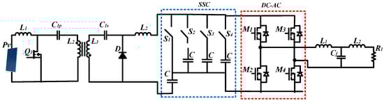
Figure 11.
Cuk converter unipolar architecture.
To visualize the results using the unipolar SSC architecture as the DC link, Figure 12 shows the AC power, which varies at twice the grid frequency and reaches a peak of 387 W. Meanwhile, Figure 13 illustrates the voltage stability on the DC side, with a ripple of only 5 V, confirming the SSC architecture’s ability to maintain the desired operating levels.
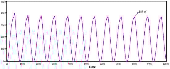
Figure 12.
AC power fluctuations.
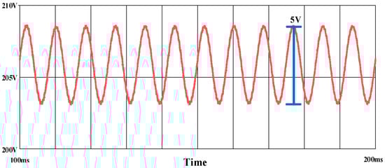
Figure 13.
DC link voltage.
In DC-AC applications, efficiency and power decoupling performance are critical factors for ensuring optimal system operation. Given the wide variety of active systems available on the market, it is essential to conduct detailed comparisons among different system types to make informed decisions and enhance application design. The need to compare results across various active systems lies in the pursuit of improvements in efficiency, stability, and the dynamic response of DC-AC converters.
4.4. Results of the Cuk Converter with the Enhanced SSC Architecture
Table 7 and Table 8 summarize the design parameters and calculated capacitance values for the SSC system under new considerations related to energy regression. This configuration aims to enhance output power while maintaining voltage ripple constraints. The unipolar 1–2 configuration achieved capacitance values of 36 µF, resulting in improved system performance and reduced energy imbalance across the capacitive stages.
Table 7.
Key design parameters of the SSC system under energy regression conditions [44].
Table 7.
Key design parameters of the SSC system under energy regression conditions [44].
| Parameter | Symbol | Value |
|---|---|---|
| Power | 200 W | |
| Backbone capacitors | n | 1 |
| Support capacitors | m | 2 |
| Maximum voltage | 270 V | |
| Minimum voltage | 140 V | |
| Nominal voltage | 210 V | |
| Percentage of ripple on DC bus | 10% | |
| Angular frequency | 377 rad/s |
Table 8.
Calculated capacitance of the SSC system under the 1–2 configuration [42].
Table 8.
Calculated capacitance of the SSC system under the 1–2 configuration [42].
| Equation | Result |
|---|---|
| 36.28 μF |
To visualize the system behavior, Figure 14 displays the AC power profile, which fluctuates at twice the grid frequency and reaches a peak of 390 W. Understanding the behavior of energy stored in the capacitances is essential especially when comparing different types of capacitors in applications such as the 200 W case, where the goal is to improve performance and reduce the size of the DC-link component.
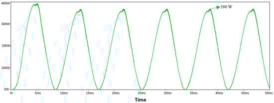
Figure 14.
AC power fluctuations.
Table 9 presents a comparative analysis of energy performance across different DC-link architectures, including the electrolytic capacitor, the standard SSC system, and the improved SSC configuration.
Table 9.
Energy distribution in the various DC-Link components [48].
In this context, it is necessary to analyze how an electrolytic capacitor behaves in terms of energy storage and release, taking into account factors such as energy regression, which can negatively affect its performance. This analysis is crucial for identifying the limitations and advantages of using electrolytic capacitors in high-demand energy applications.
When this behavior is compared to that of capacitors in a standard SSC system, the improvement in energy management becomes evident, with reduced losses and enhanced performance. Furthermore, in an improved SSC system featuring enhanced switching and energy distribution capabilities a significant gain in both efficiency and responsiveness to power fluctuations is demonstrated. This improved performance surpasses the limitations of traditional electrolytic capacitors, providing a more stable and reliable operation over time.
When analyzing the energy distribution results presented in Table 10, it becomes clear that the improved SSC topology offers significant advantages in terms of efficiency, reduced passive component volume, and enhanced energy management. To further contextualize these improvements, Table 10 presents a comparative analysis of the proposed SSC system and other reference topologies from the literature, highlighting their key features, performance metrics, and trade-offs in single-phase grid-connected applications.
Table 10.
Comparison of topologies for reducing the passive power-decoupling component in single-phase grid-connected applications.
5. Comparison of Conventional and Proposed SSC Topologies
Table 10 summarizes the key features of the proposed stacked switched capacitor (SSC) topology and several conventional active decoupling models reported in [33,34,35], which are used here as reference benchmarks. These reference topologies include typical active decoupling circuits and classical SSC-based configurations commonly applied in microinverter and grid-connected systems. The comparison focuses on crucial aspects such as capacitor size, efficiency, energy storage capability, and switching complexity, to highlight the advantages and trade-offs of the proposed SSC approach.
- Advantages of the proposed SSC topology:
The SSC design significantly reduces capacitor size compared to conventional solutions, using only three 15 μF for power decoupling, which is particularly beneficial for space-constrained applications. It achieves high efficiency (94%), comparable to other advanced microinverter designs. The topology employs fewer switching devices (10), simplifying the control strategy compared to more complex configurations, such as the microinverter in Ref. [34], which uses 16 switching devices.
- Disadvantages:
The SSC exhibits lower DC-link energy (0.992 J) than some reference models (e.g., Ref. [35] with 3.125 J), potentially limiting transient energy buffering.
Output filtering options are more constrained by the SSC architecture, potentially limiting flexibility in specific applications.
- Trade-offs and rationale:
The SSC topology prioritizes compactness and reduced component count over maximum energy storage.
Reference models with higher DC-link energy and larger passive elements (Refs. [33,34,35]) provide superior transient buffering but at the cost of increased size, complexity, and number of switching devices.
- Application-based decision-making:
For space- or cost-sensitive microinverters, the SSC topology is advantageous due to its compact design and minimal components.
For applications that require ample transient energy storage or very high DC-link energy, the reference topologies may be more appropriate despite their higher complexity.
This discussion provides a comprehensive comparison of the strengths, weaknesses, and trade-offs of each approach, offering guidance on selecting the most suitable topology for specific application requirements.
6. Concluding Remarks
Following a detailed analysis of the results presented in Table 10, several key conclusions can be drawn:
The SSC topology enables a substantial reduction in required capacitance, replacing a single 600 μF capacitor with just four 15 μF capacitors, thereby improving energy efficiency, optimizing physical space, and lowering passive component costs.
The architecture does not require high-end components and operates at a relatively low switching frequency, further reducing implementation costs and making it a practical solution for DC-AC applications.
A careful balance between system performance and structural complexity is highlighted, as the SSC topology achieves high efficiency with a moderate number of switching devices, in contrast to some conventional designs that require many components.
The SSC reduces reliance on electrolytic capacitors, offering a compact, durable, and sustainable alternative without compromising overall efficiency.
Energy storage and delivery within the DC-link confirm the robustness of the SSC architecture, demonstrating performance comparable to or better than recent proposals.
All results were validated through circuit-level simulations in OrCAD PSpice, providing a reproducible framework for comparing conventional and SSC-enhanced architectures and offering a reliable basis for future experimental validation.
Future Work
Future stages of this research will focus on the experimental validation of the proposed SSC topology through the development of a physical prototype. This implementation will allow the evaluation of energy efficiency, thermal behavior, and component reliability under real operating conditions, providing further insight into the practical feasibility of the SSC-based active decoupling approach.
Author Contributions
Conceptualization, O.R.-B., M.P.-S. and R.E.L.-P.; methodology, O.R.-B., C.C.-G., A.G.-O. and M.P.-S.; investigation, O.R.-B., M.P.-S., R.E.L.-P. and M.D.C.T.-P.; resources, O.R.-B., M.P.-S., R.E.L.-P., M.D.C.T.-P. and J.A.G.-F.; writing—original draft preparation, O.R.-B.; writing—review and editing, O.R.-B., M.P.-S., C.C.-G., A.G.-O. and R.E.L.-P.; visualization, O.R.-B., M.D.C.T.-P. and J.A.G.-F.; supervision O.R.-B., C.C.-G., A.G.-O. and M.P.-S. All authors have read and agreed to the published version of the manuscript.
Funding
This research received no external funding.
Data Availability Statement
The original contributions presented in this study are included in the article. Further inquiries can be directed to the corresponding author.
Conflicts of Interest
The authors declare no conflicts of interest.
Abbreviations
The following abbreviations are used in this manuscript:
| AC | Alternate Current |
| DC | Direct Current |
| ESR | Equivalent Series Resistance |
| SSC | Stacked Switched Capacitors |
| MPPT | Maximum Power Point Tracking |
| VPMP | Maximum Power Point Voltage |
| PV | Photovoltaic Solar |
| PLL | Phase-Locked Loop |
References
- Liu, W.; Sun, X.; Yan, X.; Gao, Y.; Zhang, X.; Wang, K.; Ma, Y. Review of Energy Storage Capacitor Technology. Batteries 2024, 10, 271. [Google Scholar] [CrossRef]
- Wang, H.; Davari, P.; Wang, H.; Kumar, D.; Zare, F.; Blaabjerg, F. Lifetime Estimation of DC-Link Capacitors in Adjustable Speed Drives Under Grid Voltage Unbalances. IEEE Trans. Power Electron. 2019, 34, 4064–4078. [Google Scholar] [CrossRef]
- Roman, D.; Saxena, S.; Bruns, J.; Valentin, R.; Pecht, M.; Flynn, D. A Machine Learning Degradation Model for Electrochemical Capacitors Operated at High Temperature. IEEE Access 2021, 9, 25544–25553. [Google Scholar] [CrossRef]
- Barzegarkhoo, R.; Forouzesh, M.; Lee, S.S.; Blaabjerg, F.; Siwakoti, Y.P. Switched-Capacitor Multilevel Inverters: A Comprehensive Review. IEEE Trans. Power Electron. 2022, 37, 11209–11243. [Google Scholar] [CrossRef]
- Zhao, Z.; Davari, P.; Lu, W.; Wang, H.; Blaabjerg, F. An Overview of Condition Monitoring Techniques for Capacitors in DC-Link Applications. IEEE Trans. Power Electron. 2021, 36, 3692–3716. [Google Scholar] [CrossRef]
- Chowdhury, S.; Gurpinar, E.; Ozpineci, B. Capacitor Technologies: Characterization, Selection, and Packaging for Next-Generation Power Electronics Applications. IEEE Trans. Transp. Electrif. 2022, 8, 2710–2720. [Google Scholar] [CrossRef]
- Torki, J.; Joubert, C.; Sari, A. Electrolytic capacitor: Properties and operation. J. Energy Storage 2023, 58, 106330. [Google Scholar] [CrossRef]
- Zhang, C.; Zheng, Y.; Jing, J.; Liu, Y.; Huang, H. A comparative LCA study on aluminum electrolytic capacitors: From liquid-state electrolyte, solid-state polymer to their hybrid. J. Clean. Prod. 2022, 375, 134044. [Google Scholar] [CrossRef]
- Wu, H.; Zhuo, F.; Qiao, H.; Kodumudi Venkataraman, L.; Zheng, M.; Wang, S.; Huang, H.; Li, B.; Mao, X.; Zhang, Q. Polymer-/Ceramic-based Dielectric Composites for Energy Storage and Conversion. Energy Environ. Mater. 2022, 5, 486–514. [Google Scholar] [CrossRef]
- Zhou, L.; Zhao, S.; Xie, P.; Miao, X.; Liu, S.; Sun, N.; Guo, M.; Xu, Z.; Zhong, T.; Shen, Y. Research progress and prospect of polymer dielectrics. Appl. Phys. Rev. 2023, 10, 031310. [Google Scholar] [CrossRef]
- Zhang, T.; Wu, J.; Ran, F. Poly(3, 4-Ethylenedioxythiophene) as Promising Energy Storage Materials in Zinc-Ion Batteries. Macromol. Rapid Commun. 2024, 45, 2400476. [Google Scholar] [CrossRef]
- Kang, J.; Yan, Z.; Gao, L.; Zhang, Y.; Liu, W.; Yang, Q.; Zhao, Y.; Deng, N.; Cheng, B.; Kang, W. Improved ionic conductivity and enhancedinterfacial stability of solid polymer electrolytes with porous ferroelectric ceramic nanofibers. Energy Storage Mater. 2022, 53, 192–203. [Google Scholar] [CrossRef]
- Liu, L.; Qu, J.; Gu, A.; Wang, B. Percolative polymer composites for dielectric capacitors: A brief history, materials, and multilayer interface design. J. Mater. Chem. A 2020, 8, 18515–18537. [Google Scholar] [CrossRef]
- Chen, S.-Y.; Hsieh, C.-T.; Zhang, R.-S.; Mohanty, D.; Gandomi, Y.A.; Hung, I.M. Hybrid solid state electrolytes blending NASICON-type Li1+xAlxTi2−x(PO4)3 with poly(vinylidene fluoride-co-hexafluoropropene) for lithium metal batteries. Electrochim. Acta 2022, 427, 140903. [Google Scholar] [CrossRef]
- Burke, A. Prospects for the Development of High Energy Density Dielectric Capacitors. Appl. Sci. 2021, 11, 8063. [Google Scholar] [CrossRef]
- Ye, Z.; Lei, Y.; Pilawa-Podgurski, R.C.N. The Cascaded Resonant Converter: A Hybrid Switched-Capacitor Topology with High Power Density and Efficiency. IEEE Trans. Power Electron. 2020, 35, 4946–4958. [Google Scholar] [CrossRef]
- He, G.; Li, X.; Luo, H.; Zhang, D.; Zhang, S. The Large-Scale Manufacturing of Polymer Dielectric Capacitors: Advancements and Challenges. Adv. Mater. 2025, 37, e2419563. [Google Scholar] [CrossRef]
- Kumari, M.; Siddique, M.D.; Sarwar, A.; Tariq, M.; Mekhilef, S.; Iqbal, A. Recent trends and review on switched-capacitor-based single-stage boost multilevel inverter. Int. Trans. Electr. Energy Syst. 2021, 31, e12730. [Google Scholar] [CrossRef]
- Rodríguez-Benítez, O.; Ponce-Silva, M.; Aqui-Tapia, J.A.; Rodríguez-Benítez, Ó.M.; Lozoya-Ponce, R.E.; Adamas-Pérez, H. Active Power-Decoupling Methods for Photovoltaic-Connected Applications: An Overview. Processes 2023, 11, 1808. [Google Scholar] [CrossRef]
- Aguila-Leon, J.; Vargas-Salgado, C.; Chiñas-Palacios, C.; Díaz-Bello, D. Solar photovoltaic Maximum Power Point Tracking controller optimization using Grey Wolf Optimizer: A performance comparison between bio-inspired and traditional algorithms. Expert Syst. Appl. 2023, 211, 118700. [Google Scholar] [CrossRef]
- Guo, R.; Han, W. The effects of electrolytes, electrolyte/electrode interphase, and binders on lithium-ion batteries at low temperature. Mater. Today Sustain. 2022, 19, 100187. [Google Scholar] [CrossRef]
- Laycox, C.A.; Thompson, R.; Haggerty, J.A.; Wilkins, A.J.; Haigh, S.M. Flicker and reading speed: Effects on individuals with visual sensitivity. Perception 2024, 53, 512–528. [Google Scholar] [CrossRef]
- Chuong, K.Y.; Bock, J.A.; Patterson, E.A.; Brown-Shaklee, H.J.; Graber, L.; Garten, L.M. Increasing Multilayer Ceramic Capacitor Lifetime With Bipolar Voltage Cycling. IEEE Trans. Compon. Packag. Manuf. Technol. 2025, 15, 272–280. [Google Scholar] [CrossRef]
- Gong, Z.; Liu, C.; Gui, Y.; Silva, F.F.d.; Bak, C.L. Power Decoupling Method for Voltage Source Inverters Using Grid Voltage Modulated Direct Power Control in Unbalanced System. IEEE Trans. Power Electron. 2023, 38, 3084–3099. [Google Scholar] [CrossRef]
- Liu, Y.; Zhang, W.; Sun, Y.; Su, M.; Xu, G.; Dan, H. Review and comparison of control strategies in active power decoupling. IEEE Trans. Power Electron. 2021, 36, 14436–14455. [Google Scholar] [CrossRef]
- Li, H.; Zhang, K.; Zhao, H.; Fan, S.; Xiong, J. Active Power Decoupling for High-Power Single-Phase PWM Rectifiers. IEEE Trans. Power Electron. 2013, 28, 1308–1319. [Google Scholar] [CrossRef]
- Pan, X.; Li, H.; Liu, Y.; Zhao, T.; Ju, C.; Rathore, A.K. An Overview and Comprehensive Comparative Evaluation of Current-Fed-Isolated-Bidirectional DC/DC Converter. IEEE Trans. Power Electron. 2020, 35, 2737–2763. [Google Scholar] [CrossRef]
- Tang, Y.; Blaabjerg, F. Power decoupling techniques for single-phase power electronics systems—An overview. In Proceedings of the 2015 IEEE Energy Conversion Congress and Exposition (ECCE), Montreal, QC, Canada, 20–24 September 2015. [Google Scholar]
- Isik, S.; Alharbi, M.; Bhattacharya, S. An Optimized Circulating Current Control Method Based on PR and PI Controller for MMC Applications. IEEE Trans. Ind. Appl. 2021, 57, 5074–5085. [Google Scholar] [CrossRef]
- Sun, Y.; Liu, Y.; Su, M.; Xiong, W.; Yang, J. Review of Active Power Decoupling Topologies in Single-Phase Systems. IEEE Trans. Power Electron. 2016, 31, 4778–4794. [Google Scholar] [CrossRef]
- Fan, S.; Xue, Y.; Zhang, K. A novel active power decoupling method for single-phase photovoltaic or energy storage applications. In Proceedings of the 2012 IEEE Energy Conversion Congress and Exposition (ECCE), Raleigh, NC, USA, 15–20 September 2012; IEEE: New York, NY, USA, 2012. [Google Scholar]
- Yang, Z.; Zeng, J.; Zhang, Q.; Zhang, Z.; Winstead, V.; Yu, D. A Composite Power Decoupling Method for a PV Inverter with Optimized Energy Buffer. IEEE Trans. Ind. Appl. 2021, 57, 3877–3887. [Google Scholar] [CrossRef]
- Liu, Y.; Sun, Y.; Su, M.; Li, X.; Ning, S. A Single Phase AC/DC/AC Converter with Unified Ripple Power Decoupling. IEEE Trans. Power Electron. 2018, 33, 3204–3217. [Google Scholar] [CrossRef]
- Zhang, J.; Ding, H.; Wang, B.; Guo, X.; Padmanaban, S. Active power decoupling for current source converters: An overview scenario. Electronics 2019, 8, 197. [Google Scholar] [CrossRef]
- Vitorino, M.A.; Alves, L.F.S.; Wang, R.; Corrêa, M.B.d.R. Low-Frequency Power Decoupling in Single-Phase Applications: A Comprehensive Overview. IEEE Trans. Power Electron. 2017, 32, 2892–2912. [Google Scholar] [CrossRef]
- Liao, Z.; Brooks, N.C.; Pilawa-Podgurski, R.C.N. Design Constraints for Series-Stacked Energy Decoupling Buffers in Single-Phase Converters. IEEE Trans. Power Electron. 2018, 33, 7305–7308. [Google Scholar] [CrossRef]
- Tang, Y.; Chen, M.; Ran, L. Design and control of a compact MMC submodule structure with reduced capacitor size using the stacked switched capacitor architecture. In Proceedings of the 2016 IEEE Applied Power Electronics Conference and Exposition (APEC), Long Beach, CA, USA, 20–24 March 2016. [Google Scholar]
- de Souza, A.F.; Tofoli, F.L.; Ribeiro, E.R. Switched Capacitor DC-DC Converters: A Survey on the Main Topologies, Design Characteristics, and Applications. Energies 2021, 14, 2231. [Google Scholar] [CrossRef]
- Barth, C.B.; Foulkes, T.; Moon, I.; Lei, Y.; Qin, S.; Pilawa-Podgurski, R.C.N. Experimental Evaluation of Capacitors for Power Buffering in Single-Phase Power Converters. IEEE Trans. Power Electron. 2019, 34, 7887–7899. [Google Scholar] [CrossRef]
- Ni, Y.; Pervaiz, S.; Chen, M.; Afridi, K.K. Energy Density Enhancement of Stacked Switched Capacitor Energy Buffers Through Capacitance Ratio Optimization. IEEE Trans. Power Electron. 2017, 32, 6363–6380. [Google Scholar] [CrossRef]
- Upadhyay, N.; Padhy, N.P.; Agarwal, P. Grid-Current Control with Inverter-Current Feedback Active Damping for LCL Grid-Connected Inverter. IEEE Trans. Ind. Appl. 2024, 60, 1738–1749. [Google Scholar] [CrossRef]
- Adamas-Pérez, H.; Ponce-Silva, M.; Mina-Antonio, J.D.; Claudio-Sánchez, A.; Rodríguez-Benítez, O.; Rodríguez-Benítez, O.M. A New LCL Filter Design Method for Single-Phase Photovoltaic Systems Connected to the Grid via Micro-Inverters. Technologies 2024, 12, 89. [Google Scholar] [CrossRef]
- Chen, M.; Afridi, K.K.; Perreault, D.J. Stacked Switched Capacitor Energy Buffer Architecture. IEEE Trans. Power Electron. 2013, 28, 5183–5195. [Google Scholar] [CrossRef]
- Pervaiz, S.; Kumar, A.; Afridi, K.K. A Compact Electrolytic-Free Two-Stage Universal Input Offline LED Driver with Volume-Optimized SSC Energy Buffer. IEEE J. Emerg. Sel. Top. Power Electron. 2018, 6, 1116–1130. [Google Scholar] [CrossRef]
- Paul, R.; Hassan, A.; Mantooth, H.A. A Double-Sided Cooled Power Module with Embedded Decoupling Capacitors. IEEE J. Emerg. Sel. Top. Power Electron. 2024, 12, 1813–1821. [Google Scholar] [CrossRef]
- Ebrahimi, J.; Akbari, A.; Eren, S.; Bakhshai, A. A Single-Phase Seven-Level Nested Switched-Capacitor Converter with Enhancing Lifetime and Reducing Size of Flying Capacitors. IEEE Trans. Power Electron. 2025, 40, 9234–9248. [Google Scholar] [CrossRef]
- Lv, C.; Liu, J.; Zhang, Y.; Lei, W.; Cao, R. An improved lifetime prediction method for metallized film capacitor considering harmonics and degradation process. Microelectron. Reliab. 2020, 114, 113892. [Google Scholar] [CrossRef]
- Chen, M.; Ni, Y.; Serrano, C.; Montgomery, B.; Perreault, D.; Afridi, K. An electrolytic-free offline LED driver with a ceramic-capacitor-based compact SSC energy buffer. In Proceedings of the 2014 IEEE Energy Conversion Congress and Exposition (ECCE), Pittsburgh, PA, USA, 14–18 September 2014. [Google Scholar]
- Alhuwaishel, F.M.; Enjeti, P. An Electrolytic capacitor less non-isolated Microinverter with Integrated Battery Storage System for Residential Applications. In Proceedings of the 2024 IEEE Applied Power Electronics Conference and Exposition (APEC), Long Beach, CA, USA, 25–29 February 2024. [Google Scholar]
- Shen, Y.; Zakzewski, D.; Hasnain, A.; Resalayyan, R.; Khaligh, A. Sensorless Control for DC-Parallel Active Power Decoupling in PV Microinverters. IEEE Trans. Power Electron. 2023, 38, 14628–14637. [Google Scholar] [CrossRef]
- Alsolami, M. Active Power Decoupling for Single-Phase Grid-Connected PV System using a Ripple Port. Arab. J. Sci. Eng. 2021, 46, 9981–9993. [Google Scholar] [CrossRef]
- Pereira, T.A.; Martins, D.C.; Coelho, R.F. Active-capacitor for power decoupling in single-phase grid-connected converters. In Proceedings of the 2019 IEEE 15th Brazilian Power Electronics Conference and 5th IEEE Southern Power Electronics Conference (COBEP/SPEC), Santos, Brazil, 1–4 December 2019; IEEE: New York, NY, USA, 2019. [Google Scholar]


Disclaimer/Publisher’s Note: The statements, opinions and data contained in all publications are solely those of the individual author(s) and contributor(s) and not of MDPI and/or the editor(s). MDPI and/or the editor(s) disclaim responsibility for any injury to people or property resulting from any ideas, methods, instructions or products referred to in the content. |
© 2025 by the authors. Licensee MDPI, Basel, Switzerland. This article is an open access article distributed under the terms and conditions of the Creative Commons Attribution (CC BY) license (https://creativecommons.org/licenses/by/4.0/).